Table of Contents
Advertisement
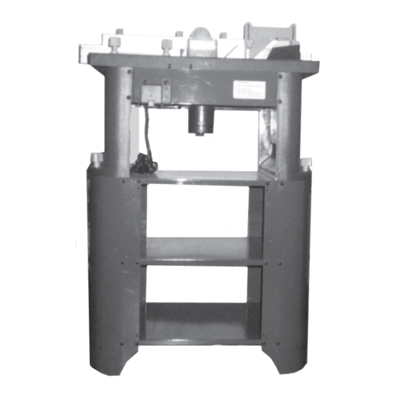
ROUTER WITH FULL SIZE TABLE
Model 91130
ASSEMBLY AND OPERATING INSTRUCTIONS
®
3491 Mission Oaks Blvd., Camarillo, CA 93011
Visit our Web site at: http://www.harborfreight.com
©
®
Copyright
2004 by Harbor Freight Tools
. All rights reserved. No portion of this
manual or any artwork contained herein may be reproduced in any shape or form
without the express written consent of Harbor Freight Tools.
For technical questions or replacement parts, please call 1-800-444-3353.
Advertisement
Table of Contents

Subscribe to Our Youtube Channel
Related Manuals for Central Machinery ROUTER WITH FULL SIZE TABLE 91130

Summary of Contents for Central Machinery ROUTER WITH FULL SIZE TABLE 91130
- Page 1 . All rights reserved. No portion of this manual or any artwork contained herein may be reproduced in any shape or form without the express written consent of Harbor Freight Tools. For technical questions or replacement parts, please call 1-800-444-3353.
-
Page 2: Product Specifications
When unpacking, check to make sure all the parts shown on the Parts Lists on pages 26 and 27 are included. If any parts are missing or broken, please call Harbor Freight Tools at the number shown on the cover of this manual as soon as possible. - Page 3 Keep bystanders, children, and visitors away while operating a power tool. Distractions can cause you to lose control. Protect others in the work area from debris such as chips and sparks. Provide barriers or shields as needed. Grounded tools must be plugged into an outlet properly installed and grounded in accordance with all codes and ordinances.
- Page 4 Dress properly. Do not wear loose clothing or jewelry. Contain long hair. Keep your hair, clothing, and gloves away from moving parts. Loose clothes, jewelry, or long hair can be caught in moving parts. Avoid accidental starting. Be sure the Power Switch is off before plugging in.
- Page 5 Maintain labels and nameplates on the Router. These carry important information. If unreadable or missing, contact Harbor Freight Tools for a replace- ment. Do not force the equipment. This Router will do the work better and safer at the speed and capacity for which it was designed.
- Page 6 Allow the router bit to spin up to full speed before feeding wood into it. When turning off the Router, allow the router bit to spin down and stop on its own. Do not press against the router bit to stop it.
- Page 7 Maintain this product with care. Keep the Router clean and dry for better and safer performance. Make sure to keep router bits sharp and clean. For your safety, service and maintenance should be performed regularly by a qualified technician. Use the right tool or attachment for the right job. Do not attempt to force a small tool or attachment to do the work of a larger industrial tool or attachment.
- Page 8 Improperly connecting the grounding wire can result in the risk of electric shock. Check with a qualified electrician if you are in doubt as to whether the outlet is properly grounded. Do not modify the power cord plug provided with the tool.
- Page 9 DOUBLE INSULATED TOOLS: TOOLS WITH TWO PRONG PLUGS Tools marked “Double Insulated” do not require grounding. They have a special double insulation system which satisfies OSHA requirements and complies with the applicable standards of Underwriters Laboratories, Inc., the Canadian Standard Association, and the National Electrical Code. (See Figure B.) Double insulated tools may be used in either of the 120 volt outlets shown in the following illustration.
- Page 10 If you are using an extension cord outdoors, make sure it is marked with the suffix “W-A” (“W” in Canada) to indicate it is acceptable for outdoor use. Make sure your extension cord is properly wired and in good electrical condition. Always replace a damaged extension cord or have it repaired by a qualified electrician before using it.
-
Page 11: Product Features
Part # Description Power Switch (not shown) Safety Cover Large Lock Knob Main Table Feather Board Variable Speed Adjustment Lower Fence Fence Lock Knob Fence Adjusting Knob (16C) (2C) (8C) (21B) (20B) (10B / 9B) (8B) (28B) (14B) (8C) (26C) (13C) SKU 91130 For technical questions, please call 1-800-444-3353. - Page 12 NOTE: For additional references to the parts listed in the following pages, refer to the Assembly Diagrams on pages 28, 29, 30, 31, and 32. To Assemble The Base: Place one Table (8A) upside down on a level floor surface. Attach a Support Board 1 (2A) to opposite corners of the Table, and attach a Support Board 2 (1A) to the two remaining opposite corners of the Table using Screws (3A), Washers (6A), and Plastic Nuts (7A).
- Page 13 With assistance, turn the assembled Base right side up . (See Figure F.) With assistance, move the assembled Base to the floor surface where the Router will be used. NOTE: Make sure the floor surface is dry, flat, level, and sturdy enough to support the weight of the Router, workpieces, and any additional tools and equipment.
- Page 14 To Attach The Mid-Section To The Body: With assistance, place the Mid-Section of the Router Table on top of the Base. (See Figure H.) Align the two mounting holes at the bottom of each Support Leg (12B) with the two mounting holes at each end of the Table (8A). (See Figure H.)
- Page 15 LEFT SIDE BOARD (17B) mounting holes in the Corner Washers and Support Legs. (See Figure J.) Insert eight Square Head Bolts (22B) downward through the eight mounting holes in the Main Table (20B) and through the eight mounting holes in the Corner Washers (19B) and Support Legs (12B).
- Page 16 Screw a Nut (24B) downward on each of the eight Hex Screws (23B). Insert the Hex Screws downward through the eight mounting holes located on the Main Table (20B). Make sure the Nuts are above the mounting holes. Then, screw a Nut (24B) upward on each of the eight Hex Screws to secure the Hex Screws to the Main Table.
- Page 17 Position the Upper Fence (16C) on the Main Table (20B). Use two Screws (9C) to attach a Fence Support (10C) to the back of the Upper Fence (16C), making sure to use two of the outermost pre-fitted Nuts (11C) in the channel of the Upper Fence.
- Page 18 Power Cord/Plug (1B) is unplugged from its electrical outlet before making any adjustments to the Router Table. The Router is equipped with a 1/4” Collet (18D) and a 1/2” Collet (24D). The Collet (18D, 24D) may need to be changed to allow use of larger or smaller diameter router bits (not included).
- Page 19 Remove the existing Collet (18D, 24D) from the assembly, and make sure to install the correct size Collet (1/4” or 1/2”) for the router bit to be used. Then, finger tighten the Collet Nut (19D) back onto the assembly. (See Figure O.)
- Page 20 Make sure to insert the shaft of the router bit all the way into the Collet (18D, 24D). (See Figure P.) Tighten the Collet Nut (19D) by pulling and holding the Spindle Lock Lever (22E) forward while screwing the Collet Nut in a clockwise direction.
- Page 21 To determine the depth of cut, use a ruler to measure the distance between the base of the Main Table (20B) and the tip of the router bit. Once the depth of cut is acquired, align the Height Adjustment Lock (23D) and turn the Lock in a clockwise direction to lock.
- Page 22 Attach the second Feather Board (21B) horizontally to the Main Table (20B). To do so, insert two Square Head Screws (11B) upward through the Feather Board. Then slide the head of both Screws into the keyhole slot located in the channel used for the Miter Gauge (27C).
- Page 23 Knobs (13C). (See Figure T.) To Adjust The Speed (RPM): NOTE: Using the correct speed for the job increases the life of the router bit and can also affect the surface finish on the workpiece being cut. The Router Table features a Variable Speed Adjustment (28B) and may be adjusted from approxi- mately 8,400 RPM to 27,800 RPM (no load).
- Page 24 Depress the Key (8B), and lift up on the Safety Cover (10B). Then, depress the Power Switch (9B) to its “ON” position. (See Figure U.) To turn off the Router Table, simply depress the Safety Cover (10B) to snap it shut. This pushes the “OFF” button underneath the Safety Cover and cuts off the power.
- Page 25 Router Table, particularly, the machine’s Dust Port (26C) and Main Table (20B), Then, use a premium quality, lightweight machine oil to lubricate all mov- ing parts. Do not use solvents or caustic agents to clean the Router Table. PLEASE READ THE FOLLOWING CAREFULLY THE MANUFACTURER AND/OR DISTRIBUTOR HAS PROVIDED THE PARTS LIST AND ASSEMBLY DIAGRAM IN THIS MANUAL AS A REFERENCE TOOL ONLY.
- Page 26 Part # Description Support Board 2 Support Board 1 Screw (M5 x 12) Support Leg 1 Leg Washer Part # Description Power Cord & Plug Cord Clip Cord Protector Switch Box Base Plastic Nail Locking Buckle Plastic Screw (2.9 x 9) Power Switch Safety Cover Square Head Screw (M6 x 40) 6...
- Page 27 Part # Description Screw (M4 x 10) Plastic Lock Nut Washer (4) End Running Knot Slip Knot Snail Knot Block Ring (45) Large Spring Slip Groove Turning Piece Steel Bead (5) Locking Piece Partial Axis Height Adjusting Ring Part # Description Plastic Bolt (M3.5 x 25) Fan Cover...
- Page 28 ASSEMBLY DIAGRAM A SKU 91130 For technical questions, please call 1-800-444-3353. Page 28...
- Page 29 ASSEMBLY DIAGRAM B SKU 91130 For technical questions, please call 1-800-444-3353. Page 29...
- Page 30 ASSEMBLY DIAGRAM C SKU 91130 For technical questions, please call 1-800-444-3353. Page 30...
- Page 31 ASSEMBLY DIAGRAM D SKU 91130 For technical questions, please call 1-800-444-3353. Page 31...
- Page 32 ASSEMBLY DIAGRAM E SKU 91130 For technical questions, please call 1-800-444-3353. Page 32...
Need help?
Do you have a question about the ROUTER WITH FULL SIZE TABLE 91130 and is the answer not in the manual?
Questions and answers