Table of Contents
Advertisement
Advertisement
Table of Contents

Related Manuals for thomann Stage TRI LED Bundle Complete


Summary of Contents for thomann Stage TRI LED Bundle Complete
- Page 1 Stage TRI LED Bundle Complete LED lighting set user manual...
- Page 2 Musikhaus Thomann Thomann GmbH Hans-Thomann-Straße 1 96138 Burgebrach Germany Telephone: +49 (0) 9546 9223-0 E-mail: info@thomann.de Internet: www.thomann.de 18.02.2016, ID: 238663 (V2)
-
Page 3: Table Of Contents
Connections and controls........................24 Operation..............................32 7.1 Starting up the device........................32 7.2 Main menu............................32 7.3 Menu overview..........................41 7.4 Functions in 2-channel DMX mode (d.-P5)................44 7.5 Functions in 3-channel DMX mode (d.-P1)................46 Stage TRI LED Bundle Complete... - Page 4 Table of contents 7.6 Functions in 4-channel DMX mode (d.-P2)................47 7.7 Functions in 7-channel DMX mode (d.-P7)................47 7.8 Functions in 8-channel DMX mode (d.-P3) ................50 7.9 Functions in 14-channel DMX mode (d.-P4)................51 7.10 Functions in 15-channel DMX mode (d.-P6)................ 53 7.11 Functions of foot switch......................
-
Page 5: General Notes
If you sell the unit please make sure that the buyer also receives this manual. Our products are subject to a process of continuous development. Thus, they are subject to change. Stage TRI LED Bundle Complete... -
Page 6: Further Information
General notes 1.1 Further information On our website (www.thomann.de) you will find lots of further information and details on the following points: Download This manual is also available as PDF file for you to download. Use the search function in the electronic version to find the topics of Keyword search interest for you quickly. -
Page 7: Notational Conventions
References to other locations in this manual are identified by an arrow and the specified page number. In the electronic version of the manual, you can click the cross-reference to jump to the specified location. Example: See Ä ‘Cross-references’ on page 7. Stage TRI LED Bundle Complete... -
Page 8: Symbols And Signal Words
General notes 1.3 Symbols and signal words In this section you will find an overview of the meaning of symbols and signal words that are used in this manual. Signal word Meaning DANGER! This combination of symbol and signal word indicates an immediate dangerous situation that will result in death or serious injury if it is not avoided. - Page 9 General notes Warning signs Type of danger Warning – high-voltage. Warning – hot surface. Warning – danger zone. Stage TRI LED Bundle Complete...
-
Page 10: Safety Instructions
Safety instructions Safety instructions Intended use This device is intended to be used as an electronic illumination effect using LED technics. The device is designed for professional use and is not suitable for use in households. Use the device only as described in this user manual. Any other use or use under other operating con‐ ditions is considered to be improper and may result in personal injury or property damage. - Page 11 DANGER! Electric shock caused by short-circuit Do not modify the mains cable or the plug. Failure to do so could result in electric shock/death or fire. If in doubt, seek advice from a registered electrician. Stage TRI LED Bundle Complete...
- Page 12 Safety instructions DANGER! Electric shock caused by high voltages inside Within the device there are areas where high voltages may be present. Never remove any covers. There are no user-serviceable parts inside. Do not use the device if covers, protectors or optical components are missing or damaged.
- Page 13 WARNING! Risk of burns The surface of the device can become very hot during operation. Do not touch the device with bare hands during operation, and after switching off wait for at least 15 minutes. Stage TRI LED Bundle Complete...
- Page 14 Safety instructions NOTICE! Risk of fire Do not cover the device nor any ventilation slots. Do not place the device near any direct heat source. Keep the device away from naked flames. NOTICE! Operating conditions This device has been designed for indoor use only. To prevent damage, never expose the device to any liquid or moisture.
- Page 15 Failure to do so could result in damage to the device and possibly injure the user. Unplug the device before electrical storms occur and when it is unused for long periods of time to reduce the risk of electric shock or fire. Stage TRI LED Bundle Complete...
-
Page 16: Features
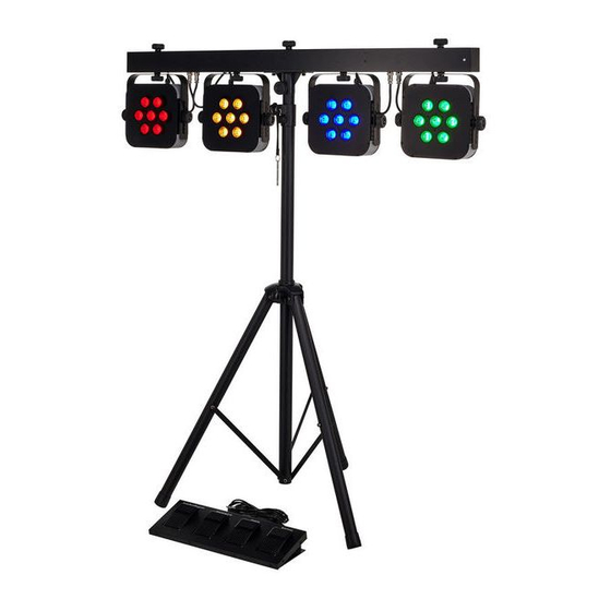
Features Features The LED lighting set is especially suited for professional lighting tasks, e.g. during events, on rock music stages, in theatre and musical productions. It is characterized by a low power con‐ sumption and long life. Special features of this device: 4 LED spots with 7 tri-colour LEDs Control via DMX (7 different modes), buttons and display on the unit, foot switch and infrared remote control (optional available) -
Page 17: Installation
NOTICE! Risk of overheating Always ensure sufficient ventilation. The ambient temperature must always be below 40 °C (104 °F). Stage TRI LED Bundle Complete... - Page 18 Installation NOTICE! Use of stands When mounting the device onto a stand, ensure that the stand is in a safe and stable position and that the weight of the device does not exceed the maximum permissible load capacity of the stand. NOTICE! Possible data transmission errors For error-free operation make use of dedicated DMX cables and do not use ordi‐...
- Page 19 Locking screws to fix the height and angle of inclination. Locking screw for fixing the spot on the T-bar and for horizontal alignment (direction of the beam). Stage TRI LED Bundle Complete...
- Page 20 Installation Electrical connection of the spot on the T-bar (pre-assembled). 1/4" phone socket to connect the foot switch unit. The cable with the phone jack is pre-as on the foot switch unit. LED lighting set...
-
Page 21: Setup
Setup Setup Create all connections while the device is off. Use the shortest possible high-quality cables for all connections. Take care when running the cables to prevent tripping hazards. Stage TRI LED Bundle Complete... - Page 22 Setup Connections in DMX mode Connect the DMX input of the device to the DMX output of a DMX controller or another DMX device. Connect the output of the first DMX device to the input of the second one, and so on to form a daisy chain.
- Page 23 Connect the DMX output of the master device to the DMX input of the first slave device. Then connect the DMX output of the first slave device to the DMX input of the second slave device and so on. Stage TRI LED Bundle Complete...
-
Page 24: Connections And Controls
Connections and controls Connections and controls Front panel LED lighting set... - Page 25 Selects an option of the respective operating mode, confirms the set value. 5 Button [Up] Increases the displayed value by one. 6 Button [Down] Decreases the displayed value by one. 7 [DMX In] / [DMX Out] DMX input or output. Stage TRI LED Bundle Complete...
- Page 26 Connections and controls 8 [Footswitch Input] 1/4" phone socket to connect the foot switch unit. 9 Infrared sensor for the IR remote control signal. LED lighting set...
- Page 27 Connections and controls Foot switch unit Stage TRI LED Bundle Complete...
- Page 28 Connections and controls 10 Foot switch [Auto Run] Activates the automatic mode (playback of the preprogrammed automatic shows). 11 Foot switch [Sound Active] Activates the sound control mode (playback of the sound-controlled automatic shows). 12 Foot switch [Freeze] Freezes the running show or continues it after a break. 13 Foot switch [Blackout] Activates or deactivates the blackout for all LEDs.
- Page 29 Connections and controls Infrared remote control (optional available) Stage TRI LED Bundle Complete...
- Page 30 Connections and controls 14 [AUTO] Activates the automatic mode. 15 [PRG] Activates the preprogrammed automatic show mode. Use the [+] and [–] buttons to select the desired programme. 16 [ON/OFF] Activates/deactivates the device. 17 [SPEED] Activates the setup mode for the programme speed. Use the [+] and [–] buttons to set the speed.
- Page 31 Activates the dimming function for static colours. Use the [+] and [–] buttons to set the value for each static colour. 23 [0 … 9] Numeric keys for the direct selection of static colours. 24 [R], [G], [B], [A], [W] Buttons for selecting the colour hue in dimming operation. Stage TRI LED Bundle Complete...
-
Page 32: Operation
Operation Operation 7.1 Starting up the device Connect the unit to the power grid to start the operation. After a few seconds the display shows a running reset. Then the unit is ready for use. 7.2 Main menu Press [Mode] to activate the main menu and select an operating mode. Use [Setup] to select further options. - Page 33 The following table shows the programmes that are available. Programme Description Pr.01 Static colours Pr.02 Colour fading 1 Pr.03 Colour fading 2 Pr.04 Fade in / fade out Pr.05 Colour change 1 Pr.06 Chase 1 Pr.07 Chase 2 Pr.08 Chase 3 Stage TRI LED Bundle Complete...
- Page 34 Operation Programme Description Pr.09 Chase 4 Pr.10 Chase 5 Pr.11 Chase 6 Pr.12 Colour change 2 Pr.13 Chase 7 Pr.14 Chase 8 Settings for programme 01: For ‘Pr.01’ , you can choose from 7 colours or blackout. Press [Setup]. Now use [Up] and [Down] to select one of the colours.
- Page 35 To set the background colour, repeatedly press [Setup] until the display shows ‘1.xxx’ . Now use [Up] and [Down] to select a background colour. To set the running colour, repeatedly press [Setup] until the display shows ‘2.xxx’ . Now use [Up] and [Down] to select a running colour. Stage TRI LED Bundle Complete...
- Page 36 Operation Operating mode ‘Automatic’ Automatic operation can only be activated if the unit is working in stand-alone mode or as master device in a master / slave combination. This setting is only relevant if the unit is not controlled via DMX. Press [Mode] repeatedly until the display shows ‘AUTO’...
- Page 37 Make sure that this number matches the configuration of your DMX controller. The following table shows the highest possible DMX address for the different DMX modes. Mode Highest possible DMX address 2-channel 3-channel 4-channel 7-channel 8-channel 14-channel 15-channel Stage TRI LED Bundle Complete...
- Page 38 Operation Press [Setup]. Use [Up] and [Down] to select one of the following DMX operating modes: ‘d.-P1’ (3 channels) ‘d.-P2’ (4 channels) ‘d.-P3’ (8 channels) ‘d.-P4’ (14 channels) ‘d.-P5’ (2 channels) ‘d.-P6’ (15 channels) ‘d.-P7’ (7 channels) Operating mode ‘Slave’ This setting is only relevant if the unit is operated as slave device in a master / slave configura‐...
- Page 39 Press [Mode] repeatedly until the display shows ‘SU.xx’ . This will activate a sound-controlled automatic show. Press [Setup]. Now you can adjust the sound-control sensitivity. Use [Up] and [Down] to select a value between 0 (low sensitivity) and 31 (high sensitivity), the display shows ‘SU.00’ … ‘SU.31’ . Stage TRI LED Bundle Complete...
- Page 40 Operation Constant unicoloured pattern A constant unicoloured pattern can only be activated if the unit is working in stand-alone mode or as master device in a master / slave combination. This setting is only relevant if the unit is not controlled via DMX. Press [Mode] repeatedly until the display shows ‘Colr’...
-
Page 41: Menu Overview
Operation 7.3 Menu overview Stage TRI LED Bundle Complete... - Page 42 Operation LED lighting set...
- Page 43 Operation Stage TRI LED Bundle Complete...
-
Page 44: Functions In 2-Channel Dmx Mode (D.-P5)
Operation 7.4 Functions in 2-channel DMX mode (d.-P5) Channel Value Function 0…9 LEDs off 10…19 Constant unicoloured pattern in red for all LEDs 20…29 Constant unicoloured pattern in yellow for all LEDs 30…39 Constant unicoloured pattern in green for all LEDs 40…49 Constant unicoloured pattern in cyan for all LEDs 50…59... - Page 45 Preprogrammed automatic show no. 12 220…229 Preprogrammed automatic show no. 13 230…239 Preprogrammed automatic show no. 14 240…255 Sound-controlled show Function depends on channel 1 setting Channel 1 = 0…79 No function Channel 1 = 80…239 0…255 Increasing speed Stage TRI LED Bundle Complete...
-
Page 46: Functions In 3-Channel Dmx Mode (D.-P1)
Operation Channel Value Function Channel 1 = 240…225 0…255 Increasing sensitivity 7.5 Functions in 3-channel DMX mode (d.-P1) Channel Value Function 0…255 Intensity red (0 % to 100 %) for all LEDs 0…255 Intensity green (0 % to 100 %) for all LEDs 0…255 Intensity blue (0 % to 100 %) for all LEDs LED lighting set... -
Page 47: Functions In 4-Channel Dmx Mode (D.-P2)
Value Function 0…255 Intensity red (0 % to 100 %) for all LEDs 0…255 Intensity green (0 % to 100 %) for all LEDs 0…255 Intensity blue (0 % to 100 %) for all LEDs Stage TRI LED Bundle Complete... - Page 48 Operation Channel Value Function 0…9 LEDs off 10…19 Constant unicoloured pattern in red for all LEDs 20…29 Constant unicoloured pattern in yellow for all LEDs 30…39 Constant unicoloured pattern in green for all LEDs 40…49 Constant unicoloured pattern in cyan for all LEDs 50…59 Constant unicoloured pattern in blue for all LEDs 60…69...
- Page 49 240…255 Sound-controlled show Function depends on channel 4 setting Channel 4 = 0…79 No function Channel 4 = 80…239 0…255 Increasing speed Channel 4 = 240…255 0…255 Increasing sensitivity Function depends on channel 4 setting Stage TRI LED Bundle Complete...
-
Page 50: Functions In 8-Channel Dmx Mode (D.-P3)
Operation Channel Value Function Channel 4 = 0…9 No function Channel 4 = 10…255 0…255 Strobe effect, increasing speed 0…255 Dimmer (0 % to 100 %) 7.8 Functions in 8-channel DMX mode (d.-P3) Channel Value Function 0…255 Intensity red (0 % to 100 %) for all LEDs of spots 1 and 2 0…255 Intensity green (0 % to 100 %) for all LEDs of spots 1 and 2 0…255... -
Page 51: Functions In 14-Channel Dmx Mode (D.-P4)
Intensity red (0 % to 100 %) for all LEDs of spot 1 0…255 Intensity green (0 % to 100 %) for all LEDs of spot 1 0…255 Intensity blue (0 % to 100 %) for all LEDs of spot 1 Stage TRI LED Bundle Complete... - Page 52 Operation Channel Value Function 0…255 Intensity red (0 % to 100 %) for all LEDs of spot 2 0…255 Intensity green (0 % to 100 %) for all LEDs of spot 2 0…255 Intensity blue (0 % to 100 %) for all LEDs of spot 2 0…255 Intensity red (0 % to 100 %) for all LEDs of spot 3 0…255...
-
Page 53: Functions In 15-Channel Dmx Mode (D.-P6)
Intensity green (0 % to 100 %) for all LEDs of spot 1 0…255 Intensity blue (0 % to 100 %) for all LEDs of spot 1 0…255 Intensity red (0 % to 100 %) for all LEDs of spot 2 Stage TRI LED Bundle Complete... -
Page 54: Functions Of Foot Switch
Operation Channel Value Function 0…255 Intensity green (0 % to 100 %) for all LEDs of spot 2 0…255 Intensity blue (0 % to 100 %) for all LEDs of spot 2 0…255 Intensity red (0 % to 100 %) for all LEDs of spot 3 0…255 Intensity green (0 % to 100 %) for all LEDs of spot 3 0…255... -
Page 55: Remote Control Functions
Press the foot switch [Blackout] for a blackout (all LEDs off). Press it again to return to normal operation. 7.12 Remote control functions The button functions of the remote control are described in section Ä ‘Infrared remote control (optional available)’ on page 29. Stage TRI LED Bundle Complete... - Page 56 Operation Direct selection of a static colour Use the numeric keys of the remote control to select a static colour directly. This setting is only relevant if the device is not controlled via DMX. Value Static colour Cyan Purple Pink Orange Cool white Light red...
-
Page 57: Reset To Factory Defaults
Reset to factory defaults Proceed as follows to restore the factory default settings: Switch off the device. Simultaneously press [Mode] and [Setup] and switch on the device, holding the two but‐ tons for approx. 2 seconds. Stage TRI LED Bundle Complete... -
Page 58: Technical Specifications
Technical specifications Technical specifications Number of DMX channels 2, 3, 4, 7, 8, 14 or 15 channels, depending on operating mode Illuminant 28 × 3-W tri-colour LEDs (7 × per spot) Dispersion angle approximately 40° Operating supply voltage 100 … 240 V , 50 … 60 Hz Power consumption 100 W Fuse... -
Page 59: Plug And Connection Assignment
The unit offers a 3-pin XLR socket for DMX output and a 3-pin XLR plug for DMX input. Please refer to the drawing and table below for the pin assignment of a suitable XLR plug. Configuration Ground, shielding Signal inverted (DMX–, ‘cold signal’) Signal (DMX+, ‘hot signal’) Stage TRI LED Bundle Complete... -
Page 60: Cleaning
Cleaning Cleaning Optical lenses Clean the optical lenses, that are accessible from the outside, regularly in order to optimize the light output. The frequency of cleaning depends on the operating environment: wet, smoky or particularly dirty surroundings can cause more accumulation of dirt on the optics of the device. -
Page 61: Protecting The Environment
Batteries must not be disposed of as domestic waste or thrown into fire. Dispose of the bat‐ teries according to national or local regulations regarding hazardous waste. To protect the environment, dispose of empty batteries at your retail store or at appropriate collection sites. Stage TRI LED Bundle Complete... - Page 62 Protecting the environment Disposal of your old device This product is subject to the European Waste Electrical and Electronic Equipment Directive (WEEE). Do not dispose with your normal household waste. Dispose this device through an approved waste disposal firm or through your local waste facility.
- Page 64 Musikhaus Thomann · Hans-Thomann-Straße 1 · 96138 Burgebrach · Germany · www.thomann.de...
Need help?
Do you have a question about the Stage TRI LED Bundle Complete and is the answer not in the manual?
Questions and answers