Table of Contents
Advertisement
UTY-LNHY
UTY-LNHG
INSTALLATION MANUAL
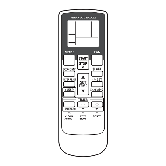
WIRELESS REMOTE CONTROLLER
For authorized service personnel only.
INSTALLATIONSANLEITUNG
KABELLOSE FERNBEDIENUNG
Nur für autorisiertes Fachpersonal.
MANUEL D'INSTALLATION
TÉLÉCOMMANDE SANS FIL
Pour le personnel d'entretien autorisé uniquement.
MANUAL DE INSTALACIÓN
MANDO A DISTANCIA INALÁMBRICO
Únicamente para personal de servicio autorizado.
MANUALE DI INSTALLAZIONE
UNITÀ DI CONTROLLO SENZA FILI
A uso esclusivo del personale tecnico autorizzato.
ΕΓΧΕΙΡΙΔΙΟ ΕΓΚΑΤΑΣΤΑΣΗΣ
ΑΣΥΡΜΑΤΟ ΤΗΛΕΧΕΙΡΙΣΤΗΡΙΟ
Μόνο για εξουσιοδοτημένο τεχνικό προσωπικό.
MANUAL DE INSTALAÇÃO
CONTROLO REMOTO SEM FIOS
Apenas para pessoal de assistência autorizado.
РУКОВОДСТВО ПО УСТАНОВКЕ
БЕСПРОВОДНОЙ ПУЛЬТ ДИСТАНЦИОННОГО УПРАВЛЕНИЯ
Только для авторизованного обслуживающего персонала.
KURULUM KILAVUZU
KABLOSUZ UZAKTAN KUMANDA
Yalnızca yetkili servis personeli için.
仅针对授权的专业维修人员。
安装说明书
无线遥控器
PART NO. 9371972046-07
Advertisement
Table of Contents

Summary of Contents for AirStage UTY-LNHY
-
Page 1: Installation Manual
Pour le personnel d’entretien autorisé uniquement. MANUAL DE INSTALACIÓN MANDO A DISTANCIA INALÁMBRICO Únicamente para personal de servicio autorizado. MANUALE DI INSTALLAZIONE UTY-LNHY UNITÀ DI CONTROLLO SENZA FILI UTY-LNHG A uso esclusivo del personale tecnico autorizzato. ΕΓΧΕΙΡΙΔΙΟ ΕΓΚΑΤΑΣΤΑΣΗΣ ΑΣΥΡΜΑΤΟ ΤΗΛΕΧΕΙΡΙΣΤΗΡΙΟ... -
Page 2: Table Of Contents
INSTALLATION MANUAL This mark indicates procedures which, if PART NO. 9371972046-07 CAUTION improperly performed, might possibly result in WIRELESS REMOTE CONTROLLER personal harm to the user or damage to property. CONTENTS Do not install in any place at a temperature of more than 40 °C or less than 0 °C or exposed to direct sunlight. -
Page 3: Turning On The Power
CAUTION 3. TURNING ON THE POWER Fixing of the holder cover with the screws in the standard parts may be (1) Throw the circuit breakers for the indoor unit and outdoor unit. unsuitable if the wall or ceiling material is weak. If so, prepare screws (2) M a k e s u r e t h a t t h e o p e r a t i o n i n d i c a t o r l a m p a n d t i m e r suitable for the wall or ceiling material, and fi... -
Page 4: Address Setting
■ Switching selection of address setting mode 5. ADDRESS SETTING (3) Press and hold the “MANUAL/AUTO” button for 3 seconds. Address setting method can be selected from 3 options, outdoor unit, indoor unit and remote controller. OPERATION Refer to the installation manual of outdoor unit or indoor unit when set up indicator (Green) Pi Pi Pi from the outdoor unit or the indoor unit. - Page 5 ■ Address setting (12) Indoor unit will display the indoor unit address data number on “TIMER ” (ORANGE) and “FILTER ” (RED) light. Indoor unit address setting (7) Press the “MODE” button to access the address setting mode. Flashing times of Continuously Flashing times of address numbers...
- Page 6 (17) Press the “ ” or the “ ” buttons to adjust the address data. The ■ Completion of address setting mode refrigerant circuit address range is between 00 and 99. Each time the (21) Press and hold the “MANUAL/AUTO” button for 3 seconds. “MODE”...
-
Page 7: Function Setting
Refrigerant circuit address setting 6. FUNCTION SETTING (25) Make sure the function number is • This procedure changes to the function settings used to control the indoor “02”. Refer to (15). Press the “TIMER unit according to the installation conditions. Incorrect settings can cause the “TIMER set (-)”... - Page 8 (5) Press the “TIMER Correct code: Case1 : When setting number is 1 digit. MODE” button to (11-1) Indoor unit will display the function setting number on “OPERATION” Pi Pi send the code to (GREEN), “TIMER ” (ORANGE) and “FILTER ”...
- Page 9 Confi rmation of function setting Case1 : When setting number is 1 digit. (12) Press the “TIMER set (+)” button. (Example) Function number : 30, Setting number : 01 0.5sec ON / 0.5sec OFF OPERATION LAMP (GREEN) “TIMER set (+)” 3 times 3 times PiPi...
-
Page 10: Selecting The Remote Controller Signal Code
Indoor Unit Setting (Example) 7. SELECTING THE REMOTE CONTROLLER SIGNAL CODE PC board and switch layout in each indoor unit are different. Refer to the installation manual of each indoor unit. When 2 or more air conditioners are installed in a room and the remote controller is operating an air conditioner other than the one you wish to set, change the signal code of the remote controller to operate only the air DIP SW (SET3)


Need help?
Do you have a question about the UTY-LNHY and is the answer not in the manual?
Questions and answers