Table of Contents
Advertisement
UTY-RLRY
UTY-RLRG
TM
OPERATING MANUAL
WIRED REMOTE CONTROLLER
Keep this manual for future reference.
BEDIENUNGSANLEITUNG
Bewahren Sie dieses Handbuch für eine spätere Bezugnahme auf.
MODE D'EMPLOI
Conservez ce manuel pour pour toute référence ultérieure.
MANUAL DE FUNCIONAMIENTO
MANDO A DISTANCIA CON CABLE
Conserve este manual para posibles consultas futuras.
MANUALE DI ISTRUZIONI
UNITÀ DI CONTROLLO A FILO
Conservare questo manuale per consultazione futura.
ΕΓΧΕΙΡΙΔΙΟ ΛΕΙΤΟΥΡΓΙΑΣ
ΕΝΣΥΡΜΑΤΟ ΤΗΛΕΧΕΙΡΙΣΤΗΡΙΟ
Διατηρήστε το παρόν εγχειρίδιο για μελλοντική αναφορά.
MANUAL DE FUNCIONAMENTO
CONTROLO REMOTO COM FIOS
Guarde este manual para consulta futura.
РУКОВОДСТВО ПО ЭКСПЛУАТАЦИИ
ПРОВОДНОЙ ПУЛЬТ ДИСТАНЦИОННОГО УПРАВЛЕНИЯ
Сохраните данное руководство для последующего использования.
KULLANIM KILAVUZU
KABLOLU UZAKTAN KUMANDA
Bu kılavuzu ileride başvurmak üzere saklayın.
KABEL-FERNBEDIENUNG
TÉLÉCOMMANDE FILAIRE
PART NO. 9380859031
Advertisement
Table of Contents

Related Manuals for AirStage UTY-RLRG


Summary of Contents for AirStage UTY-RLRG
- Page 1 Conservez ce manuel pour pour toute référence ultérieure. MANUAL DE FUNCIONAMIENTO MANDO A DISTANCIA CON CABLE UTY-RLRY Conserve este manual para posibles consultas futuras. UTY-RLRG MANUALE DI ISTRUZIONI UNITÀ DI CONTROLLO A FILO Conservare questo manuale per consultazione futura. ΕΓΧΕΙΡΙΔΙΟ ΛΕΙΤΟΥΡΓΙΑΣ...
-
Page 2: Table Of Contents
INTRODUCTION OPERATING MANUAL PART NO. 9380859031 ■ SAFETY PRECAUTIONS WIRED REMOTE CONTROLLER • The “SAFETY PRECAUTIONS” indicated in the manual CONTENTS contain important information pertaining to your safety. Be sure to observe them. INTRODUCTION • Request the user to keep the manual on hand for future ■... -
Page 3: System Outline
2-wire remote controller address: ■ SYSTEM OUTLINE This ID is used for control and is allotted to remote Terminology controllers in R.C. Group formed by 2-wire type remote controllers and indoor units. The ID consists of 3-digit System related terms “System number”... -
Page 4: Overview And Basic Operations
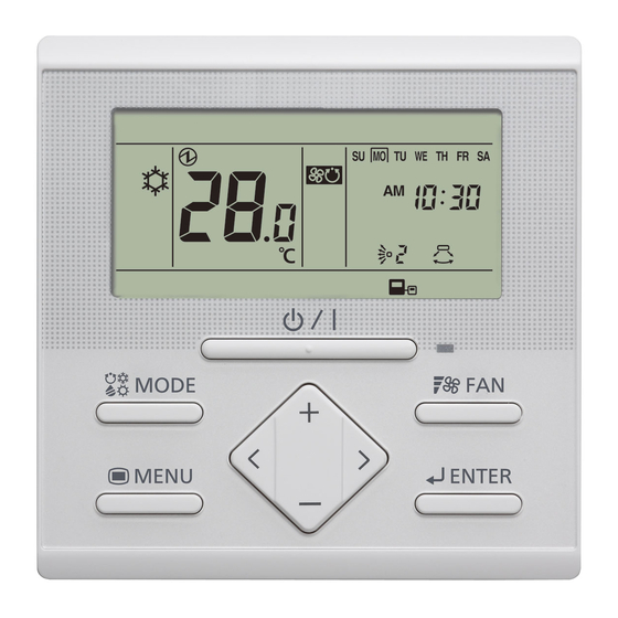
1-5. FAN Button 1. OVERVIEW AND BASIC OPERATIONS By pressing the [ ] button will switch between fan speeds. Auto High 1-1. 1-2. 1-3. 1-5. 1-4. Note 1-7. 1-6. If Dry is selected, the fan speed can be set to Auto only. 1-9. -
Page 5: Menu Settings
2. MENU SETTINGS Notes • Set airfl ow direction with the remote controller. Attempt- (1) Press the [ ] button. Setting item selection ing to move the airfl ow direction louvre manually could screen is displayed. result in improper operation; in this case, stop operation (2) Select the icon of the item to be set with the [ ] or [ and restart. -
Page 6: Current Time Setting
2-5. Filter Sign Reset (3) Adjust the time with the [ or [ ] buttons. (1) Select the icon of the fi lter sign reset in Menu Settings. Then Press the [ button. Note (2) When the [ ] button is pressed, the display Time can be set in 0.5 H units from 0.5 H to 3.0 H, after returns to the “Monitor Mode Screen”. -
Page 7: Menu 1 Settings (For Administrator)
3-2. Weekly Timer Setting 3. MENU 1 SETTINGS (for Administrator) Note • This function cannot be used if “The Setting of Using the (1) With “Monitor Mode Current Time” is set to “Not used”. To change to “Used”, Screen” displayed, press consult an authorized service personnel. - Page 8 ● Select a day of the week (or all days) (12) Press the [ button. (3) Select a day of the week with the [ ] or [ buttons. A “ ” appears around the selected day. Notes • If Timer 1 OFF is the following day, Timer 2 cannot be set.
-
Page 9: Set Temp. Range Setting
Notes Set enabled with the [ ] or ] buttons. Then press • The schedule of the selected day of the week is dis- the [ ] button. abled for a period of 1 week from the set day. When the If set to “Enable”, proceed selected day is passed, the schedule for that day of the to (3). -
Page 10: Key Locks
4. KEY LOCKS 5. OPERATING TIPS 5-1. About the Status Icons Notes The contents of the status icon displayed on the “Monitor • The child lock and part lock can be unlocked only when Mode Screen” are as follows. the “Monitor Mode Screen” is displayed. Error •... -
Page 11: Settable Temperature Range
6-2. Specifi cations Heat pump system (a) When a master indoor unit is set in a refrigerant system, Model Name UTY-RLRY/UTY-RLRG only the mode selected at the master indoor unit (*2) Input voltage DC 12 V can be used. (*2: “Fan” cannot be selected at the indoor Power consumption Max.
Need help?
Do you have a question about the UTY-RLRG and is the answer not in the manual?
Questions and answers