Table of Contents
Advertisement
Quick Links
Advertisement
Table of Contents

Related Manuals for IKUSI HTI-404


Summary of Contents for IKUSI HTI-404
- Page 1 Web Interface guide HTI-404 REF. 3864...
- Page 2 Web Interface guide HTI-404...
-
Page 3: Table Of Contents
Index 1. INTRODUCTION ............................4 1.1 General safety instructions ...................4 1.2 Installation enviroment recommendations .............5 1.3 Description of the module HTI-404 ................5 2. HEADEND CONNECTION ........................6 3. COMMUNICATION WITH THE HEADEND ..................6 4. WEB INTERFACE ..........................7 4.1 Headend ..........................7 4.1.1 Overview .......................7... -
Page 4: Introduction
The document describes how the headend is configured. For that, initially the physical mounting is descri- bed. After that, it explains how to connect the user pc to the headend through IKUSI HEADEND DISCOVERY application. Finally, all the menu options of the web interface are described. -
Page 5: Installation Enviroment Recommendations
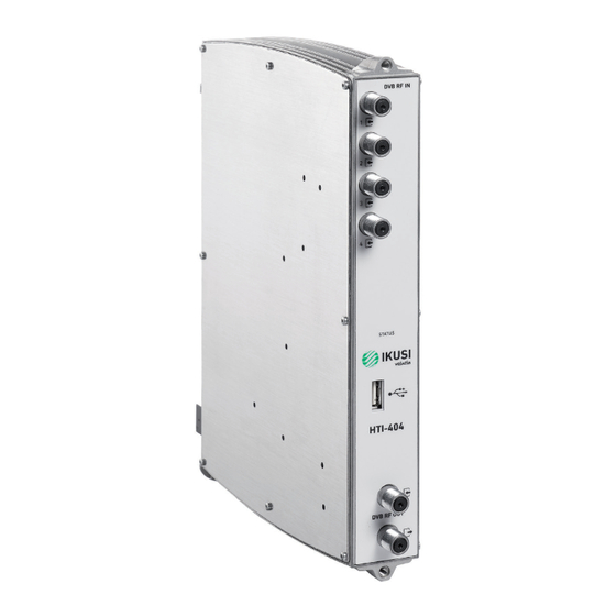
The device should not be used in a very dusty or saline environment. Dust or salt particles and other foreign objects may damage the device. Do not expose the device to extreme vibrations. It may damage the internal components. Description of the module HTI-404 DVB RF IN MSS-0512 Ref. -
Page 6: Headend Connection
3. COMMUNICATION WITH THE HEADEND HTI is configured through a web page generated by the own headend. Use IKUSI HEADEND DISCOVERY application to access this web page without modifying manually the network configuration of your pc. You can download the IKUSI HEADEND DISCOVERY aplication from www.ikusi.tv web page. -
Page 7: Web Interface
Web Interface guide HTI-404 Configure The window will show the name of the connected master module. Push button and the web browser of the PC will open automatically, showing the access page of the headend. NOTE: HTI web interface uses https protocol. It is likely that your browser doesn’t recognize the security certificate generated by the HTI. - Page 8 Web Interface guide HTI-404 This screen shows the whole headend schematically. The essential information of each module inserted in the base-plate is displayed. The master module always corresponds with the module inserted in slot 2, and it appears in white on black background. The remaining modules appear on white background.
-
Page 9: Registering Process
Web Interface guide HTI-404 In addition, through a series of buttons you can perform the following actions: To register a module. To unregister a module. To clone settings from an old module to a new one. To reboot a module. - Page 10 Web Interface guide HTI-404 The registration process is different if it is the result of replacing a module (for example, due to failure). In that case, when placing a new module in the position of one that had been already registered by the headend, the user can choose between to add it without modifying the configuration of the module or to copy the configuration of the module that was previously registered in that slot.
-
Page 11: Reboot And Reset
Web Interface guide HTI-404 4.1.1.2 Reboot and reset Reboot The user can reboot a specific module. To do this, you must push button of that module. On the other hand, if you just want to load the default settings of the module, just as it comes from the... -
Page 12: Internet Access
Web Interface guide HTI-404 Follow the instructions on the screen to make the change of the password (enter the old password, enter Save the new password and confirm the new password) . Finally, push the button. 4.1.2.3 Internet access If you want to access to the headend through internet, you must set previously the connectivity parame- ters of the headend. -
Page 13: Autoscan Dtt Inputs
Web Interface guide HTI-404 In the LNB area, set the parameters of the LNB that you are using (frequency band, local oscillator fre- quency for low polarity and local oscillator frequency for high polarity). In the Multiswitch area you can describe how is the Multiswitch that is being used. To do that, introduce the number of inputs of the multiswitch (in the case there isn’t multiswitch, select 0). -
Page 14: Configuration Backup
Web Interface guide HTI-404 4.1.2.7 Configuration backup The Configuration Backup tab is used to download or upload a copy of the complete configuration of the headend. Thus, you can replicate the configuration of a headend over another one (or over the same one, if, for any mishandling, it reaches to an undesired state). -
Page 15: Output Network Configuration
Web Interface guide HTI-404 4.1.3.1 Output network configuration When selecting this first tab, a window as the following one will be displayed: In this window, the name of the network included in the NIT will be shown, with the value of NID and ONID that are being used. -
Page 16: Modules In Network
Web Interface guide HTI-404 4.1.3.2 Modules in network This tab shows the DVB signaling information of the output carriers of all the modules included in the broadcasting network. Push icon to edit the information of a specific carrier. A window as the following one will open:... -
Page 17: Modules Configuration
Web Interface guide HTI-404 • Information about the RF inputs of each module, such as standard, frequency, status, signal strength or signal quality. • Information about the RF outputs of each module, such as standard, frequency, available space or number of services. - Page 18 Web Interface guide HTI-404 In this window, the four inputs of each HTI are displayed. To configure one of them, select the icon associated with that input. For each input, you must configure if it is enabled or not and what is the reception standard (DVB-S / S2 for satellite, DVB-T / T2 for terrestrial or DVB-C for cable).
- Page 19 Web Interface guide HTI-404 DVB-S/S2 • Frequency (MHz): it allows to select the intermmediate frequency value to be received. • Diseqc input: it allows to select the multiswitch signal (or the LNB signal) to be received. • Sat. Frequency Transponder (MHz): it allows to select the frequency value of the transponder to be received.
-
Page 20: Outputs
Web Interface guide HTI-404 4.2.2 Outputs To configure the output carriers you want to transmit, select Modules Configuration Outputs. A window as the following one will open: In this screen the output configuration of each module is displayed. This configuration is divided into two parts: a global part associated with the module and another part associated with each of the carriers. - Page 21 Web Interface guide HTI-404 To enable an output carrier, select Enabled ON. Otherwise, select OFF. The rest of parameters to configure will depend on the selected standard, in the following way: DVB-T • Frequency (MHz): it allows to select the frequency value of the carrier to be generated.
-
Page 22: Rf Services Configuration
Web Interface guide HTI-404 For informative purposes, the following data will appear in each of the outputs: • Bit Rate (Mbps): it is the capacity of the carrier to transport information, in Mbps. • Min C/N Theoretical (dB): it is the minimum C/N value that the signal must have at the reception point to make possible its demodulation without erroneous bits. - Page 23 Web Interface guide HTI-404 A list with all the services available in that input will appear. In that list, the encrypted services will be identified with the , icon, the radios with the icon and the data services with the icon.
- Page 24 Web Interface guide HTI-404 Repeat the process with all the services that you want to add. The HTI headends also offer the option of presetting backup channels (empty services) that will allow to increase the lineup in the future without the need of launch a scan in the TVs. To create an empty service, push icon in the output where you want to create the backup channel.
- Page 25 Web Interface guide HTI-404 Enter the name you want to assign to the service (in the example, TV HOTEL 1) and push the Save button. When launching a scan in the TVs, all the services will be stored in memory, empty services too. These backup services could be used in the future for conveying new contents, without the need of rescanning the TVs.
- Page 26 Web Interface guide HTI-404 Select the input from which the service will be extracted. In Input Service drop-down select the new con- tent that will be conveyed by the service already scanned in the TVs. Once the service configuration has been modified, push button.
- Page 27 Web Interface guide HTI-404 Enter from which input the service will be extracted, what is its SID (Service Identifier), what name will be assigned to the service and in what output will be broadcasted. To save the changes, push the Save button.
- Page 28 Web Interface guide HTI-404 • To obtain information of the service. Pushing , icon, a window with information about name, SID and LCN will open. • To remove the content of a service. Pushing , icon, the content of the current service will be elimina- ted, becoming an empty service.
-
Page 29: Firmware Management
Web Interface guide HTI-404 The following fields appear in the list of services: • LCN: it is the value of the Logical Channel Number associated with the service. It is an editable value for the user. • SERVICE NAME: it is the name of the service that will be transferred to the TVs. It is an editable value for the user. -
Page 30: Language
Web Interface guide HTI-404 • UPLOAD A FIRMWARE UPDATE: use this option to upload to the headend a firmware version. Select the Add Firmware File firmware through button. After that, push Upload button. Once the firmware has been uploaded, it will appear in the AVAILABLE FIRMWARE VERSION section. -
Page 31: Equipment Recycling
Web Interface guide HTI-404 5. EQUIPMENT RECYCLING RECYCLING OF ELECTRICAL AND ELECTRONIC EQUIPMENT (Applicable in the European Union and in European countries with selective waste collection systems) This symbol on your equipment or its packaging indicates that this product cannot be treated as general domestic waste and must be handed in at the corresponding point of collection for electric and electronic equipment. - Page 32 Paseo Miramón, 170 20014 San Sebastián Gipuzkoa, España Tel.: +34 943 44 89 44 Fax: +34 943 44 88 20 television@ikusi.com www.ikusi.tv Web Interface guide HTI-404_en...
Need help?
Do you have a question about the HTI-404 and is the answer not in the manual?
Questions and answers