ATEN VM3200 User Manual
32x32 modular matrix switch
Hide thumbs
Also See for VM3200:
- Quick start manual (2 pages) ,
- User manual (209 pages) ,
- Manual (2 pages)
Table of Contents
Advertisement
Quick Links
32x32 Modular Matrix Switch
4-Port 3G-SDI Input Board
4-Port HDBaseT Input / Output Board
VM7514 / VM8514
4-Port HDMI Input / Output Board
VM7804 / VM8804
4-Port DVI Input / Output Board
VM7604 / VM8604
4-Port VGA Input Board
HDMI HDBaseT Lite Receiver with Scaler
VM3200
User Manual
VM7404
VM7104
VE805R
www.aten.com
Advertisement
Table of Contents

Related Manuals for ATEN VM3200


Summary of Contents for ATEN VM3200
- Page 1 32x32 Modular Matrix Switch VM3200 User Manual 4-Port 3G-SDI Input Board VM7404 4-Port HDBaseT Input / Output Board VM7514 / VM8514 4-Port HDMI Input / Output Board VM7804 / VM8804 4-Port DVI Input / Output Board VM7604 / VM8604 4-Port VGA Input Board...
-
Page 2: Rohs
Modular Matrix Solution User Manual EMC Information FEDERAL COMMUNICATIONS COMMISSION INTERFERENCE STATEMENT This equipment has been tested and found to comply with the limits for a Class A digital device, pursuant to Part 15 of the FCC Rules. These limits are designed to provide reasonable protection against harmful interference when the equipment is operated in a commercial environment. -
Page 3: Sj/T 11364-2006
Modular Matrix Solution User Manual SJ/T 11364-2006 The following contains information that relates to China. -
Page 4: User Information
86-400-810-0-810 Japan 81-3-5615-5811 Korea 82-2-467-6789 North America 1-888-999-ATEN ext 4988 United Kingdom 44-8-4481-58923 User Notice All information, documentation, and specifications contained in this manual are subject to change without prior notification by the manufacturer. The manufacturer makes no representations or warranties, either expressed or implied, with respect to the contents hereof and specifically disclaims any warranties as to merchantability or fitness for any particular purpose. -
Page 5: Package Contents
Modular Matrix Solution User Manual Package Contents VM3200 The VM3200 package consists of: 1 VM3200 Modular Matrix Switch 1 Power Cord 1 Terminal Block connector 1 User Instructions* VM7404 The 4-Port 3G-SDI Input Board package consists of: ... - Page 6 VM3200 F/W Version:1.0.083 VM8514 F/W Version: 2.0.199 VM7514 F/W Version: 1.1.106 ATEN and the ATEN logo are registered trademarks of ATEN International Co., Ltd. All rights reserved. All other brand names and trademarks are the registered property of their respective owners.
-
Page 7: Table Of Contents
VM3200 Front View ........ - Page 8 Modular Matrix Solution User Manual VM8514 Front View ........16 VM7804 Front View .
- Page 9 Modular Matrix Solution User Manual Logging In ..........57 Main Page .
- Page 10 Modular Matrix Solution User Manual EDID Mode ......... . 99 EDID &...
- Page 11 VM3200 ........
- Page 12 Modular Matrix Solution User Manual About this Manual This User Manual is provided to help you get the most from your VM3200 system. It covers all aspects of installation, configuration and operation. An overview of the information found in the manual is provided below.
- Page 13 For information about all ATEN products and how they can help you connect without limits, visit ATEN on the Web or contact an ATEN Authorized Reseller. Visit ATEN on the Web for a list of locations and telephone numbers: International http://www.aten.com...
-
Page 14: Overview
Chapter 1 Introduction Overview This ATEN Modular Matrix Solution Series is comprised of the VM3200 Modular Matrix Switch; and/or the VM7404 4-Port 3G-SDI Input Board, VM7514 / VM8514 4-Port HDBaseT Input/Output Board, VM7804 / VM8804 4-Port HDMI Input / Output Board, VM7604 / VM8604 4-Port DVI Input / Output Board, VM7104 4-Port VGA Input Board and VE805R HDMI HDBaseT Lite Receiver with Scaler. - Page 15 The VM7104 4-Port VGA Input Board offers an easy way to route 4 VGA video and audio sources to 4 displays and speakers. In addition, the VM7104 can be mixed with any modular output boards on the VM3200 for optimum flexibility.
- Page 16 Chapter 1. Introduction 422 ports allows the switch to be configured through a high-end controller or The ATEN Modular Matrix Solution Series is a powerful integrated A/V setup targeted towards broadcasting stations, traffic and transportation-related control rooms, emergency service centers and any application that requires...
-
Page 17: Vm3200
Supports 4K resolutions up to UHD (3840 x 2160) and DCI (4096 x 2160) with refresh rates of 30 Hz (4:4:4) and 60 Hz (4:2:0) Seamless Switch™ – ATEN FPGA design unifies video formats to provide continuous video streams, real-time switching, and stable signal transmissions* ... -
Page 18: Vm7404
Chapter 1. Introduction Rack mountable If Seamless Switch is enabled, the video output will not display 3D, Note: Deep Color or interlace (i.e., 1080i) resolutions. To use these features, you must disable Seamless Switch. VM7404 Four 3G-SDI inputs - allows you to easily switch between four media sources (such as professional cameras) with automatic detection of signal type (e.g. -
Page 19: Vm7514 / Vm8514
VM7514 / VM8514 Compatible with the VM3200 and can be mixed with modular I/O boards of any type for optimum flexibility Bi-directional RS-232 serial port for control and configuration ... -
Page 20: Vm7604 / Vm8604
Chapter 1. Introduction VM7604 / VM8604 4 DVI-D input ports (VM7604); 4 DVI-D output ports (VM8604) Superior video quality – HDTV resolutions of 480p, 720p and 1080p (1920 x 1080); VGA, SVGA, XGA, SXGA and WUXGA (1920 x 1200) ... -
Page 21: Requirements
Modular Matrix Solution User Manual Requirements The following are required for a complete VM3200 Modular Matrix Solution Series installation: Input / Output Board VM7404 (3G-SDI input board) VM7514 (HDBaseT input board) and VM8514 (HDBaseT output board) VM7804 (HDMI input board) and VM8804 (HDMI output board) ... -
Page 22: Browsers
1 audio cable for each audio device / speaker (VM8804 / VM8604) 1 Ethernet cable (VM3200) 1 RS-232 serial cable (VM3200 / VM7514 / VM8514 / VE805R) 1 RS-485/RS-422 serial cable (VM3200) 1 IR cable for each IR transmitter device (VM7514 or VM8514) ... -
Page 23: Optional Equipment
Modular Matrix Solution User Manual Optional Equipment Depending on any optional equipment that you may have purchased, one of the following may be included in your package. Contact your ATEN dealer to purchase any of these additional accessories. Dimensions Model No. -
Page 24: Components
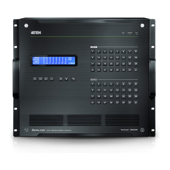
See Front Panel Pushbuttons, page 33, for details. Note: The pushbuttons have LEDs that light to indicate they have been selected. Input These pushbuttons refer to the Input ports on the VM3200 Pushbuttons rear panel. Press to select the Input port. These pushbuttons (1-32) may also correspond to menu options, profiles and other selections. - Page 25 Cable Strap A cable strap is provided to secure the power cord’s plug to the VM3200.
-
Page 26: Vm3200 Rear View
Serial Port this serial port. Ethernet Port In order to access the VM3200’s web Graphical User Interface (GUI), the VM3200 must be connected to the network. The cable that connects the VM3200 to your LAN plugs in here. See Cable Connection, page 30,... - Page 27 Modular Matrix Solution User Manual Component Description Grounding Terminal The grounding wire attaches here. See Grounding, page 27, for further details. Output Board slots Unscrew the cover to insert the output boards into these 8 vertical slots. The display devices connect to the inserted Output boards.
-
Page 28: Vm7404 Front View
Chapter 1. Introduction VM7404 Front View Component Description SDI Input Ports Connect the cables from your video source devices to these ports. Analog Stereo Audio Connect the cables from your audio source devices to these ports. Input Ports Status LED The VM7404 has an LED to indicate the working status. -
Page 29: Vm7514 Front View
Modular Matrix Solution User Manual VM7514 Front View Component Description HDBaseT Input Ports Connect the Cat 5e cables from your HDBaseT transmitter to these ports. IR / RS-232 Connect the cables from your IR transmitter to the mini stereo jack ports, and connect the cables from your Input Ports RS-232 device to the RS-232 ports. -
Page 30: Vm7804 Front View
Chapter 1. Introduction VM7804 Front View Component Description HDMI Input Ports Connect the cables from your HDMI video source devices to these ports. Audio Input Ports Connect the cables from your audio source devices to these ports. Status LED The VM7804 has an LED to indicate the working status. -
Page 31: Vm7604 Front View
Modular Matrix Solution User Manual VM7604 Front View Component Description DVI Input Ports Connect the cables from your video source devices to these ports. Audio Input Ports Connect the cables from your audio source devices to these ports. Status LED The VM7604 has an LED to indicate the working status. -
Page 32: Vm7104 Front View
Chapter 1. Introduction VM7104 Front View Component Description VGA Input Ports Connect the cables from your VGA video source devices to these ports. Audio Input Ports Connect the cables from your audio source devices to these ports. Status LED The VM7104 has an LED to indicate the working status. -
Page 33: Ve805R Front View
Modular Matrix Solution User Manual VE805R Front View VE805R Rear View Component Description LEDs Three LEDs – Power, Link and HDMI Out – light when the unit is properly connected to an appropriate source. Power - lights Green to indicate the unit is receiving power. - Page 34 Chapter 1. Introduction Component Description Firmware Upgrade Set this switch to OFF (left) for normal operation. Set Switch this switch to ON (right) and reset the unit’s power to enter firmware upgrade mode (see page 108 for details). HDBaseT Input Use a Cat 5e cable to connect the VE805R to the VM8514 output board.
- Page 35 Modular Matrix Solution User Manual This Page Intentionally Left Blank...
-
Page 36: Hardware Setup
Placement When not rack mounted, the VM3200 should be placed on a flat and level surface with the bottom side down. The unit should never be placed with the front, rear or sides facing the ground. -
Page 37: Rack Mounting
2. Use screws to attach the unit to the rack. Note: 1. Please allow 1U (44 mm) of space between the top of the VM3200 and any object to prevent obstruct of the air flow. - Page 38 Chapter 2. Hardware Setup Mounting with Brackets You can also use mounting brackets to install the VM3200, as shown below. Note: The Easy Installation Mounting Kit is not included with the package (see page 10). To purchase a mounting kit please contact your dealer.
- Page 39 Modular Matrix Solution User Manual 3. Screw the front panel to the rack. Note: 1. Please allow 1U (44 mm) of space between the top of the VM3200 and any object to prevent obstruct of the air flow. 2. To ensure the VM3200 has sufficient air flow, do not stack items on top or in front of the unit.
-
Page 40: Grounding
To prevent damage to your installation, it is important that all devices are properly grounded. 1. Use a grounding wire to ground the installation using the VM3200’s rear panel, by connecting one end of the wire to the grounding terminal, and the other end of the wire to a suitable grounded object. -
Page 41: Input / Output Board Installation
The eight left slots on the Modular Matrix Switch are for the Output boards. 1. On the rear of the VM3200, remove two screws from a left and right side slot, and then remove both covers. (Continues on next page.) - Page 42 Chapter 2. Hardware Setup 2. Slide an output board into a left side slot and then tighten the two screws to secure the board to the VM3200. 3. Slide an input board into a right side slot and then tighten the screws to secure the board to the VM3200.
-
Page 43: Cable Connection
Note: Do not omit this step. Proper grounding helps to prevent damage to the unit from surges or static electricity. 2. Unscrew the covers on the VM3200’s rear panel and insert the I/O boards into the vertical slots (See Input / Output Board Installation, page 28, for details). -
Page 44: Installation Diagram
Chapter 2. Hardware Setup 11. Power on the VM3200 and all devices in the installation. Installation Diagram... - Page 45 Modular Matrix Solution User Manual This Page Intentionally Left Blank...
-
Page 46: Front Panel Operation
The VM3200 front panel has easy-to-use pushbuttons for selecting which video/audio source shows on which display. Basic Navigation The VM3200’s front panel LCD display operation is easy and convenient. Please note the following front panel button operations: Press the VIDEO pushbutton to configure the video connections. -
Page 47: Front Panel Lcd
Enter a 4-digit password to continue to the Main Screen. Note: If you are accessing the VM3200 for the first time, the default password is 1234. Enter Password: * * * *... - Page 48 Chapter 3. Front Panel Operation displays at the bottom of the screen, but clears as soon as a new digit is entered. 3. If Password (see Security Mode, page 52) is Enabled, the LCD display time-out is 5 minutes by default.
-
Page 49: Port Switching
Modular Matrix Solution User Manual Port Switching From the Main Screen, you can configure the Input-to-Output port connections to associate an Input source device to an Output display. Video / Audio Pushbutton Before switching port connections, use the Video or Audio pushbuttons to select whether to switch only the video or the audio signal exclusively. -
Page 50: Input Port Selection
Chapter 3. Front Panel Operation Input Port Selection Use the Input Port pushbuttons to select the Input port you want to configure. INPUT V + A OUTPUT INPUT ↓ :Next OUTPUT 9 10 11 12 13 14 15 16 To select which input source displays on each output port, do the following: 1. - Page 51 Modular Matrix Solution User Manual 3. To switch to another Input port, press any Input port pushbutton. The Output port LED(s) tied to the said Input port will flash. In the example below, pressing Input port 2 shows it is tied to Output ports 3 and 4.
-
Page 52: Output Port Selection
Chapter 3. Front Panel Operation Output Port Selection Use the Output Port pushbuttons to select the Output port you want to configure. INPUT V + A OUTPUT INPUT ↓ :Next 9 10 11 12 13 14 15 16 OUTPUT To select which output display corresponds to each input source, do the following: 1. - Page 53 Modular Matrix Solution User Manual 4. To switch Output ports 2, 3 and 4 to another Input port (and disconnect it from Input port 2), press another Input port pushbutton to which you want them tied. In the example below, Input port 3 has been pressed and is now connected to Output ports 2, 3 and 4.
-
Page 54: Profile Pushbutton
Note: If a Profile is available for selection, its corresponding Input/Output port LED lights. The selected pushbutton lights steady, and the VM3200 immediately applies the port connections configured in the Profile. The selected Profile is shown as P1-P64 in the LCD’s lower right corner. -
Page 55: Lcd Menu
Turn Video Wall Off Note: 1. The highlighted values are the default settings of the VM3200. 2. Upon VM3200 startup, check the front panel LCD to view the loading progress. If the LCD Menu fails to load, an error message displays. -
Page 56: Lcd Main Screen
Chapter 3. Front Panel Operation LCD Main Screen The Main Screen shows the Input–Output port pairs, with the Output ports shown in sequential order (1–16) at the bottom half. V + A INPUT OUTPUT INPUT ↓: Next OUTPUT 9 10 11 12 13 14 15 16 ... -
Page 57: Ip Setting
Modular Matrix Solution User Manual IP Setting To view the VM3200’s IP settings, press the Menu pushbutton (lights). This takes you to the Menu page, shown below: 1: IP Se ng 2: Serial Port Se ng 3: Opera on Mode ↓: Next... -
Page 58: Serial Port Setting
Chapter 3. Front Panel Operation Serial Port Setting To configure the VM3200’s serial port settings, select Serial Port Setting from the Menu page. 1: IP Se ng 2: Serial Port Se ng 3: Opera on Mode ↓: Next 4: Security Mode Baud Rate 1. -
Page 59: Operation Mode
Modular Matrix Solution User Manual Operation Mode The EDID, CEC, OSD and Output Status features are adjusted from the Operation Mode menu. 1: EDID Mode: Default 2: CEC 3: OSD ↓: Next 4: Output Status EDID (extended display identification data) is used to apply a preset video configuration (EDID Mode), which utilizes the best resolution across different monitors. - Page 60 EDID Mode options are: EDID Option Description 1: Default ATEN’s default EDID data is passed to all video sources by default when the system is powered on. 2: Port1 EDID data read from port 1 is passed to all video sources.
-
Page 61: Cec
Modular Matrix Solution User Manual To configure the CEC settings, do the following: 1. From the Operation page, press pushbutton 2 to access the CEC page: 1: EDID Mode: Default 2: CEC 3: OSD ↓: Next 4: Output Status 2. Press pushbuttons 1–32 to enable (ON) or disable (NA) the CEC feature for the output port. -
Page 62: Osd
The On-Screen Display or OSD feature enables real-time text updates to appear on the display device’s screen for any configuration changes made to the Output port via the VM3200’s front panel, remote control or Web GUI. To configure the OSD setting for each output port, do the following: 1. -
Page 63: Output Status
Modular Matrix Solution User Manual Output Status To configure the Output Status settings for each output port, do the following: 1. From the Operation Mode screen, press pushbutton 4 to access the Output Status page: 1: EDID Mode: Default 2: CEC 3: OSD ↓: Next 4: Output Status... - Page 64 Chapter 3. Front Panel Operation 5. If configuring the output video resolution, press pushbuttons 1–32 to select the output port. Next, select the preferred output resolution. 6. Press Menu to return to the Menu page. 7. Press Cancel to return to the previous step without saving.
-
Page 65: Security Mode
Security Mode page. 1: Mode 2: Change Password Mode 1. To set the VM3200 so that it requires a password for local operation, press pushbutton 1 in the Security Mode page. 1: Mode 2: Change Password 2. To disable security settings, press pushbutton 1. -
Page 66: Change Password
(1111–9999). Old Password : * * * * New Password: * * * * 4. Re-enter the new password in the following screen. The new password is applied by the VM3200 immediately. - Page 67 Modular Matrix Solution User Manual Old Password : * * * * New Password: * * * * Re-enter New Password: * * * * If the password you entered does not match the one entered in the previous screen, an error message appears. Enter the new password correctly. 5.
-
Page 68: Save To A Profile
Chapter 3. Front Panel Operation Save to a Profile The VM3200 allows you to store up to 64 (P1–P64) different connection profiles that can be saved and recalled later. When profiles are saved, they are saved according to the current connection configuration on the Main Screen. -
Page 69: Play/Stop The Profile Schedule
Modular Matrix Solution User Manual Play/Stop the Profile Schedule Inputting port pushbutton 2 will Play or Stop the active Profile Schedule. :Prev 1: Save to a profile 2: Play/stop the profile schedule 3: Turn video wall off Turn Video Wall Off If a video wall is currently playing, a submenu will appear. -
Page 70: Browser Operation
Logging In To access the GUI, type the VM3200’s IP address into the address bar of any browser. If a Security Alert dialog box appears, accept the certificate – it can be trusted. The login screen appears: ... -
Page 71: Main Page
Modular Matrix Solution User Manual Main Page The Main Page opens to the Profile List. This is where you configure the input to output connections by creating profiles. The page is divided into three parts: the Menu Bar, Profile List, and Profile Scheduling. Menu Bar The Menu Bar consists of the Settings icon and Logout button. -
Page 72: Profile List
Chapter 4. Browser Operation Profile List The Profile List lets you configure the input to output port connections by creating profiles to use. You can store up to 64 differently configured profiles that can be saved and played later by two methods: locally via the unit’s front panel pushbuttons and via the web GUI. - Page 73 Modular Matrix Solution User Manual (Continues on next page.) 4. Select the profile and click Apply. 5. The profile appears in the large Play window and the connections start: Note: More information about the Profile List is provided on the next page.
-
Page 74: Importing/Exporting A Profile
To export the VM3200’s connection profiles, do the following: 1. Click Export Profiles. A configuration file will then begin downloading. To import connection profiles to the VM3200, do the following: 1. Click Import Profiles. 2. Browse to the configuration file, select it and click Open. -
Page 75: Profile List Options
Modular Matrix Solution User Manual Profile List Options Clicking on a Profile or the Play window opens a pop-up menu with options. Profile Option Description Apply Click Apply to put the profile in the Play window. This allows you to start the profile connections. -
Page 76: Play Window
Chapter 4. Browser Operation Play Window Option Description Show OSD Check Show OSD to show the current connection status via OSD. When Show OSD is unchecked, the OSD will disappear. Mute All Check Mute All to mute the audio for all ports. Blank All Check Blank All to turn off the video to all displays. -
Page 77: Change Input
Modular Matrix Solution User Manual Change Input The Change Input page gives you a preview of what’s displayed on all screens, allows you to change the inputs and view a live stream of each input. To access this page, click Change Input from the Play Window (see Play Window, page 63). -
Page 78: Live Streaming View
Chapter 4. Browser Operation Live Streaming View This window gives you a live stream of the video source. To access this page click an input from the right column on the Change Input page (see Change Input, page 64). Option Description Click the icon to increase / decrease the size of the live preview window. -
Page 79: Profile Scheduling
Modular Matrix Solution User Manual Profile Scheduling Profile Scheduling is located below the Profile List. Scheduling allows you to queue and play connection profiles via a calender view for a specific amount of time. Adding Profiles Select All Playlist on the Profile Scheduling page then click Add Playlist, a window opens to add profiles. -
Page 80: All Playlist
Chapter 4. Browser Operation All Playlist Manage all playlists on the Profile Scheduling by selecting All Playlist. A new window opens; the options are: Name, Sequence, Start Time, End Time, Frequence. -
Page 81: Editing Profile Scheduling
Modular Matrix Solution User Manual Editing Profile Scheduling After adding profiles to Profile Scheduling, the following options are available: Option Description Click to add a profile to the schedule. The schedule plays profiles in order from left to right. Use the options under each profile to configure the duration of each profile being played (see below). -
Page 82: Playing Profile Scheduling
Chapter 4. Browser Operation Option Description Save Click Save to save the schedule as it appears. After saving, the Profile Scheduling window stays open allowing you to Play or Edit the schedule. When a Profile Schedule is playing the On Sequence box will appear in the Play window. - Page 83 Modular Matrix Solution User Manual Option Description Click open to view All Playlists Click on the Today button to go to current week period. Click the previous week or next week icons, to scroll through the calendar Select a month to view from the drop down menu Select a week to view from the drop down menu...
-
Page 84: Connection Profiles
Chapter 4. Browser Operation Connection Profiles Connection profiles configure the source to display connections. You can create up to 64 connection profiles that can be selected for use at any time. The configuration page opens after you click to add or edit a profile from the Profile List (see Profile List, page 59). -
Page 85: Side Panel
Modular Matrix Solution User Manual Side Panel The Side Panel sets up the layout type for the Video Wall(see Layout Type, page 71). When you Apply changes in the Side Panel, the Main Page layout changes to match that of the settings. Option Description Number of... - Page 86 Chapter 4. Browser Operation Option Description Monitor Click the monitor icon to Lock the (4) bezel settings, so that when one size is changed they all change. Lock / Unlock Click the monitor icon to Unlock the (4) bezel settings, so that each size can be set independently.
-
Page 87: Main Page
Modular Matrix Solution User Manual Main Page The Main Page has Output icons that represent the physical displays. Each icon allows you to configure a displays input port, output port and other options. The number and arrangement of Output icons depends on the Side Panel settings (see Side Panel, page 72). -
Page 88: Output Icon
Chapter 4. Browser Operation Output Icon Option Description Output Icon Click an Output icon(s) to highlight it in green and use the Display Preferences menu to set the video and audio input options (see Display Preferences below). The large number is the Video Input port selected for the display. The drop-down menu in the upper-left corner is used to select the Output port of the display. -
Page 89: Display Preferences
Modular Matrix Solution User Manual Display Preferences Option Description Display The Display Preferences menu appears when you click an Output Preferences icon. Output Use the drop-down menu to select the Output Input port. Video Input Use the drop-down menu to select the Video Input port. Audio Input Use the drop-down menu to select the Audio Input port. -
Page 90: Grid View
Chapter 4. Browser Operation Grid View The Traditional View allows you to select the Input to Output and Audio connections using a simple grid. Select: Video & Audio, Video, or Audio to set the input to output connection for the selected source. ... -
Page 91: Video Wall
Modular Matrix Solution User Manual Video Wall Each icon represents an Output port and the connected display. Use the icons to create Independent and Grouped Outputs. Independent Outputs will display video on a single monitor. Grouped Outputs will display video across multiple monitors as one large screen. -
Page 92: Null Input
Chapter 4. Browser Operation Null Input Option Description Null Icon Click Null Input icons to highlight icons in green and use the Display Preferences menu to set the video options (see Display Preferences, page 81). Select a single icon to set the Output and Video Input for an independent display (see Independent Output, page 79). -
Page 93: Grouping
Modular Matrix Solution User Manual Grouping Option Description Grouping Click multiple icons to Group Outputs (highlighted in green) and click to group the displays into one screen. Use the Display Preferences menu to select the Video Input for the group - each Output icon in the Group will appear with the same Video Input number and icon color. -
Page 94: Display Preferences
Chapter 4. Browser Operation Display Preferences Option Description Display Click Output icons for the Display Preferences menu to appear– to Preferences select the Output, Video Input and Audio Input ports. Output Use the drop-down menu to select the Output port (Independent and single Blank icons only). - Page 95 Modular Matrix Solution User Manual Video Wall Example 1 This example shows a video wall with 8 displays. This video wall has 1 Group and 4 Independent displays. Each Group and Independent Output has a unique color. The Blue Group will show video Input 02 across all four displays as one large screen.
- Page 96 Chapter 4. Browser Operation Video Wall Example 2 This example shows a video wall with 16 displays. This video wall has 3 Groups and 2 Independent displays. Each Group and Independent Output has a unique color. The Blue Group will show video Input 02 across six displays as one large screen.
-
Page 97: Output Options
Modular Matrix Solution User Manual Output Options The Output Options page is used to configure Audio Controls and Video Control. Audio Control HDMI / Stereo Control: Use the drop-down menu to apply audio setting to all ports: All Ports Use HDMI Audio. ... - Page 98 Chapter 4. Browser Operation Click Save as to save the profile as a different profile number. Click Cancel to undo all unsaved changes.
-
Page 99: Video Control
Modular Matrix Solution User Manual Video Control Video Control allows you to set Seamless Switch options which determine how a display performs when the input port is changed. The Transition, Period and Scale Resolution options are disabled when Seamless Switching is turned off. The Seamless Switch function cannot be turned off from the video wall editor. - Page 100 Chapter 4. Browser Operation Click Save & Apply to save a profile and begin playing it. Click Save to save the profile. Click Save as to save the profile as a different profile number. Click Cancel to undo all unsaved changes.
-
Page 101: System Settings
The OSD/CEC page allows users to control port OSD and CEC > settings. Use to access the OSD/CEC page. Click Profile List to return to the Main page. Note: The IR/RS232 Channel page is only available when VM7514/VM8514 I/O boards are installed in the VM3200. -
Page 102: General
RS232 Control Mode allows the user to control the (remote) devices that are connected to VM3200 through its RS232 channels. Select the RS232 Control Mode and click save. On the RS232 Channel tab, you'll be able to choose from two modes: Broadcast (1-All) or Manual... -
Page 103: Fan Status
Power Status This section displays the status of the Primary and Redundant Power units. Device Info This section lists information about input and output boards connected to the VM3200, such as Model Name, Firmware Version, Temperature and Power Consumption. -
Page 104: System Time
Chapter 4. Browser Operation System Time System Time allows the time to be set in accordance with the needs of the profile scheduling. Click on Edit; a new window will appear. -
Page 105: Other
Modular Matrix Solution User Manual The Time Setting edit window has different configuration options. The options are: Synchronize with Computer Time - Select to duplicate the time the computer. Synchronize with Server Time - Select to duplicate the time of a server. You can choose the server from the drop down menu, or manually enter a server’s IP address. -
Page 106: User Account
VM3200’s GUI. Note: This is an Administrator only function. + Add account – Click to add a new user account. The VM3200 supports up to 32 users (see Add Account, page 94). Edit – Click to change a user’s information. This option allows an Administrator to edit accounts. -
Page 107: Add Account
Click Create User to save the data. Click Cancel to discard the changes and exit. If a user is logged into the VM3200’s GUI, their user settings cannot be edited, and the fields in this screen are grayed out. -
Page 108: Permission Level
The three available permission levels are as follows: Administrator – this level provides full access and control of the VM3200, in addition to full User Management privileges. Advanced User – this level provides full access and control with no User Management privileges. -
Page 109: Port Name
Modular Matrix Solution User Manual Port Name The Port Name page lets users name the Input and Output ports for easy identification. To name an Input/Output port, enter a descriptive name of up to 16 characters (including 0-9, a-z, A-Z, _, -) in the corresponding field. ... -
Page 110: Network
GUI, and enable/disable Telnet. Enable DHCP to allow the DHCP server to assign an IP address to the VM3200. Select Disable to enter your own static IP address settings for the device. Click Reset to use the following default values: ... -
Page 111: Edid
Modular Matrix Solution User Manual EDID The EDID page lets users view and select an EDID Mode so that the VM3200 can use the best resolution for its display(s). Note: The EDID Mode can also be selected via the Front Panel pushbuttons –... -
Page 112: Edid Mode
In the left panel of the page, users can select a pre-configured EDID Mode using the EDID Mode radio buttons. Select the EDID Mode to use and click Apply. The VM3200 uses the settings configured for that EDID mode. Options are: ... -
Page 113: Edid & Cea Description
Modular Matrix Solution User Manual EDID & CEA Description The right panel of the screen lets users view the configuration of the EDID and CEA Modes selected: From the left column, click the option that you want to view and/or edit. -
Page 114: Customize Mode
Retrieve EDID: Click and a pop-up window appears to retrieve the EDID settings of a stored EDID configuration: Customized EDID 01- 32, Display Port or ATEN Default. Select the port to retrieve: The right panel displays a summary of the acquired EDID settings that you can edit. -
Page 115: Customized Edid Parameters
Modular Matrix Solution User Manual Customized EDID Parameters The EDID structure is comprised of 128 bytes in total – each heading shown in the left column corresponds to a specific number of bytes. The pages for the pre-configured EDID Modes (Port 1, Default and Remix) cannot be edited. - Page 116 Chapter 4. Browser Operation Standard Timings This page shows eight resolutions/timings that display devices can support in addition to those listed in the Established Timings page. Select the H Active Pixel from the drop-down menu. Select the Aspect Ratio from the drop-down menu. ...
- Page 117 Modular Matrix Solution User Manual Monitor Description This screen lets you specify the viewing specifications, namely horizontal and vertical scan ranges and pixel clock rate, of your monitor/display device. Enter the values that correspond to your device and click Save to apply the changes.
-
Page 118: Cea Settings
Chapter 4. Browser Operation CEA Settings CEA is an extension data of the EDID structure, which further extends the standard definitions of EDID to support advanced features of monitors/display devices. Display Support This screen describes the display’s basic digital components. Select the YCbCr mode applicable to your display and click Save. -
Page 119: Video Data
Modular Matrix Solution User Manual Video Data This screen lists additional video resolution/timing displays that may be supported by other devices, other than PC monitors (for example, 1080i). Select the native resolution of the attached display device. Select the resolutions that work with the attached monitor/display device. -
Page 120: Audio Data
Chapter 4. Browser Operation Audio Data This screen lets you select advanced audio configurations for your device. Use the drop down menu to select the Audio Format (1~6) applicable to your audio output device, and click Save to apply the changes. Detail Timing / Display Description This screen gives more video resolution options, and provides resolution/ timing details (in addition to those specified in the EDID structure). -
Page 121: Maintenance
Modular Matrix Solution User Manual Maintenance The Maintenance page lets users upgrade the VM3200’s firmware and back up or restore system settings. This is an Administrator only function. To upgrade the VM3200’s firmware, do the following: 1. Use the Browse button to locate the firmware upgrade file. Make sure you have the correct file saved on your PC. - Page 122 Chapter 4. Browser Operation 3. Power on the VE805R and turn its Firmware Upgrade switch to ON. 4. Reset the VE805R's power to enter firmware upgrade mode. The HDMI Out LED blinks orange every second to indicate the device is in F/W upgrade mode.
-
Page 123: Ir/Rs232 Channel
Modular Matrix Solution User Manual IR/RS232 Channel The RS232 Channel page is available for VM7514 and VM8514 boards only. The options allow you to set ports to use RS232 which will direct the board to use the local RS232 port signals, or HDBaseT RS232 which will direct the board to use the HDBaseT port for the RS232 signals for control. - Page 124 Chapter 4. Browser Operation In-Board: Set each input port to use the Local IR/RS232, HDBaseT IR/ RS232, or Loopback setting for the IR/RS232 signals. Use the drop-down menu to apply an option to all ports; or select Local IR/RS232, HDBaseT IR/RS232 or Loopback for individual ports.
-
Page 125: Hdcp
Modular Matrix Solution User Manual HDCP The HDCP page lets users view and set HDCP key settings between input and output ports for digital copy protection and to ensure Seamless Switching between different devices. This is an Administrator and Advanced User only function. -
Page 126: Osd/Cec
Chapter 4. Browser Operation OSD/CEC The OSD/CEC page lets users view and set OSD and CEC settings for all ports. OSD: Sets the default OSD option for the port. When OSD is on, real- time text updates appear on the display for 10 seconds when configuration and port changes are made to its output. -
Page 127: Telnet Operation
The VM3200 can be operated and configured via a remote terminal session using Telnet. To log into the VM3200 by means of a Telnet session, do the following: 1. On your computer, open a terminal (command line) session. 2. At the prompt, key in the VM3200’s IP address in the following way: telnet [IP address]:23 3. -
Page 128: Ip - Set Ip Address
Chapter 4. Browser Operation 2. IP – Set IP address Old IP address: 192.168.0.60 New IP address: 3. LO – Load connections from profile LO 01 Load profile 01 OK. 4. PW – Change password Old password: ******** New password: 5. -
Page 129: 10. Ti - Set Timeout
Modular Matrix Solution User Manual Save the current connections into profile 01 10. TI – Set timeout TI 30 Set 30 minute timeout 11. VR – Software version information Software version 1.0. Note: All RS-232 commands in this manual are also applicable in Telnet mode, see page 119 for details Note: For further information about these functions, please reference the... -
Page 130: Rs-232 Commands
Chapter 5 RS-232 Commands Serial Control Protocol Commands The VM3200’s built-in bi-directional RS-232 serial interface allows system control through a high-end controller or PC. RS232 Pin Assignment Description Description Not connected Not connected Not connected Not connected Not connected Not connected Configuring the Serial Port The controller’s serial port should be configured as follows:... -
Page 131: Verification
Modular Matrix Solution User Manual RS-422 / RS-485 In the sections that follow the formulas that include an “address” command are for RS-422 and RS-485 serial port devices when the VM3200 is setup in cascade installation. Verification After entering a command, a verification message appears at the end of the command line as follows: ... -
Page 132: Switch Port Command
Chapter 5. RS-232 Commands Switch Port Command The formula for Switch commands is as follows: Switch Command + Input + Num1 + Output + Num2 + Address + Num3 + Stream + Control [Enter] 1. For example, to switch input port 02 to output port 05, type the following: sw i02 o05 [Enter] 2. - Page 133 Modular Matrix Solution User Manual Num3 Description Device address zz: 01~16 (default is 01) (RS-422 and RS-485 only) All devices Stream Description video Switch Video channel only audio Switch Stereo Audio channel only Switch Video channel and Stereo Audio channel default select if been omitted Control Description...
- Page 134 Chapter 5. RS-232 Commands The following table shows the available command list: Devi Com- Input Output Addr Description Input Output Stream Control Enter mand Port Port video Switch Input Port xx [Enter] to Output Port yy on audio Address zz xx:01~16, * yy:01~16, * zz: 01~16, *...
-
Page 135: Mute Command
Modular Matrix Solution User Manual Mute Command Mute allows you to enable or disable an output port(s) audio. The Mute command will turn on/off the HDMI audio and stereo audio. When the HDMI audio is off, the stereo's volume can be adjusted using the volume command. The formula for the Mute command is as follows: Command + Output + Num1 + Address + Num2 + Control + [Enter] 1. - Page 136 Chapter 5. RS-232 Commands Control Description Mute off; audio on output port is enabled (default) Note: 1. Each command string can be separated with a space. 2. The Address command is for RS-422/485 only. If the address parameter is missing from RS-422/485 commands, the default a00 will be used.
-
Page 137: Volume Command
Modular Matrix Solution User Manual Volume Command The volume command allows adjusts the stereo volume for an output port. The formula for the Volume command is as follows: Command + Output + Num1 + Address + Num2 + Volume + Control + [Enter] 1. - Page 138 Chapter 5. RS-232 Commands Control Description Audio volume level zz: 01~10 (default is 10) Note: 1. Each command string can be separated with a space. 2. The Address command is for RS-422/485 only. If the address parameter is missing from RS-422/485 commands, the default a00 will be used.
-
Page 139: Save/Load Profile Commands
Modular Matrix Solution User Manual Save/Load Profile Commands The Save/Load Profile command allows you to save the current connection configuration as a profile and load connection profiles. The formula for Save/Load Profile commands is as follows: Command + Profile + Num1 + Address + Num2 + Control + [Enter] 1. - Page 140 Chapter 5. RS-232 Commands Control Description load Load a saved profile Note: 1. Each command string can be separated with a space. 2. The Address command is for RS-422/485 only. If the address parameter is missing from RS-422/485 commands, the default a00 will be used.
-
Page 141: Edid Mode Command
Port 1, and pass it to the video source. remix Implement the EDID of each connected display according to its connection when the VM3200 is first powered on, or immediately after selecting the Remix option. default Implements ATEN’s default EDID. - Page 142 [Enter] The EDID from Port 1 is passed to the video source. zz: 01~16 edid remix [Enter] The VM3200 implements the EDID of each connected display according to its connection when the device is first powered on, or immediately after selecting the Remix option.
-
Page 143: Cec Command
Modular Matrix Solution User Manual CEC Command Consumer Electronics Control (CEC) allows interconnected HDMI devices to communicate and respond to the same remote control. The formula for the CEC command is as follows: Command + Output + Number + Control + [Enter] 1. -
Page 144: Read Command
Chapter 5. RS-232 Commands Read Command The Read command allows you to view information about the devices. The formula for the Read command is as follows: Command + Address + Number + [Enter] 1. To view information, type: read [Enter] 1. - Page 145 Modular Matrix Solution User Manual How to read the commands: 1. o01 i03 video on i06 audio v10 HDMI-a on 1080p Output 01 is connected to Input 03 with video on; audio is on from Input 06 with volume 10 using the HDMI audio source; the resolution is scaled to 1080p 2.
-
Page 146: Reset Command
Chapter 5. RS-232 Commands Reset Command The Reset command allows you to reset the VM3200 back to the default factory settings. Reset includes resetting the devices IP address. The formula for the Reset command is as follows: Command + Address + Number + [Enter] 1. -
Page 147: Baud Rate Command
Baud Rate Command The Baud Rate command allows you to set the RS-232 data rate for the VM3200 to use. Options are 9600, 19200 (default) 38400 and 115200. The formula for the Baud Rate command is as follows: Command + Control + [Enter] 1. -
Page 148: Osd Command
Chapter 5. RS-232 Commands OSD Command To enable or disable the On-Screen Display (OSD) for displays, use the following command: Command + Output + Number + Control + [Enter] 1. For example, to enable the OSD for output 07, type: osd o07 on [Enter] 2. -
Page 149: Echo Command
Modular Matrix Solution User Manual Echo Command The Echo function updates the RS232 controller when operations are made via the front panel pushbuttons, web browser or telnet. The changes echo back to the RS232 controller to keep the settings in sync with the device. The formula for the Echo command is as follows: Command + Control + [Enter] 1. -
Page 150: Scaling Command
Chapter 5. RS-232 Commands Scaling Command The Scaling command allows you to set a resolution for scaling the display connected to an output port. The formula for the Scaling command is as follows: Command + Output + Number 1 + Address + Number 2 + Horizontal Resolution + Number 3+ Vertical Resolution + Number 4 + Frequency + Number 5 + Control + [Enter] 1. - Page 151 Modular Matrix Solution User Manual Horizontal Description Resolution Horizontal resolution command for scaling Resolution Number Description hhhh Horizontal resolution Vertical Resolution Description Vertical resolution command for scaling Resolution Number Description vvvv Vertical resolution Frequency Description freq Frequency command for scaling Frequency Number Description Frequency resolution...
- Page 152 Chapter 5. RS-232 Commands 3. The Port Number command string can be skipped, and the default value will be used. The following table lists the available Scaling commands: Hori Verti Freq zont Description scaling freq Turn off ter] scaling for output yy device zz (by pass...
- Page 153 Modular Matrix Solution User Manual Hori Verti Freq zont Description scaling hor 12 freq Scale ter] output yy device zz 1280x720 @60Hz yy: 01~16 or * zz: 01~16 or * scaling hor 19 1200 freq Scale ter] output port yy device zz to 1920x120 0@60Hz...
- Page 154 Chapter 5. RS-232 Commands Hori Verti Freq zont Description scaling hor 12 1024 freq Scale ter] output yy device zz 1280x102 4@60Hz yy: 01~16 or * zz: 01~16 or * scaling hor 10 freq Scale ter] output yy device zz 1024x768 @60Hz yy: 01~16...
-
Page 155: Fan Speed Command
Modular Matrix Solution User Manual Fan Speed Command The Fan Speed command allows you to set the VM3200’s internal fan speed. To set the fan speed, use the following command: Command + Control + [Enter] 1. For example, to set the fan to auto detect, type:... -
Page 156: Alert Command
Chapter 5. RS-232 Commands Alert Command To trigger a warning when issues arise for a specific input port, use the following command: Command + Input + Number + Control + [Enter] 1. For example, to enable the basic Alert function for input port 1, type: alert i01 m1 [enter] The following tables show the possible values for the Alert command: Command... - Page 157 Modular Matrix Solution User Manual This Page Intentionally Left Blank...
-
Page 158: Appendix
Appendix Safety Instructions General Read all of these instructions. Save them for future reference. Follow all warnings and instructions marked on the device. This product is for indoor use only. Do not place the device on any unstable surface (cart, stand, table, etc.). If the device falls, serious damage will result. - Page 159 Modular Matrix Solution User Manual If an extension cord is used with this device make sure that the total of the ampere ratings of all products used on this cord does not exceed the extension cord ampere rating. Make sure that the total of all products plugged into the wall outlet does not exceed 15 amperes.
-
Page 160: Rack Mounting
Appendix Rack Mounting Before working on the rack, make sure that the stabilizers are secured to the rack, extended to the floor, and that the full weight of the rack rests on the floor. Install front and side stabilizers on a single rack or front stabilizers for joined multiple racks before working on the rack. -
Page 161: Technical Support
Modular Matrix Solution User Manual Technical Support International For online technical support – including troubleshooting, documentation, and software updates: http://eservice.aten.com For telephone support, see Telephone Support, page iv: North America Email Support support@aten-usa.com Online Troubleshooting http://www.aten-usa.com/support Technical Documentation... -
Page 162: Specifications
Appendix Specifications VM3200 Function VM3200 Board Input 8 x Slot Board Output 8 x Slot Video Input Interface Depends on which I/O board is inserted Impedance 100 Ώ Maximum Data Rate 10.2 Gbps (3.4 Gbps per lane) Maximum Pixel Clock... - Page 163 Modular Matrix Solution User Manual Function VM3200 Physical Housing Metal Properties Weight 18.20 kg (chassis only) Dimensions (L x W x H) 48.20 x 47.19 x 39.90 cm...
-
Page 164: Vm7404
Appendix VM7404 Function VM7404 Video Input Interface 4 x BNC Female Impedance 75 Ώ Maximum Bandwidth 300 MHz Maximum Data Rate 2.97 GHz Maximum Resolution 1920 x 1080 Maximum Distance 90 m (3G-SDI); 140 m (HD-SDI); 300 m (SD-SDI) Audio Interfaces 4 x Captive Screw Connectors, 5 pole Audio signal type*: stereo, balanced /... -
Page 165: Vm7514 / Vm8514
Modular Matrix Solution User Manual VM7514 / VM8514 Function VM7514 VM8514 Connectors HDBaseT In 4 x RJ-45 Female (Silver) HDBaseT Out 4 x RJ-45 Female (Silver) 4 x Mini Stereo Jack 4 x Mini Stereo Jack Female (Black) Female (Black) RS-232 4 x Captive Screw 4 x captive screw... -
Page 166: Vm7804 / Vm8804
Appendix VM7804 / VM8804 Function VM7804 VM8804 Connectors HDMI In 4 x HDMI Female (Black) HDMI Out 4 x HDMI Female (Black) Stereo Audio In 4 x captive screw connector, 5 pole Stereo Audio Out 4 x captive screw connector, 5 pole Status 1 (Green) 1 (Green) -
Page 167: Vm7604 / Vm8604
Modular Matrix Solution User Manual VM7604 / VM8604 Function VM7604 VM8604 Connectors DVI In 4 x DVI-D Female (White) DVI Out 4 x DVI-D Female (White) Stereo Audio In 4 x captive screw connector, 5 pole Stereo Audio Out 4 x captive screw connector, 5 pole Status 1 (Green) -
Page 168: Vm7104
Appendix VM7104 Function VM7104 Connectors VGA In 4 x HDB-15 Female (Blue) Stereo Audio In 4 x captive screw connector, 5 pole Status 1 (Green) Power Consumption 7.1 W Environment Operating Temp. 0–40ºC Storage Temp. -20–60ºC Humidity 0–80% RH, Non-condensing Physical Housing Metal... -
Page 169: Ve805R
Modular Matrix Solution User Manual VE805R Function VE805R Connectors HDMI Out 1 x HDMI Type A Female (Black) HDBaseT In 1 x RJ-45 Female (Silver) RS-232 1 x captive screw connector, 3 pole 1 x 3.5mm Phone Jack (Black) Power 1 x DC Jack (Black) Power 1 (Green) -
Page 170: Vm-Pwr800
Appendix VM-PWR800 Function VM-PWR800 Properties Input Voltage 100~240Vac Max.Load 800W Power Consumption Operating Temp. 0–40ºC VM-FAN556 Function VM-FAN556 55.2 cfm Properties Air Flow Operating 10.8-13.8 Vdc Voltage Operating Temp. -10–70ºC Limited Warranty IN NO EVENT SHALL THE DIRECT VENDOR'S LIABILITY EXCEED THE PRICE PAID FOR THE PRODUCT FROM DIRECT, INDIRECT, SPECIAL, INCIDENTAL, OR CONSEQUENTIAL DAMAGES RESULTING FROM THE USE OF THE PRODUCT, DISK, OR ITS DOCUMENTATION. - Page 171 Modular Matrix Solution User Manual This Page Intentionally Left Blank...
Need help?
Do you have a question about the VM3200 and is the answer not in the manual?
Questions and answers