
Related Manuals for Emerson Unidrive M101


Summary of Contents for Emerson Unidrive M101
- Page 1 Quick Start Guide Unidrive M100-101 Frame sizes 1 to 4 Value drive with quality and performance for open loop applications Part Number: 0478-0035-06 Issue: 6...
- Page 2 This guide is intended to provide basic information required in order to set-up a drive to run a motor. For more detailed installation information, please refer to the Unidrive M100 / 101 User Guide which is available to download from: http://www.emersonindustrial.com/en-EN/controltechniques/downloads/userguidesandsoftware/ Pages/downloads.aspx.
-
Page 3: Table Of Contents
Contents Product information ..................5 Ratings ........................5 Options ......................6 Mechanical installation ................6 Electrical installation ...................9 AC supply requirements ..................9 External braking resistor ..................9 Ground leakage ..................... 11 Control terminal configurations and wiring ............. 12 EMC ........................17 Keypad and display ...................19 Saving parameters .................... - Page 4 Declaration of Conformity Control Techniques Ltd Moteurs Leroy-Somer The Gro Usine des Agriers Newtown Boulevard Marcellin Leroy Powys CS10015 16915 Angoulême Cedex 9 SY16 3BE France This declaration applies to the Unidrive-M product range comprising model numbers listed below: Model Interpretation Format: Xaaa-bbc ddddde Format: Xaa-bbc ddddde...
-
Page 5: Product Information
Product information Ratings Nominal cable size Max input Output current fuse rating Max. European Input cont Max. phases input cont Nominal Motor Model 1 Ph 3 Ph Input Output Input Output current output power power current 01100017 0.25 0.33 01100024 11.1 0.37 01200017... -
Page 6: Options
Options Table 2-1 AI Backup adaptor Type Option module Name Further Details AI-Smart Adaptor Backup See Drive User Guide AI-Backup Adaptor Mechanical installation The drives can be panel mounted with 0 mm space between the drives. For further information on mechanical installation refer to the Drive User Guide. - Page 7 Derating for reduced clearances is to be applied in addition to the derating for increased NOTE switching frequency if operating above 3 kHz. Refer to the Drive User Guide for the current derating due to an increase in switching frequency. If Din rail mounting is used in an installation, then mounting screws should be used to NOTE secure the drive to the back plate.
- Page 8 Figure 3-1 Feature diagram (size 2 shown) 1. Rating label (On side of drive) 2. Identification label 4. Relay connections 5. Control connections 6. Braking terminal 7. Internal EMC filter screw 8. DC bus + 9. DC bus - 10. Motor connections 11.
-
Page 9: Electrical Installation
Electrical installation An overlay of the electrical connections / terminals is included on the back page of this manual. AC supply requirements Voltage: 100 V drive: 100 V to 120 V ±10 % 200 V drive: 200 V to 240 V ±10 % 400 V drive: 380 V to 480 V ±10 % Number of phases: 3... - Page 10 Table 4-2 Braking resistor resistance and power rating (200 V) Minimum Instantaneous Continuous Model resistance* power rating power rating Ω 01200017 0.25 01200024 0.37 01200033 0.55 01200042 0.75 02200024 0.37 02200033 0.55 02200042 0.75 02200056 02200075 03200100 04200133 04200176 Table 4-3 Braking resistor resistance and power rating (400 V) Minimum Instantaneous Continuous...
-
Page 11: Ground Leakage
Ground leakage The ground leakage current depends upon whether the internal EMC filter is installed or not. The drive is supplied with the filter installed. Instructions for removing the internal filter are given in section 4.5.1 Internal EMC filter on page 17. With internal filter installed: Size 1: 2.5 mA* AC at 230 V 50 Hz (line to line supply, star point ground) -
Page 12: Control Terminal Configurations And Wiring
Drive Configuration AV (0), AI (1), AV.Pr (2), AI.Pr (3), Preset (4), AV (0)* Pad (5), Pad.Ref (6), torque (8) * With Unidrive M101, the default is Pad (5). Value Text Description Analog input 1 (voltage) Analog input 1 (current) AV.Pr... - Page 13 Figure 4-1 Pr 00.005 = AV (50 Hz) Voltage speed reference input (AI 1) + 10 V output + 24 V output Digital output (zero frequency) Drive enable Run forward Run reverse Figure 4-2 Pr 00.005 = AV (60 Hz) Voltage speed reference input (AI 1) + 10 V output...
- Page 14 Figure 4-4 Pr 00.005 = AI (60 Hz) Current speed Current speed reference input reference input (AI 1) + 10 V output + 24 V output Digital output (zero frequency) Not stop Jog forward Figure 4-5 Pr 00.005 = AV.Pr (50 Hz) Voltage speed reference input (AI 1) + 10 V output...
- Page 15 Figure 4-7 Pr 00.005 = AI.Pr (50 Hz) Current speed Current speed reference input reference input (AI 1) + 10 V output Terminal 10 Terminal 13 Reference selected + 24 V output Analog reference 1* Reference select Preset speed 2* Preset speed 3* Drive enable Preset speed 4*...
- Page 16 Figure 4-10 Pr 00.005 = Preset (60 Hz) Voltage speed reference input (AI 1) + 10 V output Terminal 10 Terminal 13 Reference selected + 24 V output Preset speed 1* Preset speed 2* Reference select Preset speed 3* Not stop Preset speed 4* Reference select Figure 4-11 Pr 00.005 = Pad (50 Hz &...
-
Page 17: Emc
Figure 4-13 Pr 00.005 = Torque (50 Hz) Torque reference input (AI 1) + 10 V output When torque mode is selected and the + 24 V output drive is connected to an unloaded motor, the motor speed may increase rapidly to Digital output WARNING the maximum speed (Pr 00.002 +10 %) - Page 18 4.5.2 Removing the internal EMC filter The supply must be disconnected before removing the internal EMC filter. WARNING Figure 4-15 Removal of the internal EMC filter (size 2 shown) To electrically disconnect the internal EMC filter, remove the screw as shown above (1). 4.5.3 Further EMC precautions Further EMC precautions are required if more stringent EMC emission requirements apply:...
-
Page 19: Keypad And Display
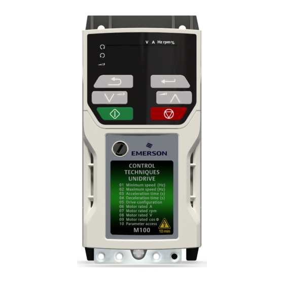
Figure 5-1 Unidrive M100 keypad detail Figure 5-2 Unidrive M101 keypad detail V A Hz rpm % V A Hz rpm % (1) The Enter button is used to enter parameter view or edit mode, or to accept a parameter edit. -
Page 20: Saving Parameters
Saving parameters When changing a parameter in Menu 0, the new value is saved when pressing the Enter button to return to parameter view mode from parameter edit mode. If parameters have been changed in the advanced menus, then the change will not be saved automatically. -
Page 21: Basic Parameters (Menu 0)
Basic parameters (Menu 0) Menu 0 is used to bring together various commonly used parameters for basic easy set up of the drive. All the parameters in Menu 0 appear in other menus in the drive. Menus 22 can be used to configure the parameters in Menu 0. - Page 22 Duty Current Rating 00.078 Software Version 0 to 999999 ND NC PT 00.079 User Drive Mode OPEn.LP (1) OPEn.LP (1) ND NC PT US * With Unidrive M101, the default is Pad (5). Read / Read Number Binary Text string Filtered Write...
- Page 23 Unidrive M100-101 Quick Start Guide Issue Number: 6...
- Page 24 Figure 6-1 Menu 0 logic diagram Analog reference 00.016 Analog input Analog input 1 1 mode 01.050 01.015 01.050 Bipolar >1 Reference Drive Enable Configuration 00.017 00.005 Preset frequency reference Preset 00.018 Reference 1 AV.Pr AI.Pr Pad.Ref Keypad reference Input Read-write (RW) 00.XXX terminals...
- Page 25 FORWARD REVERSE AT ZERO FREQUENCY Digital output Maximum Reference Clamp 00.002 Torque Mode 04.011 Selector Minimum Reference Clamp 00.033 00.001 Ramps Motor parameters 00.006 ~ 00.009 Power Factor Rated Voltage Rated Speed 00.003 Rated Current Acceleration Rate 1 00.004 Deceleration Drive Rate 1 00.028...
-
Page 26: Unidrive M100/101 Parameter Descriptions
Unidrive M100/101 parameter descriptions Key: Read / Read Number Binary Text string Filtered Write only parameter parameter parameter Protected Rating Power-down default User save DE Destination copied parameter dependent save value 00.001 {01.007} Minimum Reference Clamp ±VM_NEGATIVE_REF_CLAMP1 Hz 0.00 Hz Set Pr 00.001 at the required minimum output frequency of the drive for both directions of rotation. - Page 27 00.005 {11.034} Drive Configuration AV (0), AI (1), AV.Pr (2), AI.Pr (3), Preset (4), Pad (5), Pad.Ref (6), AV (0) torque (8) Use Pr 00.005 to select the required frequency/speed reference as follows: Value Text Description Analog input 1 (voltage) Analog input 1 (current) AV.Pr Analog input 1 (voltage) or 3 presets selected by terminal...
- Page 28 00.008 {05.009} Motor Rated Voltage 110 V drive: 230 V 200 V drive: 230 V 0 to VM_AC_VOLTAGE_SET 400 V drive 50 Hz: 400 V 400 V drive 60 Hz: 460 V The Rated Voltage (00.008) and the Rated Frequency (00.039) are used to define the voltage to frequency characteristic applied to the motor.
- Page 29 00.015 {01.005} Jog Reference 0.00 to 300.00 Hz 1.50 Hz Defines the reference when jog is enabled. 00.016 {07.007} Analog Input 1 Mode 4-20.S (-6), 20-4.S (-5), 4-20.L (-4), 20-4.L (-3), 4-20.H (-2), 20-4.H (-1), Volt (6) 0-20 (0), 20-0 (1), 4-20.tr (2), 20-4.tr (3), 4-20 (4), 20-4 (5), Volt (6) Defines the mode of analog input 1.
- Page 30 00.017 {01.010} Bipolar Reference Enable Off (0) or On (1) Off (0) Pr 00.017 determines whether the reference is uni-polar or bi-polar. See Minimum Reference Clamp (00.001). Allows negative speed reference in keypad mode. 00.018 {01.021} Preset Reference 1 ±VM_SPEED_FREQ_REF 0.00 Hz If the preset reference has been selected (see Pr 00.005), the speed at which the motor runs is determined by this parameter.
- Page 31 00.028 {02.004} Ramp Mode Select Fast (0), Std (1), Std.bst (2), Std (1) Fst.bst (3) Defines the mode used by the ramp system. 0: Fast ramp 1: Standard ramp 2: Standard ramp with motor voltage boost 3: Fast ramp with motor voltage boost Fast ramp is linear deceleration at programmed rate, normally used when a braking resistor is installed.
- Page 32 00.031 {06.001} Stop Mode Coast (0), rp (1), rp.dc I (2), dc I (3), rp (1) td.dc I (4), dis (5), No.rp (6) Defines how the motor is controlled when the run signal is removed from the drive. Value Text Description Coast Coast stop...
- Page 33 00.035 {08.091} DO1 Control (terminal 10) 0-21 Defines the behaviour of digital output 1. Value Description User defined by Digital IO1 Source/Destination A, Digital IO2 Source/Destination A, Relay 1 Output Source A, or Relay 2 Output Source A. Drive running signal (RUN) Frequency arrived signal (FAR) Frequency level detection signal (FDT1) Frequency level detection signal (FDT2)
- Page 34 00.037 {05.018} Maximum Switching Frequency 0.667 (0), 1 (1), 2 (2), 3 (3), 4 (4), 3 (3) kHz 6 (5), 8 (6), 12 (7), 16 (8) kHz Defines the maximum switching frequency that can be used by the drive. Pr 00.037 Text Description 0.667...
- Page 35 00.039 {05.006} Motor Rated Frequency 0.00 to VM_SPEED_FREQ_REF_ 50 Hz: 50.00 Hz UNIPOLAR Hz 60 Hz: 60.00 Hz Enter the value from the rating plate of the motor. Defines the voltage to frequency ratio applied to the motor. 00.040 {05.011} Number Of Motor Poles Auto (0) to 32 (16) Auto (0)
- Page 36 00.069 {05.040} Spin Start Boost 0.0 to 10.0 Spin Start Boost (00.069) is used by the algorithm that detects the frequency of a spinning motor when the drive is enabled and Catch A Spinning Motor (00.033) ≥ 1. For smaller motors the default value of 1.0 is suitable, but for larger motors Spin Start Boost (00.069) may need to be increased.
-
Page 37: Running The Motor
Running the motor This section takes a new user through all the essential steps to running a motor for the first time. Table 7-1 Open Loop Action Detail Ensure: • The drive enable signal is not given, terminal 11 is open •... -
Page 38: Diagnostics
Diagnostics Users must not attempt to repair a drive if it is faulty, nor carry out fault diagnosis other than through the use of the diagnostic features described in this chapter. If a drive is faulty, it must be returned to the supplier of the drive for repair. WARNING Table 8-1 Trip indications Trip... - Page 39 Trip Condition Description code The cause of the trip can be identified from the sub trip number displayed after the trip string. Sub-trip Reason An External trip is initiated External Trip = 1 Refer to Drive User Guide. FAN.F Fan fail Indicates the fan or fan circuitry has failed Fi.Ch File changed...
- Page 40 Trip Condition Description code OI.SC Output phase short-circuit Over-current detected on drive output when enabled. Out.P Output phase loss detected Phase loss has been detected at the drive output. The OV trip indicates that the DC bus voltage has exceeded the maximum limit.
-
Page 41: Alarm Indications
Alarm indications In any mode, an alarm is an indication given on the display by alternating the alarm string with the drive status string display. If an action is not taken to eliminate any alarm except "tuning and LS" the drive may eventually trip. -
Page 42: Nv Media Card Operation
NV Media Card Operation Figure 9-1 Installing the AI-Backup adaptor (SD Card) 1. Identify the two plastic fingers on the underside of the AI-Backup adaptor (1) - then insert the two fingers into the corresponding slots in the spring-loaded sliding cover on the top of the drive. 2. -
Page 43: Ul Listing Information
UL listing information 10.1 General Drive sizes 1 to 4 have been assessed to meet both UL and cUL requirements. UL listings can be viewed online at www.UL.com. The UL file number is E171230. 10.2 Mounting Drives can be installed in the following configurations: •... -
Page 44: Cul Requirements For Frame Size 4
10.7 cUL requirements for frame size 4 For frame size 4, models Mxxx-042 00133A, Mxxx-042 00176A, Mxxx-044 00135A and Mxxx-044 00170A, transient surge suppression shall be installed on the line side of this equipment and shall be rated 480 Vac (phase to ground), 480 Vac (phase to phase), suitable for overvoltage category III, and shall provide protection for a rated impulse withstand voltage peak of 6 kV and a clamping voltage of maximum 2400 V. -
Page 45: Group Installation
10.11 Group installation 10.11.1 Definition Group Installation Definition: A motor branch circuit for two or more motors, or one or more motors with other loads, protected by a circuit breaker or a single set of fuses. 10.11.2 Limitations on use All motors rated less than 1 hp The drives may be used in group installations where each of the motors is rated 1 hp or less. - Page 46 Digital I/O Analog I/O 24 V user Analog input 1 Digital I/O1 Frequency Zero frequency reference 10 V user Digital Input 2 Drive enable Digital input 3 Run forward Digital input 4 DC bus/Brake Run reverse Relay Drive ok AC supply Motor 1 ph/3 ph AC power...
Need help?
Do you have a question about the Unidrive M101 and is the answer not in the manual?
Questions and answers