Table of Contents
Advertisement
VL-Z400S/H
VL-Z500S/H/E
1. SPECIFICATIONS .............................................................................................................................. 2
2. PART NAMES .................................................................................................................................... 3
3. DISASSEMBLY OF THE SET ............................................................................................................ 4
4. MECHANISM ADJUSTMENT JIGS AND PARTS .............................................................................. 8
5. INSPECTION AND MAINTENANCE
ITEMS AND INTERVALS ................................................................................................................... 9
6. ADJUSTING AND CHECKING OF MECHANISM ........................................................................... 10
7. ADJUSTMENT OF RUNNING SYSTEM .......................................................................................... 13
8. ASSEMBLING OF MECHANISM SECTION AND PART REPLACEMENT
(DISASSEMBLING AND ASSEMBLING) ........................................................................................... 15
9. METHOD OF ADJUSTING THE ELECTRIC CIRCUIT .................................................................... 25
10.USEFUL TIPS ................................................................................................................................... 44
11.SIGNAL FLOW DIAGRAMS ............................................................................................................. 45
12.BLOCK DIAGRAMS ......................................................................................................................... 48
13.SCHEMATIC DIAGRAMS ................................................................................................................ 56
14.SEMICONDUCTOR LEAD IDENTIFICATION ............................................................................... 130
15.PRINTED WIRING BOARD ASSEMBLIES .................................................................................... 132
16.REPLACEMENT PARTS LIST ....................................................................................................... 149
17.PACKING OF THE SET ................................................................................................................. 172
SERVICE MANUAL
LIQUID CRYSTAL DISPLAY CAMCORDER
MODELS
In the interests of user-safety (Required by safety regula-
tions in some countries) the set should be restored to its
original condition and only parts identical to those specified
be used.
CONTENTS
SHARP CORPORATION
1
VL-Z400S-T/H-T
VL-Z500S-S/H-S/E-T/E-S
S45T2VL-Z400S
VL-Z400S-T
VL-Z400H-T
VL-Z500S-S
VL-Z500H-S
VL-Z500E-T
VL-Z500E-S
Page
PAL
Advertisement
Table of Contents

Related Manuals for Sharp VL-Z400H-T


Summary of Contents for Sharp VL-Z400H-T
- Page 1 VL-Z400S-T/H-T VL-Z500S-S/H-S/E-T/E-S SERVICE MANUAL S45T2VL-Z400S LIQUID CRYSTAL DISPLAY CAMCORDER VL-Z400S-T VL-Z400H-T VL-Z500S-S VL-Z500H-S VL-Z400S/H VL-Z500E-T VL-Z500E-S MODELS In the interests of user-safety (Required by safety regula- tions in some countries) the set should be restored to its original condition and only parts identical to those specified be used.
-
Page 2: Specifications
VL-Z400S-T/H-T VL-Z500S-S/H-S/E-T/E-S 1. SPECIFICATIONS Signal System: PAL standard Recording System: 2 rotary heads, helical scanning system Cassette: Digital VCR Mini DV video cassette Recording/Playback Time: 90 minutes (DVM60, LP mode) Tape Speed: SP mode: 18.831mm/second LP mode: 12.568 mm/second Pickup Device: "... -
Page 3: Part Names
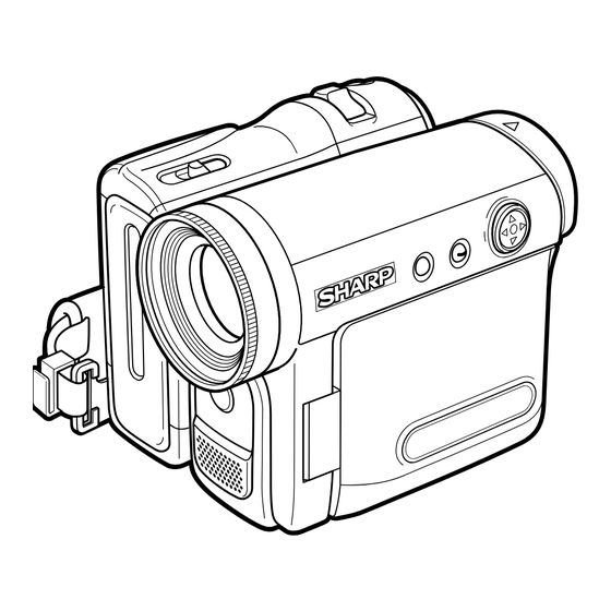
VL-Z400S-T/H-T VL-Z500S-S/H-S/E-T/E-S 2. PART NAMES Front view Front view VL-Z400S/H VL-Z500S/H/E Operation button Operation button Zoom lens Zoom lens Built-in LED video DISPLAY/MODE SET button/ DISPLAY/MODE SET button/ light LCD LAMP button LCD LAMP button Stereo microphone Stereo microphone MENU button MENU button Left view Right view... -
Page 4: Disassembly Of The Set
VL-Z400S-T/H-T VL-Z500S-S/H-S/E-T/E-S 3. DISASSEMBLY OF THE SET 3-1. Procedure for disassembling the cabinet Note: Before removing the cabinet, turn OFF the power and make sure that the battery is not connected. · Remove the screw ((s) XiPSF14P06000). LCD panel · Open the LCD panel 90 degrees and remove the two screws ((x) LX- HZ0050TAFN). - Page 5 VL-Z400S-T/H-T VL-Z500S-S/H-S/E-T/E-S Mechanism reversion detection PWB unit Camera top cover PWB mounting angle Camera unit FPC(2) FPC(3) FPC(1) · Remove the screw ((x) LX-HZ0050TAFN), screw ((p) LX- · Remove the screw ((b) XiPSN17P03000) and remove the HZ0063TAFN) and screw ((a) XiPSN17P02000), remove the Mechanism reversion detection PWB unit.
- Page 6 VL-Z400S-T/H-T VL-Z500S-S/H-S/E-T/E-S 3-2. Procedure for disassembling the cabinet · Remove the three screws Z500E-T: ((e) XiPSF17P03000) or Z400/ Z500S-S/H-S/E-S: ((b) XiPSN17P03000) remove the screw Z500E- T: ((d) XiPSF17P02000) or Z400/Z500S-S/H-S/E-S: ((a) XiPSN17P02000) and remove the VCR bottom cover. VCR bottom cover ·...
- Page 7 VL-Z400S-T/H-T VL-Z500S-S/H-S/E-T/E-S · Disconnect the six FPCs of the head amp circuit board Mechanism unit. · Remove the two screws ((a) XiPSN17P02000) and remove the head amp PWB unit. · Remove the three screws ((w) LX-BZA022WJFN) and remove the screw ((k) LX-BZA023WJFD). ·...
- Page 8 VL-Z400S-T/H-T VL-Z500S-S/H-S/E-T/E-S Sketch 1. Name 4. MECHANISM ADJUSTING JIGS AND PARTS 2. Part code 3. Code 4-1. Mechanism checking and adjusting jigs <Note: Order of descriptions> * Model number and usage 1. Tension gauge 4N 1. Dial tension gauge 1. Cassette torque 1.
-
Page 9: Inspection And Maintenance Items And Intervals
VL-Z400S-T/H-T VL-Z500S-S/H-S/E-T/E-S 5. INSPECTION AND MAINTENANCE ITEMS AND INTERVALS In order to maintain the quality of the mechanism section, perform the following maintenance and inspection. After repairing the mechanism section, perform the following maintenance regardless of the number of hours of use by the user. 5-1. -
Page 10: Adjusting And Checking Of Mechanism
VL-Z400S-T/H-T VL-Z500S-S/H-S/E-T/E-S 6. ADJUSTING AND CHECKING OF MECHANISM The items described here are relevant to the general on-site servicing (field service). This section does not cover adjustment and replacement for which sophisticated equipment, jigs and techniques are required. In order to maintain the initial characteristics of the mechanism, it is necessary to perform maintenance and inspection and also it is essential not to damage the tape etc. - Page 11 VL-Z400S-T/H-T VL-Z500S-S/H-S/E-T/E-S 6-4. Checking and adjusting of tension pole position during Tension pole position (Based on drum base outside shape) REC (PB) 3 to 4V DC, Cassette controller assembly not installed (Mechanism only) 0±0.3 Drum base (1) Checking T pole Check that the tension pole is located in the prescribed position as shown in Fig.4 at the start of a 60-minute tape.
- Page 12 VL-Z400S-T/H-T VL-Z500S-S/H-S/E-T/E-S 6-7. Checking of loading back tension 3 to 4V DC, Cassette controller assembly not installed (Mechanism only) (1) Apply 3 to 4V DC to the loading motor and select the L start mode. (See 8-1.) (2) Move the swing arm to the S reel table side. At this time, take care not to damage the gears etc.
-
Page 13: Adjustment Of Running System
VL-Z400S-T/H-T VL-Z500S-S/H-S/E-T/E-S 7. ADJUSTMENT OF RUNNING SYSTEM 7-1. Outline of adjustment of running system (Replacement parts) · Tu guide and arm Readjustment of height · Slide chassis · T arm Ass'y Preparations for Final adjustment Coarse adjustment adjustment of Installation of of Running system of Running system Running system... - Page 14 VL-Z400S-T/H-T VL-Z500S-S/H-S/E-T/E-S 7-4. Coarse adjustment of running system (Cassette controller installed) 1. Adjustment of height of Su and Tu guide rollers <Method and description> Inlet side Outlet side (1) Play back the alignment tape for running system adjustment and make adjustment so that the inlet ±1/4 shift ±1/4 shift Normal...
-
Page 15: Assembling Of Mechanism Section And Part Replacement
VL-Z400S-T/H-T VL-Z500S-S/H-S/E-T/E-S 8. ASSEMBLING OF MECHANISM SECTION AND PART REPLACEMENT (DISASSEMBLING AND ASSEMBLING) This section describes the method of assembling the mechanism section and the method of part replacement. For how to remove the cabinet etc., refer to "3. DISASSEMBLY OF THE SET". <Cautions>... - Page 16 VL-Z400S-T/H-T VL-Z500S-S/H-S/E-T/E-S (5) PB (Record, Fast forward, Fast rewind, VSF and VSR) mode This mode is used for playback, recording, fast-forwarding, fast -rewinding, VSF and VSR. In this mode, the pinch roller is pressed against the capstan shaft and the S main brake is located away from the S reel table.
- Page 17 VL-Z400S-T/H-T VL-Z500S-S/H-S/E-T/E-S Fig.7 Fig.8 8-3. Method of operating on the circuit board with the cassette controller assembly removed If this method is performed improperly, the tape may be damaged. Therefore do not use this method except in special cases such as measuring the VSR torque. Be sure to follow the cautions shown in this manual. (1) Apply 3 to 4V DC to the loading motor to establish the standby mode.
- Page 18 VL-Z400S-T/H-T VL-Z500S-S/H-S/E-T/E-S 8-4. Phase-adjust Phase-adjust the following parts. (1) Mode SW (2) Main cam (3) Sub cam (The main cam and sub cam should be also phase-adjusted for the chassis.) (4) S loading arm (5) Tu loading arm (6) Loading drive gear (main cam, sub cam, S loading gear) Note) Check the marker position carefully before disassembling.
- Page 19 VL-Z400S-T/H-T VL-Z500S-S/H-S/E-T/E-S 8-5. Assembling method 8-5-1. Method of assembling the main chassis assembly Note) For reference, numbers are prefixed to parts names to show the sequence of assembly. (For the greasing/oiling and cleaning locations, refer to the diagram of greasing/oiling locations.) (2)LM/Mode FPC (1)T pole base loading arm ass'y...
- Page 20 VL-Z400S-T/H-T VL-Z500S-S/H-S/E-T/E-S 8-5-2. Method of assembling the slide chassis assembly (8)Guide nut (6)Tu guide flange (7)Tu guide (14)Tu reel table ass'y (13)S reel table ass'y (1)Slide adjustment (2)T-SPR adjustment (6)Tu guide flange (11)T main brake (5)Guide adjustment SPR (4)Tu guide arm (16)S brake SPR ass'y (9)VSR brake lever...
- Page 21 VL-Z400S-T/H-T VL-Z500S-S/H-S/E-T/E-S 8-5-3. Method of combining the main chassis assembly and the slide chassis assembly (1) Position the assemblies as shown in the figure below (the pole base is slightly protruded). (2) Insert the operation pins (tension arm, Tu guide arm) of the slide chassis assembly into the locations of the main chassis assembly shown in the figure below, fit the SL drive lever pin of the main chassis assembly into the groove of the slide chassis (the groove of the slide adjustment ANG), and then fix with the two screws.
- Page 22 VL-Z400S-T/H-T VL-Z500S-S/H-S/E-T/E-S 8-5-4. Diagram of greasing/oiling locations...
- Page 23 VL-Z400S-T/H-T VL-Z500S-S/H-S/E-T/E-S 8-6. Method of installing the cassette controller (2)Completed cassette controller (1)Main slide Left side view Right side view ass'y (3)Down guide Right side view Left side view B-1,2 Left side view Right side view (4)Cassette cover Right side view Right side view Mechanism viewed from above C: Move down the cassette controller by pushing this...
- Page 24 VL-Z400S-T/H-T VL-Z500S-S/H-S/E-T/E-S 8-7. Method of taking out the cassette with the mechanism operating singly (1) Apply 3 to 4V DC to the loading motor for slight unloading. (2) If the tape is slack, turn the rotor (mechanism backside) of the capstan motor by hand to take up the slack in the tape. (3) Repeat steps (1) and (2) above.
-
Page 25: Method Of Adjusting The Electric Circuit
VL-Z400S-T/H-T VL-Z500S-S/H-S/E-T/E-S 9. METHOD OF ADJUSTING THE ELECTRIC CIRCUIT -Before making adjustment- · It seems that, in most cases, this adjusting method is used when it becomes necessary to adjust the electric circuit as a result of replacement of worn mechanism parts or the video head. When adjusting the electric circuit, check that the mechanism operates properly (the mechanism is adjusted completely). - Page 26 VL-Z400S-T/H-T VL-Z500S-S/H-S/E-T/E-S VL-Z400S-T/H-T/Z500S-S/H-S/E-T/E-S Service jig configuration...
- Page 27 VL-Z400S-T/H-T VL-Z500S-S/H-S/E-T/E-S [TEST POINT] (Wiring board diagram: Main Side A) TL3304 TL3302 TL923 TL922 L917 L916 L918 SC3301 SC3302 TL902 C974 C973 TL3310 TL913 R3321 Q908 C3321 C975 C3320 IC706 Q911 X702 R990 C980 R932 Q703 C728 R754 R749 R768 TL901 C711 C709...
- Page 28 VL-Z400S-T/H-T VL-Z500S-S/H-S/E-T/E-S (Wiring board diagram: Sub Side A) TL1470 Checking of EE level Checking of f characteristics TL1472 TL1474 TL1475 Checking of EE level PCO_D/A-Y ADJ PCO_D/A-C ADJ Checking of f characteristics VA602 C601 R604 C2905 C2906 R7427 C1501 R1501 C1503 R1502 C1502...
- Page 29 VL-Z400S-T/H-T VL-Z500S-S/H-S/E-T/E-S [Execution of adjustment] Adjustment of servo and system controller 1. System code setting It is necessary to set the following data items after replacing IC705 (E PROM). <Adjusting method> Select the VCR adjustment mode and set the data value at each address. Code Specifications Destination...
- Page 30 VL-Z400S-T/H-T VL-Z500S-S/H-S/E-T/E-S 3. Adjustment of shutdown Mode VCR ADJ mode Adjusting 1) Set a recordable tape and select the camera mode. 2) Press "CONTINUE" → "TEST SEL" on the adjustment remote control to enter the TEST mode (T-01 flashing). method 3) Select T-03 with the FF and REW keys and press "PB"...
- Page 31 VL-Z400S-T/H-T VL-Z500S-S/H-S/E-T/E-S 3. Check of electromagnetic conversion circuit system (Auto check of playback envelope signal quality and error rate) Mode VCR adjustment mode Procedure 1) Insert a recordable tape and enter the VCR mode. 2) Press the "CONTINUE" → "TEST SEL" keys on the remote control for adjustment to enter the TEST mode. ("T-01"...
- Page 32 VL-Z400S-T/H-T VL-Z500S-S/H-S/E-T/E-S 3. Adjustment of VF_DAC full scale (Main PWB) Measurement point TL7824(VF_G_OUT) Address VCR ADJ 59D Procedure 1) Set the data values at addresses 587 (GRYLEV)/58C (γ PEAK)/5EB (TESTSW2) and 5E6 (OSDSW) to FF/80/77 and 00, respectively. (The LED shows nothing.) 2) Set the data values at addresses 59F (CLAMP)/58D (PEDESTAL) and 5B7 (VCLK3 INV) to 00/80 and 48, respectively.
- Page 33 VL-Z400S-T/H-T VL-Z500S-S/H-S/E-T/E-S ADJUSTMENT OF LCD CIRCUIT When making this adjustment, set the backlight switch to "Normal". (Wiring board diagram: Main Side A) R1825 C1808 R1803 R4401 R1824 C1814 R1828 L1803 TL1812 D6800 C1815 R1816 C1406 C1813 C1812 R6805 C6804 TL7824 TL1451 R1419 L1802...
- Page 34 VL-Z400S-T/H-T VL-Z500S-S/H-S/E-T/E-S ADJUSTMENT OF MIC AMP CIRCUIT (Wiring board diagram: Sub Side A) SC1501 R1511 R1513 R1512 TL1470 TL1472 D3601 Checking of EE level Checking of EE level D3600 C521 Checking of f characteristics Checking of f characteristics VA501 C522 Q2903 R2917 R2904...
- Page 35 1. Connect with the EUI48/64 ID code control system. (1) Start the Internet Explorer or Netscape Navigator. (2) Access the following address.(URL: http://www.rcg.kami.sharp.co.jp/quics/index.html) Select "EUI48/64 ID code control system" among the "Service" items. Note: If you want to establish a connection by directly inputting the URL, please input the following.
- Page 36 VL-Z400S-T/H-T VL-Z500S-S/H-S/E-T/E-S (5) Click on [Repair use]. Click (6) Input the necessary information for the application. Be sure to input the necessary input items. Select the [Group/company] and [Kind name] from the list. Input the [Model name] in half-size characters. Input the [Serial number] in half-size characters.
- Page 37 VL-Z400S-T/H-T VL-Z500S-S/H-S/E-T/E-S 9-2. Adjustment of camera section 9-2-1. Servicing of camera section (1) Camera adjustment should be performed with the set completed. (2) Subjects, measuring instruments and jigs necessary for servicing and adjustment of the camera section • Gray scale chart •...
- Page 38 VL-Z400S-T/H-T VL-Z500S-S/H-S/E-T/E-S 3) Description of remote control keys "FF" key: It is used to increase the address value and data value. "REW" key: It is used to decrease the address value and data value. "PLAY" key: It is used to confirm the selected address to call up the data. It is also used to confirm the data value. "STOP"...
- Page 39 VL-Z400S-T/H-T VL-Z500S-S/H-S/E-T/E-S (4) Camera signal system adjustment mode In the camera signal system adjustment mode, the auto white balance function is stopped in order to adjust the camera. In this mode, the white balance is set to the indoor mode and focussing is performed manually. 1) How to enter the camera signal system adjustment mode Set the data value at address "0000"...
- Page 40 VL-Z400S-T/H-T VL-Z500S-S/H-S/E-T/E-S 9-2-4. Adjusting procedure Adjustment method Item (1) Adjustment of auto focus The following adjustments are performed automatically by establishing the auto focus adjustment mode and writing the following data at address "13FD" sequentially. The adjustment items are as shown in the table below. When an adjustment is completed normally, data "FF"...
- Page 41 VL-Z400S-T/H-T VL-Z500S-S/H-S/E-T/E-S Adjustment method Item (4) Rough adjustment of iris AE 1) While shooting the gray scale normally, observe the video output using the oscilloscope. • Measurement terminal: By rewriting the data at address "0002", adjust the white luminance signal level to S terminal luminance signal output 680±10mVp-p and the gray luminance signal level (on the gray scale background) to (75 Ω...
- Page 42 VL-Z400S-T/H-T VL-Z500S-S/H-S/E-T/E-S Adjustment method Item 1) Perform the adjustment of white balance repeatedly. (7) Adjustment of white balance • Measurement terminal: EE output • Address: "0090" INDOOR_W/B R "0092" INDOOR_W/B R • Measuring instrument: Vector scope • Object: Grey scale •...
-
Page 43: Table Of Contents
VL-Z400S-T/H-T VL-Z500S-S/H-S/E-T/E-S When performing (1) replacement of EEPROM or (2) replacement of MAIN board, write the following data and make adjustments to the camera. Parameter list for servicing Z500S ADDRESS Variable parameter ADDRESS Variable parameter ADDRESS Variable parameter ADDRESS Variable parameter (CAM ADJ) (CAM ADJ) (CAM ADJ) - Page 44 VL-Z400S-T/H-T VL-Z500S-S/H-S/E-T/E-S 10. USEFUL TIPS (PROBLEMS DIFFER FROM THOSE FOUND ON VHS OR 8MM DECKS BECAUSE THE SIGNALS ARE DIGITALLY PROCESSED.) Camera (EE mode) Camera (REC mode) VCR (EE mode) VCR (PB mode) Picture fails to appear when tape Picture fails Blueback fails recorded on this to appear...
-
Page 45: Signal Flow Diagrams
VL-Z400S-T/H-T VL-Z500S-S/H-S/E-T/E-S 11. SIGNAL FLOW DIAGRAMS 11-1. EE MODE FLOW (VIDEO) WAVEFORM DIAGRAM (DURING COLOR BAR RECORDING) IC4401 336pin Y Output 20µs/d CH1=500mV DC P*10 CAM ADIN 370 371 373 375 377 378 380 CAM VIO ENGINE IC4401 IC4401 254pin CDY3 Output VIDEO I/O IC1401 IC1800... - Page 46 VL-Z400S-T/H-T VL-Z500S-S/H-S/E-T/E-S WAVEFORM DIAGRAM 11-3. FLOW IN PB MODE (VIDEO) (DURING COLOR BAR PLAYBACK) HEAD AMP IC3401 5pin PBDATA Input PB_DATA IC3401 43pin Input P3301 50nSEC/d 1V/d PB_DATA IC3401 EQ/PLL 36 39 PB-CLK ADIN REC/PB ENGINE IC452 IC3401 33~36, 39~42pin Output 50nSEC/d 1V/d 262 264...
- Page 47 VL-Z400S-T/H-T VL-Z500S-S/H-S/E-T/E-S 11-5. FLOW IN PB MODE (AUDIO) WAVEFORM DIAGRAM (1.6 kHz SINE WAVE) From IC3404 same as in Video PB system 10µs/d CH1=1V DC P*10 IC452 REC/PB ENGINE DODAT 16Bit ADC/DAC IC1602 AUD-R_DA_OUT AUD-L_DA_OUT HP-L IC600 HP-COMMON HP-R AUDIO-R_IN/OUT SP(+) AUDIO-L_IN/OUT SP(-)
-
Page 48: Block Diagrams
VL-Z400S-T/H-T VL-Z500S-S/H-S/E-T/E-S 12. BLOCK DIAGRAMS 12-1. SYSTEM BLOCK DIAGRAM... - Page 49 VL-Z400S-T/H-T VL-Z500S-S/H-S/E-T/E-S 12-2. CAMERA SECTION BLOCK DIAGRAM...
- Page 50 VL-Z400S-T/H-T VL-Z500S-S/H-S/E-T/E-S 12-3. VIO ENGINE SECTION BLOCK DIAGRAM (VL-Z400)
- Page 51 VL-Z400S-T/H-T VL-Z500S-S/H-S/E-T/E-S 12-3. VIO ENGINE SECTION BLOCK DIAGRAM (VL-Z500)
- Page 52 VL-Z400S-T/H-T VL-Z500S-S/H-S/E-T/E-S 12-4. REC/PB SECTION BLOCK DIAGRAM...
- Page 53 VL-Z400S-T/H-T VL-Z500S-S/H-S/E-T/E-S 12-5. AUDIO/DIGITAL OUTPUT SECTION BLOCK DIAGRAM...
- Page 54 VL-Z400S-T/H-T VL-Z500S-S/H-S/E-T/E-S 12-6. CAMERA CIRCUIT BLOCK DIAGRAM...
- Page 55 VL-Z400S-T/H-T VL-Z500S-S/H-S/E-T/E-S - M E M O -...
-
Page 56: Schematic Diagrams
VL-Z400S-T VL-Z400S-T VL-Z500S-S/H-S/E-T/E-S VL-Z500S-S/H-S/E-T/E-S 13. SCHEMATIC DIAGRAMS 13-1. OVERALL SCHEMATIC DIAGRAM DUNTKC363QA52(VL-Z500S-S/S-S(AS)) DUNTKC363QA53(VL-Z500S-S(RS)) DUNTKC363QA54(VL-Z500E-T/E-T(WT)/E-T(XT)/E-S/E-S(WS)) DUNTKC363QA55(VL-Z500H-S) DUNTKC363QA56(VL-Z400S-T) DUNTKC363QA57(VL-Z400H-T) DUNTKC367QA53(VL-Z500S-S/S-S(AS)/S-S(RS)/H-S/E-T/ E-T(WT)/E-T(XT)/E-S/E-S(WS)) DUNTKC367QA54(VL-Z400S-T/H-T) VL-Z500 only... - Page 57 VL-Z400S-T VL-Z400S-T VL-Z500S-S/H-S/E-T/E-S VL-Z500S-S/H-S/E-T/E-S 13-2. REC/PB ENGINE SCHEMATIC DIAGRAM (VL-Z400)
- Page 58 VL-Z400S-T VL-Z400S-T VL-Z500S-S/H-S/E-T/E-S VL-Z500S-S/H-S/E-T/E-S 13-2. REC/PB ENGINE SCHEMATIC DIAGRAM (VL-Z500)
- Page 59 VL-Z400S-T VL-Z400S-T VL-Z500S-S/H-S/E-T/E-S VL-Z500S-S/H-S/E-T/E-S 13-3. MEC/SYS MiCON SCHEMATIC DIAGRAM...
- Page 60 VL-Z400S-T VL-Z400S-T VL-Z500S-S/H-S/E-T/E-S VL-Z500S-S/H-S/E-T/E-S 13-4. POWER1 SCHEMATIC DIAGRAM...
- Page 61 VL-Z400S-T VL-Z400S-T VL-Z500S-S/H-S/E-T/E-S VL-Z500S-S/H-S/E-T/E-S 13-5. CAMERA CONN SCHEMATIC DIAGRAM(VL-Z400)
- Page 62 VL-Z400S-T VL-Z400S-T VL-Z500S-S/H-S/E-T/E-S VL-Z500S-S/H-S/E-T/E-S 13-5. CAMERA CONN SCHEMATIC DIAGRAM(VL-Z500)
- Page 63 VL-Z400S-T VL-Z400S-T VL-Z500S-S/H-S/E-T/E-S VL-Z500S-S/H-S/E-T/E-S 13-6. VIDEO I/O SCHEMATIC DIAGRAM (VL-Z400)
- Page 64 VL-Z400S-T VL-Z400S-T VL-Z500S-S/H-S/E-T/E-S VL-Z500S-S/H-S/E-T/E-S 13-6. VIDEO I/O SCHEMATIC DIAGRAM (VL-Z500)
- Page 65 VL-Z400S-T VL-Z400S-T VL-Z500S-S/H-S/E-T/E-S VL-Z500S-S/H-S/E-T/E-S 13-7. LCDIF SCHEMATIC DIAGRAM...
- Page 66 VL-Z400S-T VL-Z400S-T VL-Z500S-S/H-S/E-T/E-S VL-Z500S-S/H-S/E-T/E-S 13-8. CONNECTION(B-B) SCHEMATIC DIAGRAM...
- Page 67 VL-Z400S-T VL-Z400S-T VL-Z500S-S/H-S/E-T/E-S VL-Z500S-S/H-S/E-T/E-S 13-9. EQ/PLL SCHEMATIC DIAGRAM...
- Page 68 VL-Z400S-T VL-Z400S-T VL-Z500S-S/H-S/E-T/E-S VL-Z500S-S/H-S/E-T/E-S 13-10. CAM/CARD MiCON SCHEMATIC DIAGRAM...
- Page 69 VL-Z400S-T VL-Z400S-T VL-Z500S-S/H-S/E-T/E-S VL-Z500S-S/H-S/E-T/E-S 13-11. CAMERA VIDEO I/O ENGINE SCHEMATIC DIAGRAM (VL-Z400)
- Page 70 VL-Z400S-T VL-Z400S-T VL-Z500S-S/H-S/E-T/E-S VL-Z500S-S/H-S/E-T/E-S 13-11. CAMERA VIDEO I/O ENGINE SCHEMATIC DIAGRAM (VL-Z500)
- Page 71 VL-Z400S-T VL-Z400S-T VL-Z500S-S/H-S/E-T/E-S VL-Z500S-S/H-S/E-T/E-S 13-12. DAC SCHEMATIC DIAGRAM...
- Page 72 VL-Z400S-T VL-Z400S-T VL-Z500S-S/H-S/E-T/E-S VL-Z500S-S/H-S/E-T/E-S 13-13. VFIF SCHEMATIC DIAGRAM...
- Page 73 VL-Z400S-T VL-Z400S-T VL-Z500S-S/H-S/E-T/E-S VL-Z500S-S/H-S/E-T/E-S 13-14. CCD SCHEMATIC DIAGRAM...
- Page 74 VL-Z400S-T VL-Z400S-T VL-Z500S-S/H-S/E-T/E-S VL-Z500S-S/H-S/E-T/E-S 13-15. TG SCHEMATIC DIAGRAM...
- Page 75 VL-Z400S-T VL-Z400S-T VL-Z500S-S/H-S/E-T/E-S VL-Z500S-S/H-S/E-T/E-S 13-16. CDS SCHEMATIC DIAGRAM...
- Page 76 VL-Z400S-T VL-Z400S-T VL-Z500S-S/H-S/E-T/E-S VL-Z500S-S/H-S/E-T/E-S 13-17. LCONN SCHEMATIC DIAGRAM...
- Page 77 VL-Z400S-T VL-Z400S-T VL-Z500S-S/H-S/E-T/E-S VL-Z500S-S/H-S/E-T/E-S 13-18. EXT DAC SCHEMATIC DIAGRAM...
- Page 78 VL-Z400S-T VL-Z400S-T VL-Z500S-S/H-S/E-T/E-S VL-Z500S-S/H-S/E-T/E-S 13-19. LENS SCHEMATIC DIAGRAM...
- Page 79 VL-Z400S-T VL-Z400S-T VL-Z500S-S/H-S/E-T/E-S VL-Z500S-S/H-S/E-T/E-S 13-20. AUDIO I/O SCHEMATIC DIAGRAM (VL-Z400)
- Page 80 VL-Z400S-T VL-Z400S-T VL-Z500S-S/H-S/E-T/E-S VL-Z500S-S/H-S/E-T/E-S 13-20. AUDIO I/O SCHEMATIC DIAGRAM (VL-Z500)
- Page 81 VL-Z400S-T VL-Z400S-T VL-Z500S-S/H-S/E-T/E-S VL-Z500S-S/H-S/E-T/E-S 13-21. POWER2 SCHEMATIC DIAGRAM å AND SHADED COMPONENTS=SAFETY RELATED PARTS 0.8A 36V å 1.6A 36V å 1.6A 36V...
- Page 82 VL-Z400S-T VL-Z400S-T VL-Z500S-S/H-S/E-T/E-S VL-Z500S-S/H-S/E-T/E-S 13-22. MiC AMP SCHEMATIC DIAGRAM...
- Page 83 VL-Z400S-T VL-Z400S-T VL-Z500S-S/H-S/E-T/E-S VL-Z500S-S/H-S/E-T/E-S 13-23. LCD SCHEMATIC DIAGRAM...
- Page 84 VL-Z400S-T VL-Z400S-T VL-Z500S-S/H-S/E-T/E-S VL-Z500S-S/H-S/E-T/E-S 13-24. INVERTER SCHEMATIC DIAGRAM å AND SHADED COMPONENTS=SAFETY RELATED PARTS å...
- Page 85 VL-Z400S-T VL-Z400S-T VL-Z500S-S/H-S/E-T/E-S VL-Z500S-S/H-S/E-T/E-S 13-25. HEAD AMP SCHEMATIC DIAGRAM...
- Page 86 VL-Z400S-T VL-Z400S-T VL-Z500S-S/H-S/E-T/E-S VL-Z500S-S/H-S/E-T/E-S 13-26. MOTOR DRIVE SCHEMATIC DIAGRAM...
- Page 87 VL-Z400S-T VL-Z400S-T VL-Z500S-S/H-S/E-T/E-S VL-Z500S-S/H-S/E-T/E-S 13-27. OPERATION SCHEMATIC DIAGRAM...
- Page 88 VL-Z400S-T VL-Z400S-T VL-Z500S-S/H-S/E-T/E-S VL-Z500S-S/H-S/E-T/E-S 13-28. LITHIUM SCHEMATIC DIAGRAM...
- Page 89 VL-Z400S-T VL-Z400S-T VL-Z500S-S/H-S/E-T/E-S VL-Z500S-S/H-S/E-T/E-S 13-29. VCR OPERATION SCHEMATIC DIAGRAM...
- Page 90 VL-Z400S-T VL-Z400S-T VL-Z500S-S/H-S/E-T/E-S VL-Z500S-S/H-S/E-T/E-S 13-30. ZOOM SW SCHEMATIC DIAGRAM...
- Page 91 VL-Z400S-T VL-Z400S-T VL-Z500S-S/H-S/E-T/E-S VL-Z500S-S/H-S/E-T/E-S 13-31. INNER LED SCHEMATIC DIAGRAM...
- Page 92 VL-Z400S-T/H-T VL-Z500S-S/H-S/E-T/E-S 13-32. MECHA REVERSION DETECTION SCHEMATIC DIAGRAM...
- Page 93 VL-Z400S-T/H-T VL-Z500S-S/H-S/E-T/E-S 13-33. HOLE SENSOR UNIT SCHEMATIC DIAGRAM...
-
Page 94: Semiconductor Lead Identification
VL-Z400S-T/H-T VL-Z500S-S/H-S/E-T/E-S 14. SEMICONDUCTOR LEAD IDENTIFICATION 3LN01S XP05534 2SC4738Y RT1N144U XP6401 XN04391 7SB3157P FMMT619 15C01M XP4313 XP0431N 2SC5376B 15C01SS XP4601 FDG312P 12A01M 2SC5536 XP6501 12A01SS XP4316 KRC401E MCH6303 KRC654U KRC402E 2SA1362GR RTQ035P02 KRX203U KRC404E 2SA1989R KTC801UY KTA701UY KTA2014EY 2SA5536 KTX101UY EMD12 KTC4075EY XP4501... - Page 95 VL-Z400S-T/H-T VL-Z500S-S/H-S/E-T/E-S HVU17TRF HVC362 EX1394CE HVC375B RB160M30 HVC202A A089WJ 1SS400 MA2S304 LB11993F MB3881++ LA74206W CXD2489R MN52A6CD AN2901FQ UPD16835 CXA2096N LA70050W H49334HN NJM2902V PCM3008 IXA526WJ LC74130W LV4051AT IXA883WJ MB8346BV LA73070V MB88146A R2101S01 UPD16510 NJ12902V MM1323XV PT8146 ADC08351 IXA879WJ LMV358AU IX0785TA NJM2143R IXA204WJ NJM2535V BR24L64F...
- Page 96 VL-Z400S-T/H-T VL-Z400S-T/H-T VL-Z500S-S/H-S/E-T/E-S VL-Z500S-S/H-S/E-T/E-S 15. PRINTED WIRING BOARD ASSEMBLIES MAIN PWB SIDE A TL3304 TL3302 TL923 TL922 L917 L916 L918 SC3301 SC3302 TL902 C974 C973 TL3310 R3321 TL913 Q908 C3321 C975 C3320 IC706 Q911 X702 R990 C980 Q703 R932 C728 R754 R749 R768...
- Page 97 VL-Z400S-T/H-T VL-Z400S-T/H-T VL-Z500S-S/H-S/E-T/E-S VL-Z500S-S/H-S/E-T/E-S SIDE B FDC03 P3303 R952 C923 C983 C1916 R954 R965 C966 R946 SC1204 L904 L919 R960 R948 R949 TL3305 TL3306 TL3307 TL3308 TL3309 R3455 R958 R959 R953 R947 C918 R942 R941 C924 R3453 C920 R957 C919 C917 R925 C916...
- Page 98 VL-Z400S-T/H-T VL-Z500S-S/H-S/E-T/E-S CCD PWB SIDE A C110 C114 C107 R106 IC101 C102 C101 R107 R108 C104 R109 C105 C111 C113 C106 C115 R101 L1051...
- Page 99 VL-Z400S-T/H-T VL-Z500S-S/H-S/E-T/E-S SIDE B R1029 TL1017 TL1009 C1025 TL1025 TL1028 TL1031 TL1011 TL1007 TL1006 TL1005 TL1021 TL1023 SC1001 TL1022 TL1020 TL1024 TL1026 TL1019 TL1016 TL1010 TL1008 R110 R1030 R1028 TL1030 TL1014 TL1002 TL1004 TL1001 TL1012 TL1003 TL14 TL13 TL12 TL11 TL10 TP1003 TL54...
- Page 100 VL-Z400S-T/H-T VL-Z500S-S/H-S/E-T/E-S SIDE A SUB PWB VA602 C601 R604 C2905 C2906 R7427 C1501 R1501 C1503 R1502 C1502 C1508 C1504 R1503 C2904 C1509 C1510 C1505 R1504 C1506 R1505 C1507 R1506 SC1501 R1511 R1513 R1512 D3601 D3600 C521 VA501 C522 Q2903 R2917 R2904 Q2904 R2903...
- Page 101 VL-Z400S-T/H-T VL-Z500S-S/H-S/E-T/E-S SIDE B C553 C573 C562 C554 C574 P3602 C556 R551 L551 C558 C559 R3639 C561 C3646 R552 R553 R3631 R555 C3632 R559 C3634 R3634 R3633 R3646 R654 R3632 R610 C3631 R2556 Q2553 C3629 R2555 R3636 C3615 R607 R623 C3619 R3615 R3617...
- Page 102 VL-Z400S-T/H-T VL-Z500S-S/H-S/E-T/E-S LCD PWB SIDE A SC803 T9800 R9801 C9804 Q9800 C9801 C9806 R9800 R9811 C9807 R9812 R9805 Q9801 R9806 D9800 R825 D800 R826 R827 C817 C818 C807 SC802 R819...
- Page 103 VL-Z400S-T/H-T VL-Z500S-S/H-S/E-T/E-S HEAD AMP PWB SIDE A SIDE B P301 TL1714 TL1713 TL333 T L308 TL309 C323 TL1712 TL1711 TL1710 TL1709 TL1708 TL370 R314 TL369 R303 TL368 C318 C306 C325 TL327 R320 TL326 C321 IC301 TL324 C320 C303 TL323 R305 TL307 R306 TL325...
- Page 104 VL-Z400S-T/H-T VL-Z500S-S/H-S/E-T/E-S OPERATION PWB SIDE A SIDE B C2002 C2001 C2007 C2011 C2010...
- Page 105 VL-Z400S-T/H-T VL-Z500S-S/H-S/E-T/E-S LITHIUM PWB SIDE A C5804 J5800 SIDE B C5802 TL5806 C5803 R5807 R5804 R5801 R5808 TL5813 C5800 TL5812 TL5810 TL5801 TL5811 TL5818 SC5800 TL5814 TL5800...
- Page 106 VL-Z400S-T/H-T VL-Z500S-S/H-S/E-T/E-S MECHA REVERSION DETECTION PWB SIDE A SIDE B TL2302 SW2300 TL2301...
- Page 107 VL-Z400S-T/H-T VL-Z500S-S/H-S/E-T/E-S VCR OPERATION PWB SIDE A SIDE B TL2103 TL2104 TL2106 TL2102 TL2101 SW2104 TL2110 TL2105 SW2105 TL2107 TL2109 TL2108 SW2102...
- Page 108 VL-Z400S-T/H-T VL-Z500S-S/H-S/E-T/E-S ZOOM SW PWB SIDE A SIDE B SW2201 VR2201 C2201 C2202 TL2205 TL2204 TL2202 TL2201 TL2203 P2201...
- Page 109 VL-Z400S-T/H-T VL-Z500S-S/H-S/E-T/E-S INNER LED PWB (VL-Z500 only) SIDE A SIDE B TL8106 TL8106 TL8104 TL8104 TL8102 TL8102 TL8103 TL8103 TL8105 TL8105 TL8101 TL8101 D8101 D8101 Q8102 Q8102 C8101 C8101 R8108 R8104 R8108 R8104 R8103 R8103 Q8104 Q8104...
- Page 110 VL-Z400S-T/H-T VL-Z500S-S/H-S/E-T/E-S - M E M O -...
-
Page 111: Replacement Parts List
Parts marked with " å " are important for maintaining the safety of the DUNTKC363QA56(VL-Z400S-T) set. Be sure to replace these parts with specified ones for maintaining DUNTKC363QA57(VL-Z400H-T) the safety and performance of the set. MAIN PWB UNIT INTEGRATED CIRCUITS "... - Page 112 VL-Z400S-T/H-T VL-Z500S-S/H-S/E-T/E-S Ref. No. Part No. Description Code Ref. No. Part No. Description Code L900 RCiLPA139WJZZY Coil, 22µH Q1432 VSKTX101UY+-1Y KTX101UY+ L901 RCiLPA010WJZZY Coil, 15µH (Z500S-S/S-S(AS)/S-S(RS)/H-S/E-T/ L902 VPCEM2R2MR23NY Peaking, 2.2µH E-T(WT)/E-T(XT)/E-S/E-S(WS)) Q1433 VSKTC4075EY-1Y KTC4075EY L903 VPCEM2R2MR23NY Peaking, 2.2µH L904 VPCLN2R2MR13NY Peaking, 2.2µH (Z500S-S/S-S(AS)/S-S(RS)/H-S/E-T/ L905...
- Page 113 VL-Z400S-T/H-T VL-Z500S-S/H-S/E-T/E-S Ref. No. Part No. Description Code Ref. No. Part No. Description Code C924 VCKYCZ1HB471KY 470p 50V Ceramic C447 VCKYCZ1EB103KY 0.01 25V Ceramic C926 VCKYCY1HB223KY 0.022 50V Ceramic (Z500S-S/S-S(AS)/S-S(RS)/H-S/E-T/ C927 VCKYCZ1HB471KY 470p 50V Ceramic E-T(WT)/E-T(XT)/E-S/E-S(WS)) C450 RC-KZA069WJZZY 10V Ceramic C928 VCKYCZ1AB104KY 10V Ceramic...
- Page 114 VL-Z400S-T/H-T VL-Z500S-S/H-S/E-T/E-S Ref. No. Part No. Description Code Ref. No. Part No. Description Code C1441 VCKYCY0JB105KY 6.3V Ceramic C4402 RC-KZA030WJZZY 10V Ceramic (Z500S-S/S-S(AS)/S-S(RS)/H-S/E-T/ C4403 RC-KZA042WJZZY 6.3V Ceramic E-T(WT)/E-T(XT)/E-S/E-S(WS)) C4404 RC-KZA030WJZZY 10V Ceramic C1603 VCKYCY0JB105KY 6.3V Ceramic C4405 RC-KZA030WJZZY 10V Ceramic C1604 VCKYCY0JB105KY 6.3V Ceramic...
- Page 115 VL-Z400S-T/H-T VL-Z500S-S/H-S/E-T/E-S Ref. No. Part No. Description Code Ref. No. Part No. Description Code C8810 VCKYCZ1EB103KY 0.01 25V Ceramic R718 VRS-CZ1JF272JY 2.7k 1/16W Metal Oxide C8813 VCKYCY0JB105KY 6.3V Ceramic R719 VRS-CZ1JF101JY 100 1/16W Metal Oxide C8816 VCKYCZ1EB103KY 0.01 25V Ceramic R720 VRS-CZ1JF103JY 10k 1/16W Metal Oxide...
- Page 116 VL-Z400S-T/H-T VL-Z500S-S/H-S/E-T/E-S Ref. No. Part No. Description Code Ref. No. Part No. Description Code R933 VRS-CZ1JF683JY 68k 1/16W Metal Oxide R1439 VRS-CZ1JF272JY 2.7k 1/16W Metal Oxide R934 VRS-CZ1JF153JY 15k 1/16W Metal Oxide R1440 VRS-CZ1JF561JY 560 1/16W Metal Oxide R935 VRS-CZ1JF183JY 18k 1/16W Metal Oxide R1441 VRS-CZ1JF561JY...
- Page 117 VL-Z400S-T/H-T VL-Z500S-S/H-S/E-T/E-S Ref. No. Part No. Description Code Ref. No. Part No. Description Code R3702 VRS-CZ1JF105JY 1/16W Metal Oxide R6808 VRS-CZ1JF564JY 560k 1/16W Metal Oxide R3703 VRS-CZ1JF102JY 1/16W Metal Oxide R6809 VRS-CZ1JF103DY 10k 1/16W Metal Oxide R3704 VRS-CZ1JF000JY 1/16W Metal Oxide R6810 VRS-CZ1JF472DY 4.7k 1/16W Metal Oxide...
- Page 118 VL-Z400S-T/H-T VL-Z500S-S/H-S/E-T/E-S Ref. No. Part No. Description Code Ref. No. Part No. Description Code VCSATA0YJ156MY Tantalum R8851 VRS-CZ1JF000JY 1/16W Metal Oxide VCSATA0YJ336MY Tantalum R8867 VRS-CZ1JF124JY 120k 1/16W Metal Oxide VCCCCZ1HH100DY 50V Ceramic R8868 VRS-CZ1JF104JY 100k 1/16W Metal Oxide VCCCCZ1HH100DY 50V Ceramic C101 VCKYCZ1CB153KY 0.015 16V Ceramic...
- Page 119 VL-Z400S-T/H-T VL-Z500S-S/H-S/E-T/E-S Ref. No. Part No. Description Code Ref. No. Part No. Description Code Q2906 VSXP4316///-1Y XP4316 C638 VCKYCY1AB224KY 0.22 10V Ceramic C641 VCSATA0JJ336MY 6.3V Tantalum DIODES C642 VCSATE1AJ476MY 10V Tantalum C643 VCKYCY0JB105KY 6.3V Ceramic D551 VHD1SS400++-1Y 1SS400++ C644 VCKYCY0JB105KY 6.3V Ceramic D2902 VHDKDS121E+-1Y...
- Page 120 VL-Z400S-T/H-T VL-Z500S-S/H-S/E-T/E-S Ref. No. Part No. Description Code Ref. No. Part No. Description Code R619 VRS-CZ1JF123JY 12k 1/16W Metal Oxide R2561 VRS-CZ1JF472JY 4.7k 1/16W Metal Oxide R620 VRS-CZ1JF123JY 12k 1/16W Metal Oxide R2901 VRS-CY1JF000JY 1/16W Metal Oxide R621 VRS-CZ1JF393JY 39k 1/16W Metal Oxide R2903 VRS-CZ1JF104JY 100k 1/16W Metal Oxide...
- Page 121 VL-Z400S-T/H-T VL-Z500S-S/H-S/E-T/E-S Ref. No. Part No. Description Code Ref. No. Part No. Description Code C316 VCKYCZ1HB471KY 470p 50V Ceramic C807 VCKYCZ1EB103KY 0.01 25V Ceramic C317 VCKYCZ1HB471KY 470p 50V Ceramic C816 VCKYTV1CB105KY 16V Ceramic C818 RC-KZA111WJZZY 25V Ceramic C318 VCKYCZ1EB103KY 0.01 25V Ceramic C820 VCKYCZ1AF104ZY...
- Page 122 VL-Z400S-T/H-T VL-Z500S-S/H-S/E-T/E-S Ref. No. Part No. Description Code Ref. No. Part No. Description Code R5807 VRS-CZ1JF330JY 1/16W Metal Oxide R1712 VRS-CZ1JF105JY 1/16W Metal Oxide R5808 VRS-CZ1JF330JY 1/16W Metal Oxide R1713 VRS-CZ1JF331JY 330 1/16W Metal Oxide R5809 VRS-CZ1JF330JY 1/16W Metal Oxide R1714 VRS-CZ1JF621JY 620 1/16W Metal Oxide...
- Page 123 VL-Z400S-T/H-T VL-Z500S-S/H-S/E-T/E-S Ref. No. Part No. Description Code Ref. No. Part No. Description Code DUNTKC375PM20(VL-Z500S-S/S-S(AS)/S-S(RS)/H-S/E-T/ E-T(WT)/E-T(XT)/E-S/E-S(WS)) INNER LED PWB UNIT OPT DEVICE D8101 VHPSPW500BS-1 PhotoDiode TRANSISTORS Q8102 VS2SA1362GR-1Y 2SA1362GR Q8103 VSKTA701UY+-1Y KTA701UY+ Q8104 VSKRC403E++-1Y KRC403E++ Q8105 VSKTC601UY+-1Y KTC601UY+ PACKAGED CIRCUIT TH8101 VHHS2103J16-1Y Thermistor CAPACITORS...
- Page 124 VL-Z400S-T/H-T VL-Z500S-S/H-S/E-T/E-S Ref. No. Part No. Description Code Ref. No. Part No. Description Code MECHANISM PARTS XWHJZ21-02040 W ø 2.1 ø 4.0t0.25 MSPRCA037WJFJ TP Adjustment Spring PGiDSA004WJFW TP Bottom Flange CCHSMA013WJ02 Mecha Chassis Service PGiDPA002WJFW T Post LCHSMA013WJZZ Main Chassis Ass'y PGiDSA005WJFW TP Top Flange QSW-RA002WJZZ...
- Page 125 VF Slide Support Holder CCABBA337WJK6 Camera L Cabinet 8-11 LHLDZA295WJZZ VF Lens Holder (Z500S-S/S-S(AS)/S-S(RS)/H-S/ 8-12 LHLDZA318WJZZ VF Diopter Scale Knob Holder E-S/E-S(WS)) HDECPA015WJSA SHARP Nameplate 8-13 MSPRPA021WJFJ VF Diopter Scale Knob JBTN-A129WJSA Display Button Spring PSPAZA185WJZZ LCD Spacer 8-14 PLNSVA002WJNA VF Lens 8-17...
- Page 126 VL-Z400S-T/H-T VL-Z500S-S/H-S/E-T/E-S Ref. No. Part No. Description Code Ref. No. Part No. Description Code 10-10 PMiR-A022WJZZ Reflection Sheet GCOVAA614WJSA LED Light Cover 10-11 PSHEPA076WJZZ DBEF Sheet (Z500S-S/S-S(AS)/S-S(RS)/H-S/ 10-12 PSHEPA087WJZZ Prism Sheet E-T/E-T(WT)/E-T(XT)/E-S/E-S(WS)) 10-13 PSHEPA092WJZZ Diffusion Sheet LHLDZA296WJZZ LED Holder 10-14 PSLDMA283WJZZ Shield Sheet (Z500S-S/S-S(AS)/S-S(RS)/H-S/...
- Page 127 VL-Z400S-T/H-T VL-Z500S-S/H-S/E-T/E-S Ref. No. Part No. Description Code Ref. No. Part No. Description Code GCOVAA337WJSB Lock Guide Cover SUPPLIED ACCESSORIES GCOVAA608WJKH VCR Bottom Cover (Z500S-S/S-S(AS)/S-S(RS)/H-S/ GCOVHA002WJZZ Lens Cap E-S/E-S(WS)) RRMCGA237WJSA Remote Control GCOVAA608WJKR VCR Bottom Cover (Z500S-S/S-S(AS)/S-S(RS)/H-S/E-T/ (Z500E-T/E-T(WT)/E-T(XT)) E-T(WT)/E-T(XT)/E-S/E-S(WS)) GCOVAA608WJKQ VCR Bottom Cover UBATiA014WJZZ Battery Pack...
- Page 128 VL-Z400S-T/H-T VL-Z500S-S/H-S/E-T/E-S Ref. No. Part No. Description Code Ref. No. Part No. Description Code PACKING PARTS ACCESSORIES (NOT REPLACEMENT ITEM) (NOT REPLACEMENT ITEM) TGANEA004WJN1 Ragistration — SPAKAA097WJZZ Packing Add.(Bottom) — (Z400H-T/Z500H-S) TGANEA005WJN1 Guarantee Card — SPAKCB190WJZZ Packing Case — (Z500E-T(XT)) (Z500S-S/S-S(AS)/S-S(RS)) TGANLA003WJN1 Guarantee Card...
- Page 129 VL-Z400S-T/H-T VL-Z500S-S/H-S/E-T/E-S MECHANISM CHASSIS EXPLODED VIEW...
- Page 130 VL-Z400S-T/H-T VL-SD20U VL-Z500S-S/H-S/E-T/E-S CABINET EXPLODED VIEW 8-14 8-11 8-13 10-2-2 10-2 8-12 8-19 8-10 10-2-3 8-18 8-17 10-17 10-17 10-3-1 10-16 10-3-4 10-6 10-3-5 10-3-3 10-3-2 10-14 10-10 3-11 10-4 10-9 3-10 10-13 3-12 10-12 10-11 9-1-2 10-1-2 5-10 10-1-1 10-1-3 VL-Z500 VL-Z500 only...
- Page 131 VL-Z400S-T/H-T VL-Z500S-S/H-S/E-T/E-S CABINET MECHANISM EXPLODED VIEW 101-6 101-3 101-5 101-4 101-8 101-2 101-9 103-3 103-7 101-12 103-6 103-2 103-4 101-11 101-10 101-7 105-5 105-7 VL-Z500E-T 105-2 105-3 105-6 105-8 105-8 105-4 VL-Z400/ Z500S-S/H-S/ VL-Z500E-T VL-Z500E-T VL-Z400/Z500S-S/H-S/ VL-Z400/ Z500S-S/H-S/...
- Page 132 VL-Z400S-T/H-T VL-SD20U VL-Z500S-S/H-S/E-T/E-S CASSETTE CONTROL EXPLOOD VIEW LENS UNIT EXPLOOD VIEW...
- Page 133 VL-Z400S-T/H-T VL-Z500S-S/H-S/E-T/E-S VL-Z400S-T/H-T/Z500S-S/H-S/E-T/E-S SERVICE JIG SPECIFICATIONS 1-1. Adjusting jigs for checking the mechanism Name New part Type number, Application Part code Code Cassette torque meter for PB 1mN·m/1.5mN·m 9DASD-1015 Torque gauge For measurement of VS-REW winding torque. JiGTG0045 Torque gauge head For torque gauge shown left.
- Page 134 VL-Z400S-T/H-T VL-SD20U VL-Z500S-S/H-S/E-T/E-S 17. PACKING OF THE SET (VL-Z400) Z400S-T Z400H-T No.1 No.1 No.4 No.8 No.9 No.7 VL-Z400S-T VL-Z400H-T No.2 No.5 No.6, No.10, No.6, No.10, No.11, No.12, No.13 No.12, No.13 No.3 No.20 No.20 No.18 No.17 No.17 No.19 No.16 No.21 No.15 No.14...
- Page 135 VL-Z400S-T/H-T VL-Z500S-S/H-S/E-T/E-S PACKING OF THE SET (VL-Z500) No.1 Z500S-S(AS)/H-S/ Z500E-T(XT) No.1 E-T(WT)/E-S(WS) No.4 No.10 Z500S-S/S-S(RS)/ No.1 No.12 No.9 E-S/E-T/E-T(XT) No.11 No.5 VL-Z500H/E VL-Z500S No.8 No.7, No.13, No.7, No.14, No.15, S-S(AS) No.14, No.17, No.19 No.16, No.17, No.18, No.19 No.2 No.6 No.28 No.1 No.3 No.28...
- Page 136 VL-Z400S-T/H-T VL-SD20U VL-Z500S-S/H-S/E-T/E-S COPYRIGHT © 2004 BY SHARP CORPORATION ALL RIGHTS RESERVED. No part of this publication may be reproduced, stored in a retrieval system, or transmitted in any form or by any means, electronic, mechanical, photocopying, recording, or otherwise, without prior written permission of the publisher.
Need help?
Do you have a question about the VL-Z400H-T and is the answer not in the manual?
Questions and answers