Sign In
Upload
Manuals
Brands
Sharp Manuals
Camcorder
VL-Z500E-TVL-Z500E-S
Sharp VL-Z500E-TVL-Z500E-S Manuals
Manuals and User Guides for Sharp VL-Z500E-TVL-Z500E-S. We have
1
Sharp VL-Z500E-TVL-Z500E-S manual available for free PDF download: Service Manual
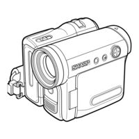
Sharp VL-Z500E-TVL-Z500E-S Service Manual (137 pages)
LIQUID CRYSTAL DISPLAY CAMCORDER
Brand:
Sharp
| Category:
Camcorder
| Size: 14.73 MB
Table of Contents
Table of Contents
1
AC Adapter (UADP-A053TAZZ)
2
Specifications
2
Front View
3
Left View
3
Part Names
3
Disassembly of the Set
4
Procedure for Disassembling the Cabinet
4
How to Make Mechanism Checking and Adjusting Jigs
8
Mechanism Adjustment Jigs and Parts
8
Parts for Periodic Inspection and Maintenance
8
Cautions in Handling the Mechanism
9
Inspection and Maintenance Items and Intervals
9
Maintenance and Inspection List
9
Adjusting and Checking of Mechanism
10
Checking of Height of Reel Table
10
Checking of PB (REC) Winding Torque
10
Checking of VS-REW Winding Torque
10
Checking and Adjusting of REC (PB) Back Tension Torque
11
Checking and Adjusting of Tension Pole Position During REC (PB)
11
Checking of S Reel Table Unloaded Torque
11
Checking of Loading Back Tension
12
Checking of Pinch Roller Press Force
12
Checking of VS-REW Back Tension
12
Adjustment of Height of Running System
13
Adjustment of Running System
13
Outline of Adjustment of Running System
13
Preparations for Adjustment of Running System
13
Adjustment of Height of Su and Tu Guide Rollers
14
Checking for Wrinkles in Tape
14
Checking of V/SR Envelope Waveform
14
Coarse Adjustment of Running System
14
Assembling of Mechanism Section and Part Replacement (Disassembling and Assembling)
15
Ejection Mode
15
Mechanism Mode
15
Standby Mode
15
Cassette Controller Assembly
16
Phase-Adjust
18
Assembling Method
19
Method of Assembling the Main Chassis Assembly
19
Method of Assembling the Slide Chassis Assembly
20
Method of Combining Main Chassis Assembly and Slide Chassis Assembly
21
Diagram of Greasing/Oiling Locations
22
Method of Installing the Cassette Controller
23
Method of Taking out the Cassette with the Mechanism Operating Singly
24
Adjustment of Liquid Crystal Video Section
25
Before Making Adjustment
25
List of Measuring Jigs
25
Method of Adjusting the Electric Circuit
25
VL-Z400S-T/H-T/Z500S-S/H-S/E-T/E-S Service Jig Configuration
26
Test Point
27
Wiring Board Diagram: Main Side a
27
Wiring Board Diagram: Sub Side a
28
Adjustment of Servo and System Controller
29
Automatic Adjustment
29
Execution of Adjustment
29
System Code Setting
29
Adjustment of Video I/O Circuit System
30
PCO D/A-C Adjustment
30
PCO D/A-Y Adjustment
30
Adjustment of Vf Circuit
31
Adjustment of VF_COM Amplitude (Main PWB)
31
Adjustment of VF_DAC Full Scale (Main PWB)
32
Adjustment of VF_WB (Main PWB)
32
Adjustment of COM-Bias (with the Unit Settings Complete)
33
Adjustment of DAC Full Scale (Main PWB)
33
Adjustment of Lcd Circuit
33
Adjustment of W/B (with the Unit Settings Complete)
33
Adjustment of MIC Amp Circuit
34
Checking of EE Level (Sub PWB)
34
Checking of F Characteristics (Sub PWB)
34
Setting of MODEL ID
34
DV Interface (Ieee1394) ID Setting
35
ID Code Application
35
Adjustment of Camera Section
37
List of Camera Jigs
37
Servicing of Camera Section
37
After Completion of Adjustment
38
Auto Focus Adjustment Mode
38
Camera Section Adjustment Mode
38
Description of Remote Control Keys
38
Camera Adjusting Procedure
39
Camera Signal System Adjustment Mode
39
Adjustment of Auto Focus
40
Adjustment of Black Balance/Adjustment of A/F Noise
40
Basic Adjustment of Iris
40
Rough Adjustment of Color Gain
41
Rough Adjustment of Iris AE
41
Rough Adjustment of White Balance
41
Adjustment of Auto White Balance
42
Adjustment of Color Gain
42
Adjustment of Iris AE
42
Adjustment of White Balance
42
Parameter List for Servicing Z500S
43
Camera (EE Mode)
44
Camera (REC Mode)
44
Useful Tips
44
VCR (EE Mode)
44
Ee Mode Flow (Video)
45
Flow in Rec Mode (Video)
45
Signal Flow Diagrams
45
Waveform Diagram
45
Flow in Pb Mode (Video)
46
Flow in Rec Mode (Audio)
46
Flow in Pb Mode (Audio)
47
Block Diagrams
48
System Block Diagram
48
Camera Section Block Diagram
49
Vio Engine Section Block Diagram (Vl-Z400)
50
Vio Engine Section Block Diagram (Vl-Z500)
51
Rec/Pb Section Block Diagram
52
Audio/Digital Output Section Block Diagram
53
Camera Circuit Block Diagram
54
Schematic Diagrams
56
Rec/Pb Engine Schematic Diagram (Vl-Z400)
57
Rec/Pb Engine Schematic Diagram (Vl-Z500)
58
MEC/SYS Micon SCHEMATIC DIAGRAM
59
Power1 Schematic Diagram
60
Camera Conn Schematic Diagram(Vl-Z400)
61
Camera Conn Schematic Diagram(Vl-Z500)
62
Video I/O Schematic Diagram (Vl-Z400)
63
Video I/O Schematic Diagram (Vl-Z500)
64
Lcdif Schematic Diagram
65
Connection(B-B) Schematic Diagram
66
Eq/Pll Schematic Diagram
67
CAM/CARD Micon SCHEMATIC DIAGRAM
68
Camera Video I/O Engine Schematic Diagram (Vl-Z400)
69
Camera Video I/O Engine Schematic Diagram (Vl-Z500)
70
Dac Schematic Diagram
71
Vfif Schematic Diagram
72
CCD Schematic Diagram
73
Tg Schematic Diagram
74
Cds Schematic Diagram
75
Lconn Schematic Diagram
76
Ext Dac Schematic Diagram
77
Lens Schematic Diagram
78
Audio I/O Schematic Diagram (Vl-Z400)
79
Audio I/O Schematic Diagram (Vl-Z500)
80
Power2 Schematic Diagram
81
MIC AMP SCHEMATIC DIAGRAM
82
Lcd Schematic Diagram
83
Inverter Schematic Diagram
84
Head Amp Schematic Diagram
85
Motor Drive Schematic Diagram
86
Operation Schematic Diagram
87
Lithium Schematic Diagram
88
Vcr Operation Schematic Diagram
89
Zoom Sw Schematic Diagram
90
Inner Led Schematic Diagram
91
Mecha Reversion Detection Schematic Diagram
92
Hole Sensor Unit Schematic Diagram
93
Semiconductor Lead Identification
94
Main Pwb
96
Printed Wiring Board Assemblies
96
CCD Pwb
98
Head Amp Pwb
103
Operation Pwb
104
Lithium Pwb
105
Mecha Reversion Detection Pwb
106
Vcr Operation Pwb
107
Zoom Sw Pwb
108
INNER LED PWB (VL-Z500 Only)
109
Electrical Parts List
111
Exploded Views
111
Integrated Circuits
111
Printed Wiring Board Assemblies
111
Replacement Parts List
111
CCD Pwb Unit
118
Mechanism Chassis Exploded View
129
Cabinet Exploded View
130
Cabinet Mechanism Exploded View
131
Cassette Control Explood View
132
Lens Unit Explood View
132
Adjusting Jigs for Checking the Mechanism
133
Parts for Periodical Inspection and Maintenance
133
Accessories
134
Accessories (Not Replacement Item)
134
Packing of the Set
134
Packing Parts (Not Replacement Item)
134
Packing of the Set (Vl-Z500)
135
Advertisement
Advertisement
Related Products
Sharp ViewcamZ VL-Z500E-T
Sharp VL-Z501D
Sharp VL-Z500E S
Sharp VL-Z500H
Sharp VL-Z500S
Sharp VL-Z500S-S
Sharp ViewcamZ VL-Z500H-S
Sharp ViewcamZ VL-Z500S-E
Sharp ViewcamZ VL-Z500E-S
Sharp VIEWCAMZ VL-Z5E
Sharp Categories
Microwave Oven
LCD TV
TV
Stereo System
All in One Printer
More Sharp Manuals
Login
Sign In
OR
Sign in with Facebook
Sign in with Google
Upload manual
Upload from disk
Upload from URL