Table of Contents
Advertisement
Available languages
Available languages
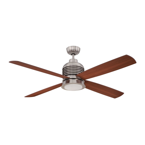
Metron
Installation Guide
For Model:
MET56BNK4
net weight of fan: 17.46 lb (7.92 kg)
READ THESE INSTRUCTIONS AND
SAVE THEM FOR FUTURE USE
Table of Contents:
Safety Tips. pg. 1
Unpacking Your Fan. pg. 2
Parts Inventory. pg. 2
Installation Preparation. pg. 3
Hanging Bracket Installation. pg. 3
Fan Assembly. pgs. 4 - 5
Wiring. pg. 6
Canopy Assembly. pg. 7
Blade Assembly. pg. 7
Light Kit Assembly. pg. 8
Learning Process. pgs. 9 - 10
Testing Your Fan. pg. 10
Troubleshooting. pg. 11
Warranty. pg. 11
Parts Replacement. pg. 11
PRINTED IN CHINA
Advertisement
Chapters
Table of Contents

Related Manuals for Ellington Metron MET56BNK4


Summary of Contents for Ellington Metron MET56BNK4
-
Page 1: Table Of Contents
READ THESE INSTRUCTIONS AND SAVE THEM FOR FUTURE USE Metron Installation Guide For Model: MET56BNK4 Table of Contents: Safety Tips. pg. 1 Unpacking Your Fan. pg. 2 Parts Inventory. pg. 2 Installation Preparation. pg. 3 Hanging Bracket Installation. pg. 3 Fan Assembly. -
Page 2: Safety Tips
SAFETY TIPS. WARNING: To reduce the risk of electrical shock, turn off the electricity to the fan at the main fuse box or circuit panel before you begin the fan installation or before servicing the fan or installing accessories. READ ALL INSTRUCTIONS AND SAFETY INFORMATION CAREFULLY BEFORE INSTALLING YOUR FAN AND SAVE THESE INSTRUCTIONS. -
Page 3: Unpacking Your Fan
1. Unpacking Your Fan. Carefully open the packaging. Remove items from Styrofoam inserts. Remove motor housing and place on carpet or Styrofoam to avoid damage to finish. Do not discard fan carton or Styrofoam inserts should this fan need to be returned for repairs. -
Page 4: Installation Preparation
3. Installation Preparation. blade edge To prevent personal injury and damage, ensure inches 7 feet that the hanging location allows the blades a (2.13 m) (76 cm) clearance of 7 feet (2.13m) from the floor and 30in. (76cm) from any wall or obstruction. This fan is suitable for room sizes up to 400 square 12ft. -
Page 5: Fan Assembly. Pgs
5. Fan Assembly. set screw Remove hanging ball from downrod provided by stop pin loosening set screw on hanging ball. Lower hanging ball and remove stop pin and then slide hanging ball hanging ball off of the downrod. [Refer to diagram 1.] diagram 1 Loosen yoke set screws and nuts at top of motor... - Page 6 5. Fan Assembly. (cont.) Thread safety cable and wires through hanging ball; then slide hanging ball over downrod--the top of the downrod should be noted as having a set screw hole; use this hole when setting the set screw. Insert stop pin into top of downrod and raise hanging ball.
-
Page 7: Wiring
6. Wiring. white supply wire CAUTION: Be sure outlet box is properly grounded or ground that a ground wire (GREEN or Bare) is present. (green or bare) black supply wire Make sure all electrical connections comply with Local Codes or Ordinances and the National Electrical Code. If you are unfamiliar with electrical wiring or if the from ceiling wire... -
Page 8: Canopy Assembly
7. Canopy Assembly. Locate 2 screws on underside of hanging bracket hanging bracket and remove screw closest to the open end of the hanging bracket. Partially loosen the other screw. Lift canopy to hanging bracket. Place rounded screw part of slotted hole in canopy over loosened screw in hanging bracket and push up. -
Page 9: Light Kit Assembly
9. Light Kit Assembly. Remove 1 screw from fitter plate on underside of motor and partially loosen the other 2 screws, save screws to attach LED light kit. Connect WHITE wire from motor housing to WHITE wire from light kit fitter. Connect BLACK wire from motor housing to BLACK wire from motor plate male plug... -
Page 10: Remote Control Assembly./Automated Learning Process. Pgs
10. Remote Control Assembly./Automated Learning Process. remote Gently pull on remote control cover to separate control top and bottom parts. [Refer to diagram 1.] cover In order to use wall control as a handheld remote control, cut each wire on wall control (that was not previously used)--use wire cutters to cut off each wire as close to the wall control as possible. -
Page 11: Testing Your Fan
10. Remote Control Assembly./Automated Learning Process. wall control remote control IMPORTANT: Remote and wall controls must be III IV SYNCHRONIZED with fan in order to properly function. Fan SPEED control buttons1: Use to control the ceiling fan speed 1-6 Fan OFF button 2: Use to turn the fan off REVERSE function button 3: Use to control fan direction... -
Page 12: Troubleshooting
Return fan, shipping prepaid, to transmitter and wall control are set properly. Craftmade/Ellington. We will repair or ship you a 3. Verify that wall control is wired properly. replacement fan, and we will pay the return shipping cost. - Page 13 LEER ESTAS INSTRUCCIONES Y GUARDARLAS PARA UTILIZACION FUTURA Metron Guía de instalación Para modelo: MET56BNK4 Indice de materias: Sugerencias de seguridad. Pág. 1 Desempaquetado del ventilador. Pág. 2 Inventario de piezas. Pág. 2 Preparación para la instalación. Pág. 3 Instalación del soporte de montaje. Pág. 3 Ensamblaje del ventilador.
-
Page 14: Sugerencias De Seguridad. Pág
SUGERENCIAS DE SEGURIDAD. ADVERTENCIA: Para evitar la posibilidad de una descarga eléctrica, desconectar la corriente en la caja de fusibles principal o el interruptor protector antes de iniciar la instalación del ventilador o antes de repararlo o instalar accesorios. LEER TODAS LAS INSTRUCCIONES E INFORMACION DE SEGURIDAD CUIDADOSAMENTE ANTES DE INSTALAR SU VENTILADOR Y GUARDAR ESTAS INSTRUCCIONES. -
Page 15: Desempaquetado Del Ventilador. Pág
1. Desempaquetado del ventilador. Abrir el empaque cuidadosamente. Sacar los artículos del embalaje. Sacar el motor y ponerlo en una alfombra o en el embalaje para evitar rayar el acabado. Guardar la caja de cartón o el empaquetamiento original en caso de que tenga que mandar el ventilador para alguna reparación. -
Page 16: Preparación Para La Instalación. Pág
3. Preparación para la instalación. Para prevenir daño corporal y otros daños, estar seguro borde del aspa de que el lugar en donde va a colgar el ventilador le 76 cm permite un espacio libre de 2,13 m (7 pies) entre las puntas de las aspas y el piso y 76 cm (30 pulg.) entre las 2,13 m pulg.) -
Page 17: Ensamblaje Del Ventilador. Págs
5. Ensamblaje del ventilador. tornillo de fijación perno Quitar la bola que sirve para colgar del tubo de tope provisto aflojando el tornillo de fijación de la bola que sirve para colgar. Bajar la bola que sirve para colgar y sacar el perno de tope y luego bola que quitar la bola que sirve para colgar deslizándola. - Page 18 5. Ensamblaje del ventilador. (cont.) Pasar los cables y el cable de seguridad por la bola que sirve para colgar; luego deslizar la bola que sirve para colgar sobre el tubo--la parte de arriba del tubo debe tener el agujero para el tornillo de fijación en ese extremo;...
-
Page 19: Instalación Eléctrica. Pág
6. Instalación eléctrica. PRECAUCION: Asegurarse de que la caja de salida esté alambre conductor blanco conectada a tierra como es debido o que exista un toma de tierra conductor a tierra (VERDE o pelado). (verde o pelada) alambre conductor negro Asegurarse de que toda conexión eléctrica cumpla con los Códigos o las Ordenanzas Locales y el Código Nacional Eléctrico. -
Page 20: Colocación De La Cubierta Decorativa. Pág
7. Colocación de la cubierta decorativa. Localizar los 2 tornillos en la parte inferior del soporte de soporte de montaje y quitar el tornillo que está montaje localizado más cerca del extremo abierto del soporte de montaje. Aflojar parcialmente el otro tornillo tornillo. -
Page 21: Instalación Del Juego De Luz. Pág
9. Instalación del juego de luz. Quitar 1 tornillo de la placa de conexión y parcialmente aflojar los otros 2 tornillos, guardarlos para fijar el juego de luz LED más adelante. enchufe Quitar 1 tornillo de la placa del motor en el lado placa del macho motor... -
Page 22: Ensamblaje Del Control Remoto./Proceso De
10. Ensamblaje del control remoto./Proceso de aprendizaje automático. cubierta del control remoto Con cuidado separar la cubierta del control remoto, despegando la parte superior de la inferior. [Referirse al diagrama 1.] Para utilizar el control de pared como control remoto de mano, cortar cada cable en el control de pared (que no se usó... - Page 23 10. Ensamblaje del control remoto./Proceso de aprendizaje automático. control de pared control remoto IMPORTANTE: Hay que SINCRONIZAR III IV el control remoto y el control de pared con el ventilador para que funcionen correctamente. Botones de VELOCIDAD del ventilador 1: usar para controlar la velocidad del ventilador de 1- 6 Botón de APAGADO 2: usar para apagar el ventilador Botón de REVERSA 3:...
- Page 24 1. Inspeccionar el interruptor de pared del ventilador. Craftmade/Ellington pagará los gastos de envío de regreso. 2. Verificar que se hizo correctamente la conexión de GARANTIA LIMITADA DE 6 AÑOS hasta DE POR VIDA: cables en la cubierta decorativa.
Need help?
Do you have a question about the Metron MET56BNK4 and is the answer not in the manual?
Questions and answers