Table of Contents
Advertisement
Quick Links
Download this manual
See also:
User Manual
Advertisement
Table of Contents

Related Manuals for Honeywell ST 800


Summary of Contents for Honeywell ST 800
- Page 1 ST 800 SmartLine Pressure Transmitters User’s Manual 34-ST-25-35 Revision 10.0 July 2016 Honeywell Process Solutions...
- Page 2 In no event is Honeywell liable to anyone for any indirect, special, or consequential damages. The information and specifications in this document are subject to change without notice.
- Page 3 Honeywell’s family of ST 800 SmartLine Pressure Transmitters. Users who have a Honeywell ST 800 SmartLine Pressure Transmitter configured for HART protocol or Honeywell’s Digitally Enhanced (DE) are referred to the ST 800 Series HART/DE Option User’s Manual, document number 34-ST-25-38. Users who have a Honeywell ST 800 SmartLine Pressure Transmitter configured for Fieldbus operation are referred to the ST 800 Series Fieldbus Option User’s Manual, document number (34-ST-25-39).
- Page 4 Smart Field Communicator Model STS 103 Operating Guide, Document # 34-ST-11-14 Patent Notice The Honeywell ST 800 SmartLine Pressure Transmitter family is covered by one or more of the following U. S. Patents: 5,485,753; 5,811,690; 6,041,659; 6,055,633; 7,786,878; 8,073,098; and other patents pending.
- Page 5 Chassis Ground: Identifies a connection to the chassis or frame of the equipment shall be bonded to Protective Earth at the source of supply in accordance with national and local electrical code requirements. continued ST 800 SmartLine Pressure Transmitters User’s Manual Revision 10 Page v...
- Page 6 The Ex mark means the equipment complies with the requirements of the European standards that are harmonised with the 94/9/EC Directive (ATEX Directive, named after the French "ATmosphere EXplosible"). ST 800 SmartLine Pressure Transmitters User’s Manual Page vi Revision 10...
-
Page 7: Table Of Contents
Plugged Impulse Line detection (PILD) ................. 6 Installation and Startup ........................7 Installation Site Evaluation ..................... 7 Honeywell MC Toolkit......................7 Display Installation Precautions ..................... 7 Mounting ST 800 SmartLine Pressure Transmitters .............. 8 3.4.1 Summary......................... 8 3.4.2 Mounting Dimensions ....................8 3.4.3... - Page 8 A2. European Directive Information (CE Mark) ................92 A3. Hazardous Locations Certifications ..................98 A4. Control Drawing ........................102 A5. Marine Approvals ........................106 A6. Measurement Instruments Directive (MID) ................106 Glossary ............................. 108 ST 800 SmartLine Pressure Transmitters User’s Manual Page viii Revision 10...
- Page 9 Figure 31 – Electronic Housing, Terminal Block End ................. 76 Figure 32 – Transmitter Major Assemblies ..................78 Figure 33 - ST 800 Models STD810, 820, 830, & 870 ................ 81 Figure 34 – STG830, 840, 870, and STA822, 840 Transmitter Body ..........84 Figure 35 –...
- Page 10 Table 23 – Transmitter Major Assemblies ................... 76 Table 24 – ST 800 Models STD810, 820, 830 & 870 (Ref. Figure 33)..........80 Table 25 – Parts for STG830, 840, 870 and STA822, 840 Transmitter Body (Ref. ) ......83 Table 26 –...
-
Page 11: Introduction
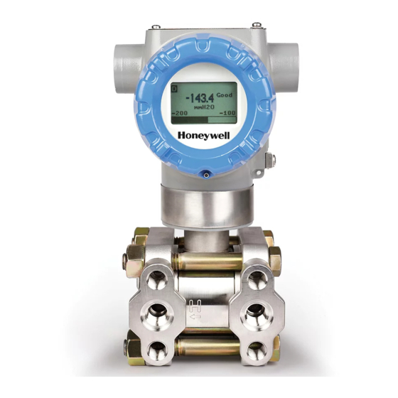
Plugged Impulse Line Detection (PILD) 1.2.1 Physical Characteristics As shown in Figure 1, the ST 800 is packaged in two major assemblies: the Electronics Housing and the Meter Body. The elements in the Electronic Housing respond to setup commands and execute the software and protocol for the different pressure measurement types. -
Page 12: Functional Characteristics
Honeywell Multi-Communication (MC) Toolkit (not supplied with the Transmitter) can facilitate setup and adjustment procedures. Certain adjustments can be made through an Experion Station or a Universal Station if the Transmitter is digitally integrated with Honeywell’s Experion or TPS/TDC 3000 control system. -
Page 13: St 800 Transmitter Name Plate
1.5 Transmitter Adjustments Zero and Span adjustments are possible in ST 800 SmartLine Pressure Transmitters with the optional three-button assembly located at the top of the Electronic Housing (see Figure 2). You can also use the Honeywell MC Toolkit or other third-party hand-held zero to make any adjustments to an ST 800 SmartLine Pressure Transmitter. -
Page 14: Display Options
1.6 Display Options The ST 800 SmartLine Pressure Transmitter has two display options: Basic and Advanced; see Error! Reference ource not found.. Table 2 – Available Display Characteristics Basic Display Suitable for basic process needs rotation in 90 Increments ... -
Page 15: Application Design
2 Application Design 2.1 Overview This section discusses the considerations involved with deploying a Honeywell ST 800 SmartLine Pressure Transmitter in a process system. The following areas are covered: Safety Input and output data Reliability Environmental limits ... -
Page 16: Safety Integrity Level (Sil)
A Safety Instrumented Function (SIF) designed with this product must not be used at a SIL level higher than the statement, without “prior use” justification by the end user or diverse technology redundancy in the design. Refer to the ST 800 & ST 700 Safety Manual, 34-ST-25-37, for additional information. -
Page 17: Installation And Startup
3 Installation and Startup 3.1 Installation Site Evaluation Evaluate the site selected for the ST 800 Transmitter installation with respect to the process system design specifications and Honeywell’s published performance characteristics for your particular model. Some parameters that you may want to include in your site evaluation are: ... -
Page 18: Mounting St 800 Smartline Pressure Transmitters
Transmitter models, except flush mounts and those with integral flanges, can be attached to a two- inch (50 millimeter) vertical or horizontal pipe using Honeywell’s optional angle or flat mounting bracket; alternately you can use your own bracket. Flush-mount models are attached directly to a process pipe or tank by a one-inch weld nipple. -
Page 19: Bracket Mounting Procedure
See the STAxxL) following example. Mounting holes in the end of the process Dual-head GP and AP head. EXAMPLE: Inline model mounted to an optional angle bracket. See Figure 6. ST 800 SmartLine Pressure Transmitters User’s Manual Revision 10 Page 9... -
Page 20: Figure 6 - Inline Model Mounted To An Optional Bracket
O) for a Draft Range Transmitter can result from a mounting position that is rotated from the vertical. A typical zero-shift of 0.12 mmHg or 0.20 inH O can occur for a five (5)-degree rotation from the vertical. ST 800 SmartLine Pressure Transmitters User’s Manual Page 10 Revision 10... -
Page 21: Mounting Transmitters With Small Absolute Or Differential Pressure Spans
Transmitter is vertical when mounting it. You do this by leveling the Transmitter side-to-side and front-to-back. Figure 8 shows how to level a Transmitter using a spirit level. Figure 8 – Using a Spirit Balance to Level a Transmitter ST 800 SmartLine Pressure Transmitters User’s Manual Revision 10 Page 11... -
Page 22: Flange Mounting
To prevent performance degradation in extended-mount flanged Transmitters, ensure that sufficient clearance exists in front of the sensing diaphragm body. Figure 9 – Tank-Flange Mounted Transmitter ST 800 SmartLine Pressure Transmitters User’s Manual Page 12 Revision 10... -
Page 23: Flush Mounting Procedure
3. Insert the Transmitter Meter Body into the mounting sleeve, and secure it with the locking bolt. 4. Tighten the bolt to a torque of 4 Nm +0.3 Nm (4.7 pound-feet +0.2 pound-feet). ST 800 SmartLine Pressure Transmitters User’s Manual Revision 10 Page 13... -
Page 24: Remote Diaphragm Seal Mounting Information
Figure 11 – Representative Remote Diaphragm Seal Transmitter Installation Depending on Transmitter model, connect the remote seal to the tank according to ST 800 SmartLine Pressure Transmitters User’s Manual Page 14 Revision 10... - Page 25 Table 5 ST 800 SmartLine Pressure Transmitters User’s Manual Revision 10 Page 15...
-
Page 26: Piping The St 800 Transmitter
To High Pr essure Side of Transmit ter Side of Transmit ter To W aste To W aste 210 10 Figure 12 – Typical 3-Valve Manifold with Blow-Down Piping ST 800 SmartLine Pressure Transmitters User’s Manual Page 16 Revision 10... - Page 27 ST 800 SmartLine Pressure Transmitters User’s Manual Revision 10 Page 17...
-
Page 28: Suggestions For Transmitter Location
NOTE: The threaded hole in each Flange Adapter is offset from center. To ensure proper orientation for re-assembly, note the orientation of the offset relative to each Process Head before removing any adapter. ST 800 SmartLine Pressure Transmitters User’s Manual Page 18 Revision 10... -
Page 29: Figure 13 - Flange Adapter Removal And Replacement
Figure 13 – Flange Adapter Removal and Replacement Refer to the instructions included with the kit for removal and replacement procedures. ST 800 SmartLine Pressure Transmitters User’s Manual Revision 10 Page 19... -
Page 30: Wiring A Transmitter
(+) and negative (–) terminals on the Transmitter terminal block in the Electronics Housing shown in Figure 15. Figure 15 – Transmitter 3-Screw Terminal Board and Grounding Screw ST 800 SmartLine Pressure Transmitters User’s Manual Page 20 Revision 10... -
Page 31: Digital System Integration Information
The positive and negative loop wires are connected to the positive (+) and negative (–) terminals on the terminal block in the Transmitter Electronics Housing. Barriers can be installed per Honeywell’s instructions for Transmitters to be used in intrinsically safe applications. -
Page 32: Wiring Variations
42 V DC. Consult the process design system documentation for specifics. 3.6.7 Process Sealing The ST 800 SmartLine Pressure Transmitter is CSA-certified as a Dual Seal device in accordance with ANSI/ISA–12.27.01–2003, “Requirements for Process Sealing Between Electrical Systems and Flammable, or Combustible Process Fluids.”... -
Page 33: Startup
The actual steps in a startup procedure vary based on the type of Transmitter and the measurement application. In general, the procedures in this section are based on using Honeywell MC Toolkit to check the Transmitter input and output under static process conditions, and make adjustments as required initiating full operation with the running process. -
Page 34: Constant Current Source Mode Procedure
8. To view the monitor display, navigate back from the LOOP TEST display, and select the MONITOR display. A Confirm popup will be displayed. 9. Select Yes to continue. This concludes the Startup procedure. ST 800 SmartLine Pressure Transmitters User’s Manual Page 24 Revision 10... -
Page 35: Operation
HART operation using the 3-button option. 4.2 Three-Button Operation The ST 800 optional three-button interface provides a user interface and operation capability without opening the transmitter. Figure 17 shows the location of the three-button option and the labels for each button. - Page 36 ST 800 SmartLine Pressure Transmitters User’s Manual Page 26 Revision 10...
-
Page 37: Menu Navigation
If no button presses occur within 60 seconds, menu access will time out and the transmitter will exit the menu and return to the PV display. ST 800 SmartLine Pressure Transmitters User’s Manual Revision 10 Page 27... -
Page 38: Data Entry
4. After the last digit has been entered, press one more time to write the new value to the transmitter. ST 800 SmartLine Pressure Transmitters User’s Manual Page 28 Revision 10... -
Page 39: Selecting A New Setting From A List Of Choices
Install date PILD (Optional)* Display Information Elec Module For details go to the Information Menu table. Meterbody *This feature is available only if ST 800 Sensor supports PILD feature. ST 800 SmartLine Pressure Transmitters User’s Manual Revision 10 Page 29... -
Page 40: Table 10 - Diagnostics Menu
The transmitter has not been calibrated Factory Cal NO FACTORY CAL by the factory. The DAC has not been compensated DAC Temp for temperature effects. This is a factory Comp NO COMPENSATION operation. ST 800 SmartLine Pressure Transmitters User’s Manual Page 30 Revision 10... - Page 41 NOTE: This diagnostics message or PILD sub menu will be visible only if PILD feature is supported by the sensor and user enabled in the PILD option in the transmitter. ST 800 SmartLine Pressure Transmitters User’s Manual Revision 10 Page 31...
-
Page 42: Table 11 - Display Setup Menus
to enter mmH2O @ 4 mmH2O @ 68 mmHg @ 0 C For calibration, this parameter Torr allows the user to match the value displayed on the menus to ST 800 SmartLine Pressure Transmitters User’s Manual Page 32 Revision 10... - Page 43 to enter and shift to Custom Square Root (only next char up to 8 char Units available for DP Display transmitters) gal/min Units gal/h See Note 2 below. ST 800 SmartLine Pressure Transmitters User’s Manual Revision 10 Page 33...
- Page 44 14 characters long. to enter and shift to next char. NOTES: Scaling only affects the value shown on the Display; it does not affect the Loop Output. ST 800 SmartLine Pressure Transmitters User’s Manual Page 34 Revision 10...
- Page 45 ST 800 SmartLine Pressure Transmitters User’s Manual Revision 10 Page 35...
- Page 46 Factor value is present only when PILD is enabled and while in Monitoring mode. Otherwise the value will be replaced by a message indicating PILD is disabled or in Training mode. ST 800 SmartLine Pressure Transmitters User’s Manual Page 36...
- Page 47 The trend format provides two dotted horizontal lines on the trend chart to indicate the Up Limit and Down Limit values. ST 800 SmartLine Pressure Transmitters User’s Manual Revision 10 Page 37...
-
Page 48: Table 12 - Calibration Menus
Press to enter menu Reset Executing this selection Resets the Zero, selection Corrects Reset Corrects LRV, and URV Corrects back to Factory Scroll to Reset Corrects values Press to initiate ST 800 SmartLine Pressure Transmitters User’s Manual Page 38 Revision 10... - Page 49 ST 800 SmartLine Pressure Transmitters User’s Manual Revision 10 Page 39...
- Page 50 Cal Set C** calibration type. menu, to initiate Best Fit NOTES: * "Cal Set B" item in menu is available only if sensor supports Dual calibration ST 800 SmartLine Pressure Transmitters User’s Manual Page 40 Revision 10...
-
Page 51: Table 13 - Transmitter Setup Menus
Dual Slope This item is only available when the Transfer Function is set to Square Root. Enter the low flow cutoff Breakpt(%Flow) ##. # point when Single Breakpt ST 800 SmartLine Pressure Transmitters User’s Manual Revision 10 Page 41... - Page 52 Range: 0 to 25.0 %Flow. ST 800 SmartLine Pressure Transmitters User’s Manual Page 42 Revision 10...
- Page 53 # # # # Select the current January thru Month month. December HART Date Enter the day of the month. Press ENTER to write the HART Date to the Write Date transmitter. ST 800 SmartLine Pressure Transmitters User’s Manual Revision 10 Page 43...
- Page 54 DP Flow (Available only selection for DP Transmitter) and to Marine Level Application See Note below. select Bubbler Level Application Type. to initiate. Other ST 800 SmartLine Pressure Transmitters User’s Manual Page 44 Revision 10...
- Page 55 This parameter will be “Read Only” when the user configures PILD as Enabled in this sub menu. An attempt to configure this parameter will then invoke the pop-up message”Read Only! PILD Active”. The parameters Up ST 800 SmartLine Pressure Transmitters User’s Manual Revision 10...
- Page 56 Limit, Down Limit and Both Limit are available to change in Monitoring mode while PILD is enabled. An attempt to change these parameters in Training mode results in the pop-up "Read Only! Training Mode". ST 800 SmartLine Pressure Transmitters User’s Manual Page 46...
-
Page 57: The Basic Display Menu
Menu. 1. Select <Exit Menu> and press to exit the Menu. 2. Use the and buttons to scroll through the list of menu items. ST 800 SmartLine Pressure Transmitters User’s Manual Revision 10 Page 47... -
Page 58: Table 15 - The Basic Display Menus
Enter Custom Tag using and and to select alphanumeric value up to 14 Custom Tag Alphanumeric characters long to enter and shift to next char. ST 800 SmartLine Pressure Transmitters User’s Manual Page 48 Revision 10... - Page 59 Do Correct the LRV based on the input initiate action pressure Executing this selection Resets Reset Corrects Do Correct the Zero, LRV, and URV Corrects back to Factory values ST 800 SmartLine Pressure Transmitters User’s Manual Revision 10 Page 49...
- Page 60 and to select NAMUR burnout levels to the Honeywell Disabled levels from list to enter Fast Speed of Response Filter Perf Fast SOR Standard Speed of Response Standard SOR ST 800 SmartLine Pressure Transmitters User’s Manual Page 50 Revision 10...
- Page 61 Transmitter. You cannot erase Read Only after or overwrite the Install Date once it entered has been written. ST 800 SmartLine Pressure Transmitters User’s Manual Revision 10 Page 51...
-
Page 62: Selecting A New Setting From A List Of Choices
Value of the transmitter. ↓ 3. Press the Down ( ) and Span ( ) buttons together to set the span. 4. Verify that the PV output is now 20 mA. ST 800 SmartLine Pressure Transmitters User’s Manual Page 52 Revision 10... - Page 63 You can also use the MCT 202 Toolkit to make any adjustments to an ST 800 SmartLine Pressure Transmitter. Alternately, certain adjustments are possible through an Experion Station or Universal Station, if the ST 800 is digitally integrated with either of these stations.
-
Page 64: Changing The Default Failsafe Direction
The following procedure outlines the steps for positioning the write protect and failsafe jumpers on the electronics module. See Figure 18 for the locations of the failsafe and write protect jumpers. ST 800 SmartLine Pressure Transmitters User’s Manual Page 54... -
Page 65: Figure 18 - Locating The Failsafe And Write Protect Jumpers
Write Protect = OFF (Not Protected) Failsafe = DOWN (Low) Write Protect = OFF (Not Protected) Failsafe = UP (High) Write Protect = ON (Protected) Failsafe = Down (Low) Write Protect = On (Protected) ST 800 SmartLine Pressure Transmitters User’s Manual Revision 10 Page 55... -
Page 66: Table 17 - Fieldbus Simulation And Write Protect Jumpers
Orient the Display for proper viewing through the end cap window. You can rotate the meter mounting orientation in 90 increments. 7. Restore transmitter power if removed. ST 800 SmartLine Pressure Transmitters User’s Manual Page 56 Revision 10... -
Page 67: Monitoring The Basic And Advanced Displays
PV Trend. User-configurable display period from one hour to 24 hours. The chart displays minimum, maximum, and average of the configured PV over the selected trend period. Figure 20 – Advanced Display Formats with the Process Variable ST 800 SmartLine Pressure Transmitters User’s Manual Revision 10 Page 57... -
Page 68: Table 18 - Advanced Displays With Pv Format Display Indications
PV Value will be displayed on a black background as shown below: Uncertain (this status is only available for FF transmitters) The PV Value is outside of normal limits. ST 800 SmartLine Pressure Transmitters User’s Manual Page 58 Revision 10... -
Page 69: Button Operation During Monitoring
( and ) can be used to move to the next or previous operator screen without waiting for the rotation time to expire. Pressing the Enter button ( ) will call up the Main Menu. ST 800 SmartLine Pressure Transmitters User’s Manual Revision 10 Page 59... -
Page 70: Maintenance
5.2 Preventive Maintenance Practices and Schedules The ST 800 Transmitter does not require any specific maintenance at regularly scheduled intervals. However, it is recommended that you perform these typical inspection and maintenance routines on a schedule that is dictated by the characteristics of the process medium and if blow-down facilities or purge systems are being used. -
Page 71: Figure 21 - Dp Transmitter Head Disassembly
8. Inspect the barrier diaphragm for signs of deterioration, corrosion, and distortion. 9. If the diaphragm is distorted contact Honeywell for assistance. 10. Install a new gasket/O-ring in each process head. 11. Coat threads on the process head bolts with a suitable anti-seize compound, such as “Neverseize,”... -
Page 72: Figure 22 - Head Bolt Tightening Sequence
Figure 22 – Head Bolt Tightening Sequence Table 19 – Head Bolt Torque Values ST 800 SmartLine Pressure Transmitters User’s Manual Page 62 Revision 10... -
Page 73: Replacing The Communication Module
Installing a Display Module into a powered transmitter may cause a temporary upset to the loop output value. 2. Loosen the end cap lock, and unscrew the end cap from the electronics side of the Transmitter housing. ST 800 SmartLine Pressure Transmitters User’s Manual Revision 10 Page 63... - Page 74 (Steps 13 - 16 required for Field Upgrades Only) 13. Loosen the End Cap locking screw and unscrew the End Cap from the Field Wiring side of the transmitter housing. ST 800 SmartLine Pressure Transmitters User’s Manual Page 64 Revision 10...
-
Page 75: Replacing The Meter Body
18. Check the settings of the Transmitter Setup and Display Setup parameters to make sure that the transmitter is configured correctly for your application. See the HART and DE User's Manual (ST 800 #34-ST-25-38, ST 700 #34-ST-25-47) for details on HART and DE transmitters. Refer to manual #34-ST-25-39 for additional information about Fieldbus transmitters. -
Page 76: Figure 25 - Hardware Location To Remove The Meter Assembly
O-rings to the meter body. If installing O-rings, lubricate with water or leave dry. 14. Coat threads on process head bolts with anti-seize compound such as “Neverseize” or equivalent. ST 800 SmartLine Pressure Transmitters User’s Manual Page 66 Revision 10... -
Page 77: Figure 26 - Meter Body Reassembly
Body to the electronics housing. 18. Screw the new meter body into the housing until the bottom of the Meter Body adapter is flush with the neck of the electronics housing. ST 800 SmartLine Pressure Transmitters User’s Manual Revision 10 Page 67... -
Page 78: Pild Option Licensing
Reference document PILD Upgrade Option, ST 800 Instruction (#34-ST-33-73) for firmware revision level requirements. Place an order for PILD Field Upgrade for ST 800, part number 50097038-501 with the Serial Number. Based on this information the regional distribution centre will generate and return a license key. -
Page 79: Calibration
For a Transmitter operating in analog mode, you must calibrate its output signal measurement range using any compatible hand-held communicator or a local display. One calibration option is to use the Honeywell Smart Field Communicator (SFC). Refer to the Smart Field Communicator Operating Guide, 34-ST-11-14 for calibration procedures. - Page 80 ST 800 SmartLine Pressure Transmitters User’s Manual Page 70 Revision 10...
-
Page 81: Troubleshooting
However, this section covers the diagnostic messages that indicate critical conditions. Other than the critical conditions, additional detail is not provided. If you require assistance, contact your distributor or Honeywell Technical Support. All other messages are covered by the MC Toolkit Users’ Manual. 7.2 Critical Diagnostics Screens When a Critical Diagnostic is present in the Transmitter, the Advanced Display will show one or more of the screens pictured in Figure 28. - Page 82 Cycle power to the transmitter. If the problem continues to occur replace the Electronics Module. If this does not fix the problem, replace the Meterbody. ST 800 SmartLine Pressure Transmitters User’s Manual Page 72 Revision 10...
-
Page 83: Parts List
Gasket only, Process Head (6 Viton Head O- Figure 33 & Rings) 6-12 12-24 Figure 34 51452868-507 Gasket only, Process Head Graphite Gasket 6-12 12-24 (replacement only for existing graphite gasket) ST 800 SmartLine Pressure Transmitters User’s Manual Revision 10 Page 73... -
Page 84: Figure 29 - Angle And Flat Bracket Parts
LGP/LAP Models Figure 35 nameplate Flush Mount Models Figure 36 Flange Mount Models Figure 37 Remote Diaphragm Seal Models Figure 39 Figure 29 – Angle and Flat Bracket Parts ST 800 SmartLine Pressure Transmitters User’s Manual Page 74 Revision 10... -
Page 85: Figure 30 - Electronic Housing, Display End
51196557-008 SS 316 Flat Bracket Mounting kit for all In-line transmitters except In-Line and Flush mount transmitters 51196557-009 SS 316 Flat Bracket Mounting kit for all In-Line and Flush mount transmitters Figure 30 – Electronic Housing, Display End ST 800 SmartLine Pressure Transmitters User’s Manual Revision 10 Page 75... -
Page 86: Figure 31 - Electronic Housing, Terminal Block End
FF Electronics Module Assembly (PWA) with Reed sensor 50049915-501 External Zero, Span & Config Buttons 30757503-005 Electronics housing seals kit (includes O-rings) Figure 31 – Electronic Housing, Terminal Block End ST 800 SmartLine Pressure Transmitters User’s Manual Page 76 Revision 10... - Page 87 ST 800 SmartLine Pressure Transmitters User’s Manual Revision 10 Page 77...
-
Page 88: Figure 32 - Transmitter Major Assemblies
Figure 32 – Transmitter Major Assemblies ST 800 SmartLine Pressure Transmitters User’s Manual Page 78 Revision 10... - Page 89 ST 800 SmartLine Pressure Transmitters User’s Manual Revision 10 Page 79...
-
Page 90: Table 24 - St 800 Models Std810, 820, 830 & 870 (Ref. Figure 33)
Table 24 – ST 800 Models STD810, 820, 825, 830 & 870 (Ref. Figure 33) Part Number Description Qty/Unit Vent and Plug Kits 30753785-001 Drain and Plug Kit, stainless steel 30753787-001 Drain and Plug Kit, Monel 30753786-001 Drain and Plug Kit, Hastelloy C... -
Page 91: Figure 33 - St 800 Models Std810, 820, 830, & 870
Figure 33 - ST 800 Models STD810, 820, 825, 830, & 870 ST 800 SmartLine Pressure Transmitters User’s Manual Revision 10 Page 81... - Page 92 ST 800 SmartLine Pressure Transmitters User’s Manual Page 82 Revision 10...
-
Page 93: Table 25 - Parts For Stg830, 840, 870 And Sta822, 840 Transmitter Body (Ref. )
Note 2: The Kit for Process Heads without side vent/drain does not include Pipe Plugs (K1). Reference Head 51452951-201 Carbon Steel Blind Reference Head 51452951-101 316 SS Blind Reference Head ST 800 SmartLine Pressure Transmitters User’s Manual Revision 10 Page 83... -
Page 94: Figure 34 - Stg830, 840, 870, And Sta822, 840 Transmitter Body
Figure 34 – STG830, 840, 870, and STA822, 840 Transmitter Body ST 800 SmartLine Pressure Transmitters User’s Manual Page 84 Revision 10... - Page 95 ST 800 SmartLine Pressure Transmitters User’s Manual Revision 10 Page 85...
-
Page 96: Figure 35 - Inline Gauge And Inline Atmospheric Display Bodies
Part Number Description Qty/Unit Specify complete model Replacement meter body (Flush Mount model) number from nameplate 30756445-508 Gasket Kit (0-rings) 51204496-001 316L SS Mounting Sleeve Kit 51204497-001 Calibration Sleeve Kit ST 800 SmartLine Pressure Transmitters User’s Manual Page 86 Revision 10... -
Page 97: Figure 36 - Flush Mount Meter Body
Flange adapter kit (Hastelloy C flange adapter with 316 st. 30754419-023 steel bolts) Bolt, hex head, 7/16-20 UNF, 1.375 inches lg. Flange adapter Gasket Housing seal kit 30757503-005 ST 800 SmartLine Pressure Transmitters User’s Manual Revision 10 Page 87... -
Page 98: Figure 37 - Extended Flange Design
Figure 37 – Extended Flange Design Figure 37b – Flush Flange Design ST 800 SmartLine Pressure Transmitters User’s Manual Page 88 Revision 10... -
Page 99: Figure 38 - Pseudo Flange Design
Figure 38 - Pseudo Flange design Figure 39 – Remote Seal Diaphragm No replacement meter body (Key No.1) is available for Remote Diaphragm Seal models ST 800 SmartLine Pressure Transmitters User’s Manual Revision 10 Page 89... - Page 100 ST 800 SmartLine Pressure Transmitters User’s Manual Page 90 Revision 10...
-
Page 101: Figure 40 - Coplanar Adapter Replacement Seals Kit
50062206-007 - O-rings removed from service should be discarded and replaced with new o- rings. Do not use o-rings with nicks or other signs of damage. Figure 40 - COPLANAR ADAPTER REPLACEMENT SEALS KIT ST 800 SmartLine Pressure Transmitters User’s Manual Revision 10 Page 91... -
Page 102: Appendix A. Product Certifications
Appendix A. PRODUCT CERTIFICATIONS A1. Safety Instrumented Systems (SIS) Installations For Safety Certified Installations, please refer to ST 800 & ST 700 Safety Manual 34-ST-25-37 for installation procedure and system requirements. SIL 2/3 IEC 61508 SIL 2 for non-redundant use and SIL 3 for redundant use according to EXIDA, ST800 Certification Series, HON 1002038 C001, ST 700 Series HON 1207125 C001 and TÜV Nord Sys Tec GmbH &... - Page 103 ST 800 SmartLine Pressure Transmitters User’s Manual Revision 10 Page 93...
- Page 104 ST 800 SmartLine Pressure Transmitters User’s Manual Page 94 Revision 10...
- Page 105 ST 800 SmartLine Pressure Transmitters User’s Manual Revision 10 Page 95...
- Page 106 ST 800 SmartLine Pressure Transmitters User’s Manual Page 96 Revision 10...
- Page 107 ST 800 SmartLine Pressure Transmitters User’s Manual Revision 10 Page 97...
-
Page 108: A3. Hazardous Locations Certifications
60079-11: 2002; ANSI/ ISA 60079-26 : 2008; ANSI/ ISA 12.12.01 : 2007 ; ANSI/ ISA 60079-15 : 2009 ; C22.2 No. 213-M1987; CAN/CSA-E60079-15: 2002; ANSI/ UL 50 : 2007 ; ANSI/ IEC 60529 : 2004 ST 800 SmartLine Pressure Transmitters User’s Manual Page 98... - Page 109 (South Ex nA IIC Gc Africa) Flameproof: DE/HART Ex d IIC Ga/Gb Note 1 T4: -50 C to 85 Ex tb IIIC T 95 C Db Enclosure: IP66/ IP67 ST 800 SmartLine Pressure Transmitters User’s Manual Revision 10 Page 99...
- Page 110 (02) and the second two digits identify the week of the year (23); for example, 0223xxxxxxxx indicates that the product was manufactured in 2002, in the 23 rd week. ST 800 SmartLine Pressure Transmitters User’s Manual Page 100...
- Page 111 IIC gases. Therefore, the user/ installer shall implement precautions to prevent the buildup of electrostatic charge, e.g. earthing the metallic part. This is particularly important if equipment is installed a Zone 0 location. ST 800 SmartLine Pressure Transmitters User’s Manual Revision 10 Page 101...
-
Page 112: A4. Control Drawing
A4. Control Drawing ST 800 SmartLine Pressure Transmitters User’s Manual Page 102 Revision 10... - Page 113 ST 800 SmartLine Pressure Transmitters User’s Manual Revision 10 Page 103...
- Page 114 ST 800 SmartLine Pressure Transmitters User’s Manual Page 104 Revision 10...
- Page 115 ST 800 SmartLine Pressure Transmitters User’s Manual Revision 10 Page 105...
-
Page 116: A5. Marine Approvals
0 to 7 Bar STA84L 0 to 35 Bar A STG84L 0 to 35 Bar STD870 0 to 100 Bar STA87L 0 to 100 Bar A STG87L 0 to 100 Bar ST 800 SmartLine Pressure Transmitters User’s Manual Page 106 Revision 10... - Page 117 ST 800 SmartLine Pressure Transmitters User’s Manual Revision 10 Page 107...
-
Page 118: Glossary
Smart Field Communicator STIM Pressure Transmitter Interface Module STIMV IOP Pressure Transmitter Interface Multivariable Input/Output Processor Thermocouple Upper Range Limit Upper Range Value Universal Station Volts Alternating Current Volts Direct Current ST 800 SmartLine Pressure Transmitters User’s Manual Page 108 Revision 10... - Page 119 Application Design ........5 Installation and Startup .......7 Display Installation Precautions ........ 7 Basic Display Menus ........40 Mounting ST 800 SmartLine Pressure Transmitters .. 7 Bracket Mounting ........9 Site evaluation ............7 Button operation during monitoring ..50 Installation Site Evaluation Site Evaluation ............
- Page 120 Troubleshooting ........62 Patent Notice ..........iv Critical Diagnostics Screens ........62 PILD Option Licensing ........ 59 Piping the ST 800 Transmitter ....15 Piping Arrangements ..........15 Wiring a Transmitter ......... 18 Transmitter location ..........16 Plugged Impulse Line Detection ....6 Wiring Procedure ............
- Page 121 Phone: (86-21) 5257-4568 Fax: (86-21) 6237-2826 Singapore Honeywell Pte Ltd. Phone: +(65) 6580 3278 Fax: +(65) 6445-3033 South Korea Honeywell Korea Co Ltd Phone: +(822) 799 6114 Fax: +(822) 792 9015 ST 800 SmartLine Pressure Transmitters User’s Manual Revision 10 Page 111...
- Page 122 For more information To learn more about SmartLine Transmitters, visit www.honeywellprocess.com Or contact your Honeywell Account Manager Process Solutions Honeywell 1250 W Sam Houston Pkwy S Houston, TX 77042 Honeywell Control Systems Ltd Honeywell House, Skimped Hill Lane Bracknell, England, RG12 1EB...
Need help?
Do you have a question about the ST 800 and is the answer not in the manual?
Questions and answers