Table of Contents
Advertisement
Advertisement
Table of Contents

Related Manuals for Janome Skyline S5


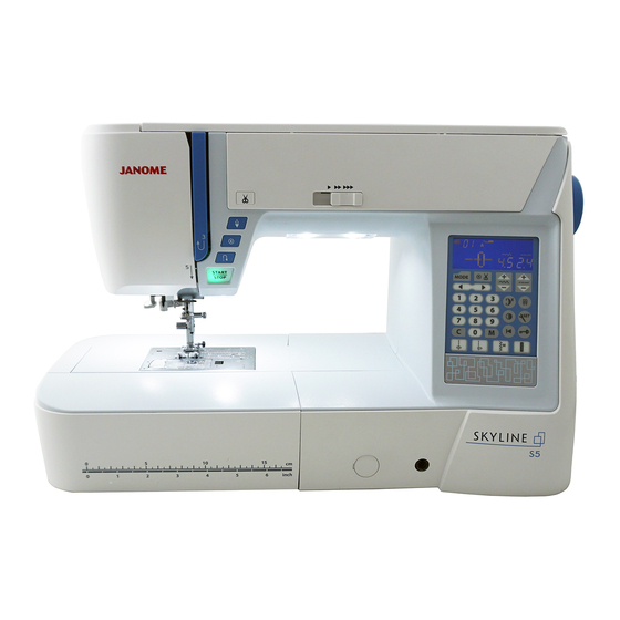
Summary of Contents for Janome Skyline S5
- Page 1 SERVICE MANUAL SKYLINE S5...
-
Page 2: Table Of Contents
INDEX Changing external parts Face cover ............................1 Belt cover ............................1 Top cover ............................2 Machine base ............................3 Base cover ............................3 Bed cover ............................3 Free arm cover ............................4 Front cover ............................5 Rear cover ............................6 Replacing electronic components Printed circuit board A .........................7 Printed circuit board F .........................8 Switching power supply unit ........................9 DC motor ............................10... -
Page 3: Changing External Parts
Changing external parts Face cover Face cover Setscrew A To remove: 1. Remove the setscrews A. Remove the face cover. To attach: 1. Follow the above procedure in reverse. Belt cover Setscrew A Belt cover To remove: 1. Remove the setscrews A and B. 2. -
Page 4: Top Cover
Changing external parts Top cover Setscrew A Top cover Fig. 1 To remove: 1. Raise the carrying handle and remove the setscrew A. 2. Open the top cover. Pull out the flange plate from the Face cover bobbin winder spindle (see fig. 2). Carrying 3. -
Page 5: Machine Base
Changing external parts Setscrew A Machine base Setscrew A Machine base To remove: 1. Remove the setscrews A. 2. Remove the machne base. To attach: 1. Follow the above procedure in reverse. Setscrew A Setscrew A Base cover Setscrew B Base cover Setscrew B To remove:... -
Page 6: Free Arm Cover
Changing external parts Needle plate release lever Free arm cover Needle plate To remove: 1. Remove the machine base and base cover (see page 3). Press the needle plate release lever to remove the needle plate. Free arm cover Hook B 2. -
Page 7: Front Cover
Changing external parts Front cover Setscrew A Setscrew A To remove: 1. Remove the top cover, belt cover, base cover, machine base and free arm cover (see pages 1-4). 2. Loosen the setscrews A (inside of the machine base). Setscrew B 3. -
Page 8: Rear Cover
Changing external parts Setscrew A Rear cover Rear cover Fig. 1 To remove: 1. Lower the presser foot. 2. Remove the belt cover, top cover and base cover (see pages 1, 2 and 3). 3. Loosen the setscrews A and B (see fig. 1). Remove the setscrews C (see fig. -
Page 9: Replacing Electronic Components
Replacing electronic components Printed circuit board A Setscrew NOTE: Do not disconnect the connectors by pulling on cord. To disconnect the connectors, grasp the connector, not the cord. To remove: 1. Remove the front cover. 2. Grasp the connector directly with your fingers and pull. Do not pull the lead wire, as this may damage the contact sleeve inside of the connector. -
Page 10: Printed Circuit Board F
Replacing electronic components Printed circuit board F o remove: 1. Remove the front cover (see page 5). 2. Disconnect the connector from the printed circuit board A (see page 7). 3. Remove the CS rings. 4. Remove the setscrews, and the printed circuit board F. CS rings To attach: 1. -
Page 11: Switching Power Supply Unit
Replacing electronic components Switching power supply unit Switching power supply unit To remove: 1. Remove the belt cover, the top cover and the front cover (see pages 1, 2 and 5). 2. Loosen the setscrew A. Remove the cord guide plate. (see fig. -
Page 12: Dc Motor
Replacing electronic components DC motor To remove: 1. Remove the belt cover, the top cover and the front cover (see pages 1, 2 and 5). 2. Disconnect the DC motor connector from the printed circuit board A (see page 7). 3. -
Page 13: Thread Tension Unit
Replacing electronic components Thread tension unit Fig. 1 To remove: Thread tension 1. Remove the top cover and the front cover (see pages release lever 1 and 5). Spring 2. Disconnect the solenoid 1 thread tension release connector from the printed circuit board A (see page 7). 3. -
Page 14: Mechanical Adjustment
Mechanical adjustment Feed dog height When the foot pressure dial is at “7” and the presser foot A is lowered, the highest position of the feed dog should be 0.80 to 0.90 mm from the surface of the needle plate. Adjustment 1: 1. -
Page 15: Needle Drop Position
Mechanical adjustment Needle drop position When the straight stitch is selected, the needle should be positioned in the center of the needle plate hole. When the needle drop position is set at "0.0" and "9.0", the clearance between the side of the needle and the needle hole should be 0.2 mm or more. -
Page 16: Presser Bar Height
Mechanical adjustment Presser bar height The clearance between the presser foot and the surface of the needle plate should be 6 mm when the presser foot is raised. The presser foot (zigzag foot A) should be pararell to the slot of the feed dog teeth when attached. To adjust: 1. -
Page 17: Hook Timing
Mechanical adjustment Clearance between needle and tip of the rotary hook The clearance between the needle and the point of hook should be -0.1 to +0.05 mm. Adjustment 1 1. Remove the bed cover (see page 3). 2. Turn the power switch ON, and select the zigzag stitch pattern 11. -
Page 18: Needle Bar Height
Mechanical adjustment Adjustment 2 1. Remove the top cover (see page 2). Needle plate hole 2. Remove the presser foot, the needle plate and the bobbin holder. (see page 4) * Cover the needle plate with the fabric to prevent damaging when removing the needle plate. - Page 19 Mechanical adjustment Hook timing The amount of ascending travel of the needle bar from its lowest position to the position (Needle drop position 0.0) where the tip of the rotary hook exactly meets the right side of the needle should be 3.70 to 4.00 mm (Needle drop position 0.0) To adjust: Needle #14...
- Page 20 Mechanical adjustment Needle bar height The distance between the upper edge of the needle eye and the hook race should be in the range of 1.6 to 2.0 mm when the tip of the hook meets right side of the needle in the needle drop position "0.0" as the needle ascends from its lowest position.
-
Page 21: Presser Bar Lifter Switch Position Adjustment
Mechanical adjustment Presser bar lifter switch position adjustment To check: 1. While pressing the needle up/down and lock stitch Presser foot symbol buttons, turn the power switch on. The LCD displays "----". 2. Press "5" key to enter the sensor test mode. 3. -
Page 22: Backlash Between Hook Drive Gear And Lower Shaft Gear
Mechanical adjustment Backlash between hook drive gear and lower shaft gear The rotary play of the hook should be 0.8 mm or less when the tip of rotary hook is within the width of feed dog. 1. Remove the base cover and bed cover (see page 3). 2. -
Page 23: Upper Shaft Shield Plate Position
Mechanical adjustment Upper shaft shield plate position When the machine is set for zigzag stitch, the needle should start to swing 7.2 to 8.2 mm above the surface of the needle plate. To check: 1. Attach the needle #14. 2. While pressing the needle up/down and lock stitch Needle #14 buttons, turn the power switch on. -
Page 24: Upper Thread Tension
Mechanical adjustment Upper thread tension The standard upper thread tension should be 75 to 90 grams when pulling the thread (while polyester thread size 50) at the speed of 110 mm/sec with the tension at "AUTO" (Be sure the presser foot is lowered). 1 Set the thread tension dial to "AUTO". -
Page 25: Needle Threader Plate
Mechanical adjustment Needle threader plate If the hook of the threader plate is damaged, change or adjust the part as follows: To remove: 1 Push down the needle threader knob and pull the Fig. 1 needle threader plate (A) down to remove it (see Fig. -
Page 26: Buttonhole Lever Adjustment
Mechanical adjustment Buttonhole lever adjustment To prepare: 1. While pressing the needle up/down and lock stitch buttons, turn the power switch on. The LCD display “----”. Press “5” key to enter the sesor test mode. 2. Attach the automatic buttonhole foot R. Place a piece of paper between the presser foot and the needle plate for easier adjustment. -
Page 27: Thread Cutter
Mechanical adjustment Thread cutter The distance between the end of thread cutter plate slit and the edge of moving cutter should be in the range of 0.4 to 1.2 To check: 1. Remove the bed cover and free arm cover (see page 3, 4). -
Page 28: Solenoid Position Adjustment
Mechanical adjustment Solenoid position adjustment When the tension disk is closed, the clearance between the plunger and the end of yoke should be 2.0 mm. TOP VIEW [To check] 1. While pressing the needle up/down and lock stitch buttons, turn the power switch on. The LCD display “----”. -
Page 29: Stretch Stitch Feed Balance
Mechanical adjustment Stretch stitch feed balance Adjust the stretch stitch balance dial C at the setting mark D. The measurement of five of test patterns should be in the range of 33 to 39 mm as shown. To adjust: 1. While pressing the needle up/down and lock stitch buttons, turn the power switch on. -
Page 30: Needle Plate Switch
Mechanical adjustment Needle plate switch Fig. 1 To check and adjustment: Needle plate sensor switch 1. Prepare the needle plate and the needle plate for straight stitch. 2. Insert the needle plate base plate under the fixed cutter spacer and the slide plate positioning plate. Press the ◎... - Page 31 Mechanical adjustment To check: 1. While pressing the needle up/down and lock stitch buttons, turn the power switch on. The LCD display “----”. Press “5” key to enter the sensor test mode. 2. Be sure that S symbol appears and blinks when the S symbol blinks needle plate is attached.
-
Page 32: Diagnosis Test
Diagnosis test NOTE: 1. Be sure to disconnect the macine from the power supply when replacing parts. 2. The language on the LCD is English only. Preparation 1. Shift the bobbin winder spindle to the right. 2. Turn the drop feed lever to the right (away from you) to raise the feed dog. 3. - Page 33 Diagnosis test STEP AND PROCEDURE CORRECT CONDITION DEFECTIVE CONDITION ITEMS T CHECk Turn on the power switch while Sewing lamp and LCD backlight lit. “1” button is not responding. LCD displays “----”. Sewing lamp does not lit. FUNCTION OF simultaneously pressing the LCD backlight does not lit.
- Page 34 Diagnosis test STEP AND PROCEDURE CORRECT CONDITION DEFECTIVE CONDITION ITEMS TO CHECk Buzzer does not sound. LCD displays “05” and presser foot Move the presser foot lifter up and Presser foot symbol does symbol. down. PRESSER not change. When the presser foot lifter is raised, FOOT If the result is correct condition, LIFTER...
- Page 35 Diagnosis test STEP AND PROCEDURE CORRECT CONDITION DEFECTIVE CONDITION ITEMS TO CHECk Attach the foot control to the LCD displays “08” and “FC”. The foot control symbol machine. does not appear. FOOT Depress the foot control as far as Buzzer does not sound. CONTROL it goes, then release it.
- Page 36 Diagnosis test STEP AND PROCEDURE CORRECT CONDITION DEFECTIVE CONDITION ITEMS TO CHECk LCD displays “12”, “SO” and “–off”. Lower the presser foot. The Thread tension disk THREAD Press the needle up/down button. does not open. Press the needle up/down button to TENSION If the result is correct condition, switch the solenoid on or off.
- Page 37 Diagnosis test STEP AND DEFECTIVE CONDITION PROCEDURE CORRECT CONDITION ITEMS TO CHECk LCD displays “15”. Buzzer does not sound. Attach the needle plate. NEEDLE Attach the needle plate for straight When the needle plate is attached to PLATE –REMEDY– stitch. the machine, LCD displays “PSZ”.
-
Page 38: Diagnosis Test
Diagnosis test To start the key position calibration: If the function keys seem out of alignment, calibrate the key position as follows. z While pressing the needle up/down and lock stitch buttons, turn the power switch on. The LCD screens display "----". x Press the auto-lock button button q to enter the key position calibration.
Need help?
Do you have a question about the Skyline S5 and is the answer not in the manual?
Questions and answers