Advertisement
Available languages
Available languages
Advertisement

Related Manuals for Opus Atlas 190


Summary of Contents for Opus Atlas 190
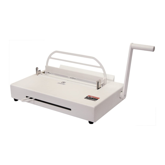
- Page 1 Atlas 190 • User’s guide Atlas 190 User’s guide...
-
Page 2: Table Of Contents
Metalbind is the strongest binding method. A special feature off the Atlas 190 is that it can also bind and de-bind covers from the C-Bind system. -
Page 3: Description
Atlas 190 • User’s guide DESCRIPTION 1 - bind and de-binding handle 2 - clamp lever 3 - binding slot 4 - de-binding hooks 5 - de-binding wedge (Metalbind) 6 - channel width selecting tool 7 - front bar of the COVERguide system 8 - back bar of the COVERguide system with ruler 9 - fixed side stop 10 - a djustable side stop 11 - extended back support HEALTH & SAFETY • Before operating the equipment read the Health & Safety precautions, manufacturers recommendations and the operation/user manual • The operation/user manual should be easily available at any time for the operator • The equipment must be kept away and out of reach of children • Equipment must be protected against dust and damp and should be positioned on a strong and sturdy flat surface • While binding, do not put fingers into the binding slot • Be careful when moving the equipment it is very heavy • Pay attention the de-binding wedge has sharp edges... -
Page 4: Preparation To Work
other than those indicated in the operating/user manual • It is necessary to check and supervise if the equipment is being used and operated correctly, before reporting any malfunctions or problems to the service department or dealer • Equipment must not be located outside or operated in temperatures under 8˚C / 46.4˚F and must be operated in accordance with the general Health & Safety rules failure to do so could cancel the guarantee • Repairs must be carried out by authorized staff, during the guarantee period, failure to do so could cancel the guarantee PREPARATION TO WORK After taking the device out of the packing box, start assembling the equipment, attach the extended back support (11) on to the lower back support, to the pre drilled holes with the Allen key and screws supplied, now fit the bind & de-binding handle (1) with the bolt and Allen key supplied, in the hole in the side and tightened firmly. Now place the two plastic bars called (COVER GUIDE SYSTEM) (7 & 8) in the binding slot (8) with the ruler at the back of the slot, and the second bar (7) with magnets at the front (see diagram on the opposite page) The cover guide system has been specially designed to help you insert the covers and documents into the channel easily and centre covers and documents when using smaller channels. It is very important that the cover guide system is fitted correctly in the binding slot (3) the sloped edges of the bars should be facing each other in the binding slot please check by looking at the diagram. (see diagram on the opposite page). The equipment is now ready for work. - Page 5 Atlas 190 • User’s guide Important! The thickness of the documentation 7 - front edge guide for binding jaw to be bound must be at least 1,8 mm 8 - back guide with ruler (with the cover). If the documentation is A - channel thinner, it is necessary to use the filling strips B - binding jaw called O.filling Sticky, available from OPUS...
-
Page 6: De-Binding With Metalbind
DE-BINDING WITH METALBIND 1. Lift the binding handle(1) up to the open position. 2. If fitted remove adjustable stop. 3. Ensure the clamp lever(2) is completely to the left,open. 4. Put the bound document flat on the equipment face down, back cover up. 5. Push the bound document, channel against the back support,firmly. 6. Open the bound document 5 to 6 pages from the back cover. De-binding 7. Fit the right end of the wedge (5) blade edge towards the channel, in the right hook (4) then place the left end of the wedge into the left hook (4). 8. Move the clamp lever (2) to the right till you feel some resistance, holding the lever. 9. Push down the binding handle (1) carefully, hol- ding the clamp lever (2) at the same time, move the handle (1) up and down at the same time move the clamp lever (2) to the right carefully until the pages are just loose enough to come out of the channel. 10. Lift the handle (1) up, release clamp lever (2) and re- move the document together with the wedge, then take the wedge out of the document carefully. 11. Make the planned changes to the document and re-bind. The cover may be re-used (a maximum of three times). -
Page 7: Technical Data
2. Documents to bind must have a minimum thickness of 1.8 mm, thinner must be bound using a filler strip called O.Filling Sticky from OPUS, these increase the thickness for binding. Before binding C-BIND covers remove the Metalbind binding bar (8) with ruler and insert the O.CB Insert for Atlas 190 binding bar, see (dig.1). 3. To de-bind C-BIND cover use O.CB de-binding wedge for Atlas 190 (Dig.2). Important! The AA cover de-binding jig tool included in the (O.CB Debinding Tool for Atlas 190) should be fitted on the spine edge of AA cover before debinding. 4. Follow the same binding and de-binding methods as in Metalbind, chapters 5 and 6. While binding or de-binding with C-Bind System, front or back of cover may face you. TECHNICAL DATA • Binds and de-binds up to 190 sheets* = 380 pages ** • Dimensions: H-180 x W-435 x D-320 mm • Net weight: 16.1 kg • Gross weight: 18.5 kg... - Page 9 Atlas 190 • Instrukcja obsługi Atlas 190 Instrukcja obs ugi...
- Page 10 4 Przygotowanie 8 Dane techniczne urządzenia do pracy SYSTEM METALBIND Urządzenie bindujące Atlas 190 jest przeznaczone do oprawiania dokumentacji (bindowania) przy użyciu okładek i kanałów wykonanych w systemie Metalbind. Bindowanie polega na zaciskaniu pliku kartek wraz z okładkami od zewnątrz przez metalowy kanał.
- Page 11 Atlas 190 • Instrukcja obsługi OPIS URZĄDZENIA 1 - ramię urządzenia 2 - uchwyt regulujący rozwarcie szczęk 3 - szczelina bindująca 4 - zaczep 5 - klin debindujący 6 - przyrząd doboru rozmiaru kanału/okładki 7 - magnetyczna wkładka prowadząca 8 - wkładka prowadząco - bindująca 9 - ogranicznik 10 - ruchomy ogranicznik 11 - pałąk ZASADY BEZPIECZEŃSTWA • przed rozpoczęciem pracy z urządzeniem należy zapoznać się z zasadami bezpieczeństwa, zaleceniami producenta i instrukcją obsługi • instrukcję tę należy zachować i korzystać z niej w przypadku jakichkolwiek wątpliwości dotyczących obsługi urządzenia • urządzenie należy chronić przed wilgocią i kurzem • urządzenie należy trzymać poza zasięgiem dzieci • urządzenie należy ustawić na stabilnej powierzchni o odpowiedniej wytrzymałości • w trakcie zaciskania nie wkładać rąk do szczeliny bindującej! • zachować ostrożność przy przenoszeniu urządzenia.
- Page 12 • należy kontrolować sprawność urządzenia. • w przypadku zauważenia jakichkolwiek nieprawidłowości w pracy, należy skontaktować się z serwisem • urządzenie jest przeznaczone wyłącznie do pracy w pomieszczeniach zamkniętych • urządzenie należy obsługiwać zawsze zgodnie z ogólnymi zasadami BHP • wszelkich napraw urządzenia może dokonywać jedynie osoba uprawniona. PRZYGOTOWANIE URZĄDZENIA DO PRACY Po wyjęciu urządzenia z opakowania, za pomocą załączonych kluczy imbusowych przykręć śrubami pałąk (11) do podpory debindującej oraz solidnie przykręć ramię urządzenia (1) do obudowy. Do urządzenia dołączone są dwie wkładki: • magnetyczna wkładka prowadząca (7) (znajduje się na szczelinie bindującej (3) • wkładka prowadząco-bindująca (8) (znajduje się w schowku z boku urządzenia razem z klinem debindującym) Połóż odpowiedniąwkładkę prowadząco-bindującą przy tylnej ścianie szczeliny bindującej (3) wraz zmagnetyczną wkładką prowadzącą (7). Prawidłowe ułożenie wkładek pokazuje przekrój poprzeczny na rysunku w rozdziale piątym (BINDOWANIE METALBIND).
- Page 13 1,8 mm (razem 8 - wkładka prowadząco–bindująca z okładką). Jeśli dokumentacja jest cień- 12 - szczęka bindująca sza, koniecznie użyj pasków wypełnia- (dociska prostą ściankę kanału) jących (np. O•Filling Sticky dostępnych 13 - kanał w ofercie OPUS) tak, aby zwiększyć grubość oprawianych dokumentów. 2. Upewnij się, że w szczelinie bindującej znajdują się odpowiednio ułożone wkładki, patrz rozdział czwarty (PRZYGOTOWANIE URZĄDZENIA DO PRACY). 3. Podnieś ramię urządzenia (1) maksymalnie do góry. 4. Przesuń uchwyt regulujący rozwarcie szczęk (2) maksymalnie w lewo. 5. Pomiędzy wkładkę (8) i szczękę (12) włóż kanał, a następnie dosuń go maksymalnie w prawo do ogranicznika (9). W przypadku kanałów mniejszych niż A4 należy zastosować...
- Page 14 DEBINDOWANIE METALBIND 1. Połóż dokument na maszynie tak, aby tylna okładka znajdowała się na górze. 2. Pałąk (11) odsuń maksymalnie do tyłu i zdemontuj ogranicznik ruchomy (10) (jeśli nie został już wcześniej usunięty). 3. Podnieś ramię urządzenia (1). 4. Otwórz dokument kilka milimetrów od tylnej okładki. 5. Wsuń prawy koniec klina debindującego (5) w prawy zaczep debindujący (4). Ścięta krawędź klina (5) musi być skierowana w stronę grzbietu dokumentu. 6. Przenieś lewy koniec klina debindującego (5) ponad lewymzaczepem (4), a na- stępnie zamocuj gowzaczepie. 7. Przesuń uchwyt (2) maksymalnie w prawo, aż DEBINDOWANIE napotka na opór. 8. Pchnij ramię bindownicy (1) w dół jednocześnie drugą ręką przytrzymując uchwyt regulujący rozwarcie szczęk (2). Po podniesieniu ramienia (1) za pomocą uchwytu (2) zredukuj powstały luz, a następnie kilkakrotnie powtórz czynność. 9. Ramię urządzenia (1) podnieś do góry. 10. Zdejmij klin z zaczepów debindujących (4) i delikatnie wyciągnij kanał z okładki. 11. Dokonaj zaplanowanych zmian w dokumentacji. Do ponownej oprawy możesz użyć tych samych okładek i kanału (maksymalnie trzy razy).
- Page 15 146-185 2. Oprawiana dokumentacja musi mieć grubość co najmniej 1,8 mm. Jeśli dokumen- tacja jest cieńsza, koniecznie użyj pasków wypełniających (np. O•Filling Sticky dostępnych w ofercie OPUS), tak aby zwiększyć grubość oprawianych dokumentów. 3. Do debindowania należy użyć klinu debindującego do okładek C-BIND (rys.2). Uwaga! W przypadku debindowania okładek w rozmiarze AA zastosuj specjalną nakładkę (znajdującą się w zestawie O.CB Debinding Tool for Atlas 190), którą należy włożyć na grzbiet oprawionej dokumentacji (rys.3). 4. Bindowanie i debindowanie okładek systemu C-BIND odbywa się analogicznie do syste- mu Metalbind. Podczas bindowania i debindowania okładka może znajdować się przo- dem lub tyłem do Ciebie, ułożenie klina nie ma znaczenia (jest symetryczny). DANE TECHNICZNE • maks ilość oprawianych kartek .
- Page 16 Oferta dotyczy maszyn w cenie zakupu do 1900 PLN netto. Firma OPUS ma przyjemność udzielić: 2 - letniej gwarancji na wszystkie urządzenia OPUS i niszczarki EBA 5 –letniej gwarancji na niszczarki IDEAL (do modelu 2503cc) Dożywotniej gwarancji na noże tnące w niszczarkach IDEAL i EBA...
- Page 17 Niespełnienie któregokolwiek z warunków daje prawo do odmowy wykonania naprawy gwarancyjnej. W razie utraty karty gwarancyjnej duplikaty nie będą wydawane. 5. Firma OPUS zobowiązuje się usunąć ewentualne uszkodzenia w terminie 14 dni roboczych od daty dostarczenia urządzenia do serwisu. Deklarujemy wykonanie naprawy urządzeń w cenie zakupu poniżej 1900 PLN netto w ciągu 72 godzin –program „Serwis 72 h”...
- Page 18 11. Okres gwarancji ulega przedłużeniu o czas trwania naprawy w serwisie OPUS (transport do i z serwisu nie jest wliczany w czas, o który przedłuża się obowiązywanie gwarancji).
- Page 19 Atlas 190 • User’s guide REJESTRACJA NAPRAW Data Data Opis Pieczęć L .p. przyjęcia wykonania naprawy i podpis serwisu Urządzenia prosimy dostarczać: do punktów sprzedaży, w których zakupiono maszynę lub bezpośrednio do serwisu: OPUS Sp. z o.o., 44 - 122 Gliwice, ul. Toruńska 8...
Need help?
Do you have a question about the Atlas 190 and is the answer not in the manual?
Questions and answers