
Subscribe to Our Youtube Channel
Related Manuals for National Instruments DAQ SC-205X Series


Summary of Contents for National Instruments DAQ SC-205X Series
- Page 1 SC-205 X Series User Manual SC-205 X Series User Manual November 1998 Edition Part Number 371176A-01...
- Page 2 Singapore 2265886, Spain 91 640 0085, Sweden 08 730 49 70, Switzerland 056 200 51 51, Taiwan 02 377 1200, United Kingdom 01635 523545 National Instruments Corporate Headquarters 6504 Bridge Point Parkway Austin, Texas 78730-5039 USA Tel: 512 794 0100 © Copyright 1989, 1998 National Instruments Corporation. All rights reserved.
-
Page 3: Important Information
90 days from date of shipment, as evidenced by receipts or other documentation. National Instruments will, at its option, repair or replace software media that do not execute programming instructions if National Instruments receives notice of such defects during the warranty period. -
Page 4: Table Of Contents
Contents About This Manual Organization of This Manual ..................xi Conventions Used in This Manual.................xii National Instruments Documentation ................xiii Related Documentation....................xiv Customer Communication .....................xiv Chapter 1 Introduction About the SC-205X Series .....................1-1 What You Need to Get Started ..................1-3 Unpacking ........................1-4 Software Programming Choices ..................1-4... - Page 5 SC-2056 Connection ..................... 8-2 Connectors ...................... 8-3 Mounting ........................8-16 Cabling .......................... 8-17 Chapter 9 SC-2057 SC-2057 Connection ..................... 9-2 Connectors ...................... 9-3 Mounting ........................9-12 Cabling .......................... 9-13 SCXI-1348 Cable Adapter Installation ............9-13 SC-205X Series User Manual © National Instruments Corporation...
- Page 6 Pin Assignments for SC-2051 I/O Connector J4........3-6 Figure 3-6. Pin Assignments for SC-2051 I/O Connector J5........3-7 Figure 4-1. SC-2052 Parts Locator Diagram ............4-2 Figure 4-2. SC-2052 Connections................4-4 Figure 4-3. Pin Assignments for SC-2052 I/O Connectors J1 and J2......4-5 © National Instruments Corporation SC-205X Series User Manual...
- Page 7 Pin Assignments for SC-2056 I/O Connector J9 ........8-14 Figure 8-12. Pin Assignments for SC-2056 I/O Connector J10 ........ 8-15 Figure 8-13. Pin Assignments for SC-2056 I/O Connector J11 ........ 8-15 SC-205X Series User Manual viii © National Instruments Corporation...
- Page 8 DAQ Hardware Used with the SC-205X Series Adapters ....1-2 Table 2-1. SC-2050 Connectors................2-4 Table 3-1. SC-2051 Connectors................3-4 Table 4-1. SC-2052 Connectors ................4-4 Table 5-1. SC-2053 Connectors................5-4 Table 6-1. SC-2054 Connectors ................6-4 Table 7-1. SC-2055 Connectors................7-3 Table 8-1. SC-2056 Connectors ................8-5 © National Instruments Corporation SC-205X Series User Manual...
- Page 9 Contents Table 9-1. SC-2057 Connectors ................9-9 Table 9-2. SCXI-1348 Pin Translations ..............9-15 SC-205X Series User Manual © National Instruments Corporation...
-
Page 10: About This Manual
• Chapter 10, Installation and Operation, describes the installation and operation of your SC-205X adapter, including configuration and cable connections. • Appendix A, Specifications, lists the specifications for the SC-205X Series adapters. © National Instruments Corporation SC-205X Series User Manual... -
Page 11: Conventions Used In This Manual
About This Manual • Appendix B, Customer Communication, contains forms you can use to request help from National Instruments or to comment on our products. • Glossary contains an alphabetical list and description of terms in this manual, including abbreviations, acronyms, metric prefixes, mnemonics, and symbols. -
Page 12: National Instruments Documentation
Consult these guides when you are making your connections. • SCXI Chassis User Manual—If you are using SCXI, read this manual for maintenance information on the chassis and for installation instructions. © National Instruments Corporation xiii SC-205X Series User Manual... -
Page 13: Related Documentation
AMUX-64T User Manual Customer Communication National Instruments wants to receive your comments on our products and manuals. We are interested in the applications you develop with our products, and we want to help if you have problems with them. To make it easy for you to contact us, this manual contains comment and configuration forms for you to complete. -
Page 14: Introduction
SC-205X Series adapters convert cables from the various DAQ devices to standard pin connections that match the SC-206X Series, 5B Series, SSR Series, and ER 8/16 signal conditioning accessories. Table 1-1 lists the National Instruments DAQ devices that you can use with the SC-205X Series adapters. © National Instruments Corporation... -
Page 15: Table 1-1. Daq Hardware Used With The Sc-205X Series Adapters
Table 1-1. DAQ Hardware Used with the SC-205 X Series Adapters DAQ Hardware Family SC-2050 SC-2051 SC-2052 SC-2053 SC-2054 SC-2055 SC-2056 SC-2057 E Series AT-MIO-16E-10 AT-MIO-16D AT-MIO-64E-3 AT-MIO-16DE-10 AT-MIO-16DE-10 PCI/PXI-6071E AT-MIO-16E-2 PCI/PXI-6031E, AT-MIO-16E-1 PCI-6033E AT-MIO-16E-3 VXI-MIO-64XE-10 AT-MIO-16XE-50 VXI-MIO-64E-1 AT-MIO-16XE-10 AT-AI-16XE-10 PCI-MIO-16E-4 PCI-MIO-16E-1 PCI-MIO-16XE-10... -
Page 16: What You Need To Get Started
Chapter 1 Introduction The SC-205X Series adapters link the National Instruments DAQ devices and the signal conditioning accessories. You can configure any usual combination of signal conditioners (for example, solid-state relays, optical isolators, electromechanical relays, or analog signal conditioning modules) quickly and easily by connecting the SC-205X Series adapter designed for that device. -
Page 17: Unpacking
DAQ device. Optional Equipment National Instruments offers a variety of products to use with your SC-205X Series adapter, including cables, connector blocks, rack-mount kits, and other accessories. - Page 18 The SC-2050 can be used with E Series devices such as the AT-MIO-16E-10, PCI-6031E, and DAQPad-MIO-16XE-50. See Table 1-1 for a complete list of DAQ devices that you can use with the SC-2050. © National Instruments Corporation SC-205X Series User Manual...
-
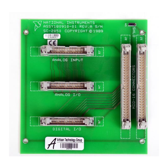
Page 19: Figure 2-1. Sc-2050 Parts Locator Diagram
4 To SC-207X, AMUX-64T, or CB-50 and Serial Number 5 To SC-206X Series or SSR Series 2 Shield Jumper 6 To 5B Series 3 To E Series device (MIO-16, etc.) Figure 2-1. SC-2050 Parts Locator Diagram SC-205X Series User Manual © National Instruments Corporation... -
Page 20: Sc-2050 Connection
Do not connect the SC-2050 to a board for which it is not designed. Such connection can damage the SC-2050 and any or all boards/accessories connected to the SC-2050 and host computer. National instruments is liable for any damages resulting from incorrect connections. -
Page 21: Figure 2-2. Sc-2050 Connections
8-channel boards. This connection takes the eight digital I/O lines from the E Series to a digital signal conditioning accessory with compatible pin connections, such as the SC-2060, SC-2061, SC-2062, or the 8-channel SSR Series backplane. SC-205X Series User Manual © National Instruments Corporation... -
Page 22: Figure 2-3. Pin Assignments For Sc-2050 I/O Connectors J1 And J2
PFI7/STARTSCAN 47 48 PFI8/GPCTR0_SOURCE PFI9/GPCTR0_GATE 49 50 GPCTR0_OUT FREQ_OUT Not available on all boards. Check your board's documentation for these signals. Figure 2-3. Pin Assignments for SC-2050 I/O Connectors J1 and J2 © National Instruments Corporation SC-205X Series User Manual... -
Page 23: Figure 2-4. Pin Assignments For Sc-2050 Analog Input Connector J3
15 16 ACH13 ACH5 17 18 AOGND ACH6 19 20 DAC0OUT DAC1OUT AOGND 21 22 ACH7 23 24 AOGND 25 26 AISENSE Figure 2-5. Pin Assignments for SC-2050 Analog I/O Connector J4 SC-205X Series User Manual © National Instruments Corporation... -
Page 24: Mounting
You need a 50-pin ribbon cable to connect the SC-2050. Connections to the SC-206X Series boards require a 26-pin ribbon cable. A 26-conductor ribbon cable is needed for the 8-channel SSR backplane. Additional cables are available from National Instruments for connection to other accessories. © National Instruments Corporation... - Page 25 6503 type devices. You can also use the SC-2051 with MIO devices having 24 additional digital channels, such as the AT-MIO-16DE-10. See Table 1-1 for a complete list of DAQ devices that you can use with the SC-2051. © National Instruments Corporation SC-205X Series User Manual...
-
Page 26: Figure 3-1. Sc-2051 Parts Locator Diagram
1 Product Name, Assembly Number, Revision Letter, and Serial Number 4 To CB-50 5 To SC-206 X Series or SSR Series 2 Shield Jumper 3 To DAQ device Figure 3-1. SC-2051 Parts Locator Diagram SC-205X Series User Manual © National Instruments Corporation... -
Page 27: Sc-2051 Connection
Do not connect the SC-2051 to a board for which it is not designed. Such connection can damage the SC-2051 and any or all boards/accessories connected to the SC-2051 and host computer. National instruments is liable for any damages resulting from incorrect connections. -
Page 28: Figure 3-2. Sc-2051 Connections
26-pin male connector; port B, port corresponding to the label below the or 1, digital I/O connection connector to the digital lines of the accessory. 26-pin male connector; port A, or 0, digital I/O connection SC-205X Series User Manual © National Instruments Corporation... -
Page 29: Figure 3-3. Pin Assignments For Sc-2051 I/O Connectors J1 And J2
31 32 33 34 35 36 37 38 39 40 41 42 43 44 45 46 47 48 49 50 +5 V Figure 3-3. Pin Assignments for SC-2051 I/O Connectors J1 and J2 © National Instruments Corporation SC-205X Series User Manual... -
Page 30: Figure 3-4. Pin Assignments For Sc-2051 I/O Connector J3
+5 V +5 V +5 V 11 12 13 14 15 16 17 18 19 20 21 22 23 24 25 26 +5 V Figure 3-5. Pin Assignments for SC-2051 I/O Connector J4 SC-205X Series User Manual © National Instruments Corporation... -
Page 31: Mounting
DAQ device. Connections to the SC-206X Series boards require a 26-pin ribbon cable. A 26-conductor ribbon cable is needed for the 8-channel SSR backplane. Additional cables are available from National Instruments for connection to other accessories. © National Instruments Corporation SC-205X Series User Manual... - Page 32 The SC-2052 converts 32 digital I/O signals to standard pin connections for signal conditioning accessories. You can use the SC-2052 with DIO-32 and 6533 type devices. See Table 1-1 for a complete list of DAQ devices that you can use with the SC-2052. © National Instruments Corporation SC-205X Series User Manual...
-
Page 33: Figure 4-1. Sc-2052 Parts Locator Diagram
1 Product Name, Assembly Number, Revision Letter, and Serial Number 4 To CB-50 2 Shield Jumper 5 To SC-206 X Series or SSR Series 3 To DIO-32 and 6533 devices Figure 4-1. SC-2052 Parts Locator Diagram SC-205X Series User Manual © National Instruments Corporation... -
Page 34: Sc-2052 Connection
Do not connect the SC-2052 to a board for which it is not designed. Such connection can damage the SC-2052 and any or all boards/accessories connected to the SC-2052 and the host computer. National instruments is liable for any damages resulting from incorrect connections. -
Page 35: Figure 4-2. Sc-2052 Connections
PCLK2 (OUT2) circuitry. Consult the user manual for your DAQ device for further details on the correct connection of these lines. Two-position screw terminal block; digital lines STOPTRIG1 (IN1) and PCLK1(OUT1) SC-205X Series User Manual © National Instruments Corporation... -
Page 36: Figure 4-3. Pin Assignments For Sc-2052 I/O Connectors J1 And J2
DIOA3 41 42 DIOA7 DIOA5 43 44 DIOB5 DIOB2 45 46 DIOB7 DIOB6 47 48 DIOB0 DIOB3 49 50 DIOB4 DIOB1 Figure 4-3. Pin Assignments for SC-2052 I/O Connectors J1 and J2 © National Instruments Corporation SC-205X Series User Manual... -
Page 37: Figure 4-4. Pin Assignments For Sc-2052 I/O Connector J3
DIOC6 11 12 DIOC5 13 14 DIOC4 15 16 DIOC3 17 18 DIOC2 19 20 DIOC1 21 22 DIOC0 23 24 25 26 Figure 4-5. Pin Assignments for SC-2052 I/O Connector J4 SC-205X Series User Manual © National Instruments Corporation... -
Page 38: Mounting
To ground the SC-2052 adapter to the chassis, set the jumper on the adapter as described in Chapter 10, Installation and Operation. © National Instruments Corporation SC-205X Series User Manual... -
Page 39: Cabling
DAQ device. Connections to the SC-206X Series boards require a 26-pin ribbon cable. A 26-conductor ribbon cable is needed for the 8-channel SSR backplane. Additional cables are available from National Instruments for connection to other accessories. SC-205X Series User Manual... - Page 40 You can use the SC-2053 with the Lab/1200 devices. See Table 1-1 for a complete list of DAQ devices that you can use with the SC-2053. © National Instruments Corporation SC-205X Series User Manual...
-
Page 41: Figure 5-1. Sc-2053 Parts Locator Diagram
4 To CB-50 or SC-2701 2 Shield Jumper 5 To SC-206 X Series or SSR Series 3 To Lab-NB, Lab-PC, or 1200 device 6 To 5B Series Figure 5-1. SC-2053 Parts Locator Diagram SC-205X Series User Manual © National Instruments Corporation... -
Page 42: Sc-2053 Connection
Do not connect the SC-2053 to a board for which it is not designed. Such connection can damage the SC-2053 and any or all boards/accessories connected to the SC-2053, and host computer. National instruments is liable for any damages resulting from incorrect connections. -
Page 43: Table 5-1. Sc-2053 Connectors
26-pin male connector; port B eight digital lines of the port corresponding to the digital I/O connection label below the connector to the digital lines of the accessory. 26-pin male connector; port C digital I/O connection SC-205X Series User Manual © National Instruments Corporation... -
Page 44: Figure 5-3. Pin Assignments For Sc-2053 I/0 Connectors J1 And J2
41 42 OUT0 GAT0 43 44 OUT1 GAT1 45 46 CLK1 OUT2 47 48 GAT2 CLK2 49 50 +5 V DGND Figure 5-3. Pin Assignments for SC-2053 I/0 Connectors J1 and J2 © National Instruments Corporation SC-205X Series User Manual... -
Page 45: Figure 5-4. Pin Assignments For Sc-2053 I/O Connector J3
+5 V +5 V +5 V 11 12 13 14 15 16 17 18 19 20 21 22 23 24 25 26 +5 V Figure 5-5. Pin Assignments for SC-2053 I/O Connector J4 SC-205X Series User Manual © National Instruments Corporation... -
Page 46: Mounting
To ground the SC-2053 adapter to the chassis, set the jumper on the adapter as described in Chapter 10, Installation and Operation. © National Instruments Corporation SC-205X Series User Manual... -
Page 47: Cabling
You need a 50-pin ribbon cable to connect the SC-2053. Connections to the SC-206X Series boards and 5B Series backplane require a 26-pin ribbon cable. A 26-conductor ribbon cable is needed for the 8-channel SSR backplane. Additional cables are available from National Instruments for connection to other accessories. SC-205X Series User Manual... - Page 48 You can use the SC-2054 with DIO-96 and 6508 devices. The SC-2054 also works with DIO-24 devices; however, the SC-2051 is a more appropriate solution. See Table 1-1 for a complete list of DAQ devices that you can use with the SC-2054. © National Instruments Corporation SC-205X Series User Manual...
-
Page 49: Sc-2054 Connection
Do not connect the SC-2054 to a board for which it is not designed. Such connection can damage the SC-2054 and any or all boards/accessories connected to the SC-2054 and host computer. National instruments is liable for any damages resulting from incorrect connections. -
Page 50: Connectors
96-channel DAQ device. Two SC-2054 adapters with a type NB5 or R1005050 cable have signal-conditioning compatible pin connections for all 96 signals on the DAQ device. © National Instruments Corporation SC-205X Series User Manual... -
Page 51: Table 6-1. Sc-2054 Connectors
J1. J7 is tied to PPI B (ports 3 to 5) or PPI D (ports 9 to 11), depending on which half of the type NB5 cable is attached to J1. SC-205X Series User Manual © National Instruments Corporation... - Page 52 NB5 cable is attached to J1. J10 is tied to port A of PPI B or D (port number 3 or 9), depending on which half of the type NB5 cable is attached to J1. © National Instruments Corporation SC-205X Series User Manual...
-
Page 53: Figure 6-3. Pin Assignments For Sc-2054 I/O Connectors J1 And J2
Type NB5 or R1005050 cable connector labeled pins 1-50 connector labeled pins 51-100 is attached to J1 or J2. is attached to J1 or J2. Figure 6-3. Pin Assignments for SC-2054 I/O Connectors J1 and J2 SC-205X Series User Manual © National Instruments Corporation... -
Page 54: Figure 6-4. Pin Assignments For Sc-2054 I/O Connectors J3 And J7
31 32 33 34 35 36 37 38 39 40 41 42 43 44 45 46 47 48 49 50 +5 V Figure 6-4. Pin Assignments for SC-2054 I/O Connectors J3 and J7 © National Instruments Corporation SC-205X Series User Manual... -
Page 55: Figure 6-5. Pin Assignments For Sc-2054 I/O Connectors J4 And J8
+5 V +5 V 11 12 13 14 15 16 17 18 19 20 21 22 23 24 25 26 +5 V Figure 6-6. Pin Assignments for SC-2054 I/O Connectors J5 and J9 SC-205X Series User Manual © National Instruments Corporation... -
Page 56: Mounting
96-channel DAQ device, depending on the device. Connections to the SC-206X Series boards require a 26-pin ribbon cable. A 26-conductor ribbon cable is needed for the 8-channel SSR backplane. Additional cables are available from National Instruments for connection to other accessories. © National Instruments Corporation... -
Page 57: Figure 7-1. Sc-2055 Parts Locator Diagram
Figure 7-1 shows the SC-2055 parts locator diagram. 1 Shield Jumper 4 Serial Number 2 PC-LPM-16/PnP or DAQCard-700 5 Assembly Number and Revision Letter 3 To CB-50 or SC-2702 6 Product Name Figure 7-1. SC-2055 Parts Locator Diagram © National Instruments Corporation SC-205X Series User Manual... -
Page 58: Sc-2055 Connection
Do not connect the SC-2055 to a board for which it is not designed. Such connection can damage the SC-2055 and any or all boards/accessories connected to the SC-2055 and host computer. National instruments is liable for any damages resulting from incorrect connections. -
Page 59: Table 7-1. Sc-2055 Connectors
Attach J6 to the SC-2061, SC-2062, or 8-channel SSR Series connection backplane. This connects the eight digital output lines from the DAQCard-700 or PC-LPM-16/PnP to a digital signal conditioning accessory with a compatible pin connections. © National Instruments Corporation SC-205X Series User Manual... -
Page 60: Figure 7-3. Pin Assignments For Sc-2055 I/O Connectors J1 And J2
* PC-LPM pin 20 is –12 V and pin 21 is +12 V. * DAQCard-700 pins 20 and 21 are not connected. Figure 7-3. Pin Assignments for SC-2055 I/O Connectors J1 and J2 SC-205X Series User Manual © National Instruments Corporation... -
Page 61: Figure 7-4. Pin Assignments For Sc-2055 Analog Input Connector J3
15 16 ACH13 ACH5 17 18 AIGND ACH6 19 20 ACH14 AIGND 21 22 DAC0 ACH7 23 24 DAC1 25 26 AIGND Figure 7-5. Pin Assignments for SC-2055 Analog I/O Connector J4 © National Instruments Corporation SC-205X Series User Manual... -
Page 62: Mounting
To ground the SC-2055 adapter to the chassis, set the jumper on the adapter as described in Chapter 10, Installation and Operation. SC-205X Series User Manual © National Instruments Corporation... -
Page 63: Cabling
You need a 50-pin ribbon cable to connect the SC-2055. Connections to the SC-206X Series boards and 5B backplanes require a 26-pin ribbon cable. A 26-conductor ribbon cable is needed for the 8-channel SSR backplane. Additional cables are available from National Instruments for connection to other accessories. © National Instruments Corporation... - Page 64 You can use the SC-2056 with E Series devices such as the AT-MIO-64E-3 and VXI-MIO-64E-1. See Table 1-1 for a complete list of DAQ devices that you can use with the SC-2056. © National Instruments Corporation SC-205X Series User Manual...
-
Page 65: Sc-2056 Connection
Do not connect the SC-2056 to a board for which it is not designed. Such connection can damage the SC-2056 and any or all boards/accessories connected to the SC-2056 and host computer. National instruments is liable for any damages resulting from incorrect connections. -
Page 66: Connectors
5B Series of analog signal conditioning modules. The digital port connector is compatible with the SC-206X Series digital signal conditioners as well as with the 8-channel SSR Series solid-state relay board. © National Instruments Corporation SC-205X Series User Manual... -
Page 67: Figure 8-2. Sc-2056 Connections
When using an SC-2040 or SC-2043, you must apply external power to the SC-204X Series boards. You can use up to four SC-2042 or SC-2043 boards, but do not use both adapters simultaneously while using the SC-2056. SC-205X Series User Manual © National Instruments Corporation... -
Page 68: Table 8-1. Sc-2056 Connectors
I/O 8-channel boards. This connection takes the connection eight digital I/O lines from the DAQ device to a digital signal conditioning accessory with compatible pin connections, as shown in Figure 8-2. © National Instruments Corporation SC-205X Series User Manual... - Page 69 DAQ device to channels 0–13 of the 5B Series backplane in sequential order. It also connects the voltage output signal DAC0OUT from the DAQ device to channel 14 of the 5B Series, and DAC1OUT to channel 15. SC-205X Series User Manual © National Instruments Corporation...
-
Page 70: Figure 8-3. Pin Assignments For Sc-2056 I/O Connector J1
ACH50 PFI2/CONV* ACH58 PFI3/GPCTR1SOURCE ACH51 PFI4/GPCTR1GATE ACH59 GPCTR1OUT ACH52 PFI5/UPDATE* ACH60 PFI6/WFTRIG ACH53 PFI7/STARTSCAN ACH61 PFI8/GPCTR0SOURCE ACH54 PFI9/GPCTR0GATE ACH62 GPCTR0OUT ACH55 FOUT ACH63 Figure 8-3. Pin Assignments for SC-2056 I/O Connector J1 © National Instruments Corporation SC-205X Series User Manual... -
Page 71: Figure 8-4. Pin Assignments For Sc-2056 I/O Connector J2
39 40 PFI1/TRIG2 PFI2/CONV* 41 42 PFI3/GPCTR1SOURCE PFI4/GPCTR1GATE 43 44 GPCTR1OUT PFI5/UPDATE* 45 46 PFI6/WFTRIG PFI7/STARTSCAN 47 48 PFI8/GPCTR0SOURCE PFI9/GPCTR0GATE 49 50 GPCTR0OUT FOUT Figure 8-4. Pin Assignments for SC-2056 I/O Connector J2 SC-205X Series User Manual © National Instruments Corporation... -
Page 72: Figure 8-5. Pin Assignments For Sc-2056 I/O Connector J3
39 40 ACH50 ACH58 41 42 ACH51 ACH59 43 44 ACH52 ACH60 45 46 ACH53 ACH61 47 48 ACH54 ACH62 49 50 ACH55 ACH63 Figure 8-5. Pin Assignments for SC-2056 I/O Connector J3 © National Instruments Corporation SC-205X Series User Manual... -
Page 73: Figure 8-6. Pin Assignments For Sc-2056 I/O Connector J4
PFI1/TRIG2 PFI2/CONV* 41 42 PFI3/GPCTR1SOURCE PFI4/GPCTR1GATE 43 44 GPCTR1OUT PFI5/UPDATE* 45 46 PFI6/WFTRIG PFI7/STARTSCAN 47 48 PFI8/GPCTR0SOURCE PFI9/GPCTR0GATE 49 50 GPCTR0OUT FOUT Figure 8-6. Pin Assignments for SC-2056 I/O Connector J4 SC-205X Series User Manual 8-10 © National Instruments Corporation... -
Page 74: Figure 8-7. Pin Assignments For Sc-2056 I/O Connector J5
PFI1/TRIG2 PFI2/CONV* 41 42 PFI3/GPCTR1SOURCE PFI4/GPCTR1GATE 43 44 GPCTR1OUT PFI5/UPDATE* 45 46 PFI6/WFTRIG PFI7/STARTSCAN 47 48 PFI8/GPCTR0SOURCE PFI9/GPCTR0GATE 49 50 GPCTR0OUT FOUT Figure 8-7. Pin Assignments for SC-2056 I/O Connector J5 © National Instruments Corporation 8-11 SC-205X Series User Manual... -
Page 75: Figure 8-8. Pin Assignments For Sc-2056 I/O Connector J6
PFI1/TRIG2 PFI2/CONV* 41 42 PFI3/GPCTR1SOURCE PFI4/GPCTR1GATE 43 44 GPCTR1OUT PFI5/UPDATE* 45 46 PFI6/WFTRIG PFI7/STARTSCAN 47 48 PFI8/GPCTR0SOURCE PFI9/GPCTR0GATE 49 50 GPCTR0OUT FOUT Figure 8-8. Pin Assignments for SC-2056 I/O Connector J6 SC-205X Series User Manual 8-12 © National Instruments Corporation... -
Page 76: Figure 8-9. Pin Assignments For Sc-2056 I/O Connector J7
PFI1/TRIG2 PFI2/CONV* 41 42 PFI3/GPCTR1SOURCE PFI4/GPCTR1GATE 43 44 GPCTR1OUT PFI5/UPDATE* 45 46 PFI6/WFTRIG PFI7/STARTSCAN 47 48 PFI8/GPCTR0SOURCE PFI9/GPCTR0GATE 49 50 GPCTR0OUT FOUT Figure 8-9. Pin Assignments for SC-2056 I/O Connector J7 © National Instruments Corporation 8-13 SC-205X Series User Manual... -
Page 77: Figure 8-10. Pin Assignments For Sc-2056 I/O Connector J8
15 16 ACH61 ACH53 17 18 AIGND ACH54 19 20 ACH62 ACH63 AIGND 21 22 ACH55 23 24 AIGND 25 26 AISENSE2 Figure 8-11. Pin Assignments for SC-2056 I/O Connector J9 SC-205X Series User Manual 8-14 © National Instruments Corporation... -
Page 78: Figure 8-12. Pin Assignments For Sc-2056 I/O Connector J10
15 16 ACH29 ACH21 17 18 AIGND ACH22 19 20 ACH30 AIGND 21 22 ACH31 ACH23 23 24 AIGND 25 26 AIGND Figure 8-13. Pin Assignments for SC-2056 I/O Connector J11 © National Instruments Corporation 8-15 SC-205X Series User Manual... -
Page 79: Mounting
To ground the SC-2056 adapter to the chassis, set the jumper on the adapter as described in Chapter 10, Installation and Operation. SC-205X Series User Manual 8-16 © National Instruments Corporation... -
Page 80: Cabling
SH96-100 shielded cable to connect to the SC-2056. Connections to the SC-206X Series boards and 5B backplane require a 26-pin ribbon cable. A 26-conductor ribbon cable is needed for the 8-channel SSR backplane. Additional cables are available from National Instruments for connection to other accessories. © National Instruments Corporation... - Page 81 The SC-2057 converts VXI-DIO-128 I/O connector signals to AT-DIO-32F connectors, which can connect to standard signal conditioning accessories. You can use the SC-2057 with the National Instruments VXI-DIO-128 board. See Table 1-1 for a complete list of DAQ devices that you can use with the SC-2057.
-
Page 82: Sc-2057 Connection
The VXI-DIO-128 has a 96-pin connector labeled OUTPUT. The digital lines from this connector are digital outputs. The VXI-DIO-128 has a 96-pin connector labeled INPUT. The digital lines from this connector are digital inputs. SC-205X Series User Manual © National Instruments Corporation... -
Page 83: Connectors
Do not connect the SC-2057 to a board for which it is not designed. Such Warning connection can damage the SC-2057 and any or all boards/accessories connected to the SC-2057 and VXI-DIO-128. National instruments is liable for any damages resulting from incorrect connections. -
Page 84: Figure 9-2. Output Connections With The Scxi-1163/R
Warning directly to ground or to any other voltage source on the VXI-DIO-128, SC-2057, or any other device. Doing so can damage the VXI-DIO-128, SC-2057, and your VXIbus system. National Instruments is liable for damage resulting from such a connection. -
Page 85: Output Connections With The 32 Channel Ssr Backplane
* An external power supply is needed if more than 1 A of current is required to power the SSR backplanes. The current requirements for the SSR modules are as follows: SSR-OAC-5: 18 mA, SSR-OAC-5A: 19 mA, and SSR-ODC-5: 16 mA. © National Instruments Corporation SC-205X Series User Manual... -
Page 86: Output Connections With The Sc-2061/2, Er-8, Or 8-Channel Ssr Backplane
The board current requirements are as follows: SC-2061: 130 mA, SC-2062: 630 mA, and ER-8: 500 mA. The current requirements for the SSR modules are as follows: SSR-OAC-5: 18 mA, SSR-OAC-5A: 19 mA, and SSR-ODC-5: 16 mA. SC-205X Series User Manual © National Instruments Corporation... -
Page 87: Figure 9-6. Input Connections With The Scxi-1162/Hv
* If more than 1 A of current is required to power the SSR backplanes, an external power supply is needed, see Figure 9-7. The current requirements for the SSR modules are as follows: SSR-IAC-5: 16 mA, SSR-IAC-5A: 16 mA, and SSR-IDC-5: 16 mA. © National Instruments Corporation SC-205X Series User Manual... -
Page 88: Figure 9-8. Input Connections With Sc-2060 And 8-Channel Ssr Backplane
The board current requirement is 210 mA for the SC-2060. The current requirements for the SSR modules are as follows: SSR-IAC-5: 18 mA, SSR-IAC-5A: 19 mA, and SSR-IDC-5: 16 mA. Set the power switch on the SC-2060 boards to external. SC-205X Series User Manual © National Instruments Corporation... -
Page 89: Table 9-1. Sc-2057 Connectors
Attach J5 to accessories if possible or connection when +5 V is needed. 2-position terminal block; +5 V at 1 A Attach J6 to accessories if possible or connection when +5 V is needed. © National Instruments Corporation SC-205X Series User Manual... -
Page 90: Figure 9-9. Pin Assignments For Sc-2057 I/O Connector P1 And P2
Port 6/14_Line4 Port 7/15_Line1 Port 7/15_Line0 Port 6/14_Line7 Port 7/15_Line4 Port 7/15_Line3 Port 7/15_Line2 Port 7/15_Line7 Port 7/15_Line6 Port 7/15_Line5 Figure 9-9. Pin Assignments for SC-2057 I/O Connector P1 and P2 SC-205X Series User Manual 9-10 © National Instruments Corporation... -
Page 91: Figure 9-10. Pin Assignments For Sc-2057 I/O Connector J1
Port 0/9_Line5 Port 1/9_Line2 45 46 Port 1/9_Line7 Port 1/9_Line6 47 48 Port 1/9_Line0 Port 1/9_Line3 49 50 Port 1/9_Line4 Port 1/9_Line1 Figure 9-10. Pin Assignments for SC-2057 I/O Connector J1 © National Instruments Corporation 9-11 SC-205X Series User Manual... -
Page 92: Mounting
SC-2057, see the Rack Mounting section in Chapter 10, Installation Operation. To ground the SC-2057 adapter to the chassis, set the jumper on the adapter as described in Chapter 10, Installation and Operation. SC-205X Series User Manual 9-12 © National Instruments Corporation... -
Page 93: Cabling
Figure 9-12 shows how to connect the SCXI-1348 to the SC-2057 and SCXI module. J2 J1 1 SCXI-1348 cable adapter 3 SC-2057 2 NB1 ribbon cable 4 SCXI chassis Figure 9-12. Connecting the SCXI-1348 to the SC-2057 and SCXI Module © National Instruments Corporation 9-13 SC-205X Series User Manual... - Page 94 Connect one end of the 50-pin ribbon cable to the adapter board rear connector. Connect the loose end of the ribbon cable to either of the 50-pin connectors, J1 or J2, on the SC-2057. SC-205X Series User Manual 9-14 © National Instruments Corporation...
-
Page 95: Table 9-2. Scxi-1348 Pin Translations
Port 0/4_Line5 Port 1/5_Line5 Port 1/5_Line2 Port 1/5_Line7 Port 1/5_Line6 Port 1/5_Line0 Port 1/5_Line3 Port 1/5_Line4 Port 1/5_Line1 *All GND pins are connected to each other on the SCXI-1348 adapter board. © National Instruments Corporation 9-15 SC-205X Series User Manual... -
Page 96: Installation And Operation
19-in. rack. Since the SH96-96 cable will need to be routed from the top or bottom of the rack, the metal wraparound cover cannot be used with the SC-2057. © National Instruments Corporation 10-1 SC-205X Series User Manual... -
Page 97: Figure 10-1. Sc-2056 Adapter Mounted In A 19-In. Rack
Figure 10-2. Top Washer and Screw Metal Standoff Circuit Board Mounting Rack Mount Washer Screw Figure 10-2. Attaching a Mountable Board to a Chassis SC-205X Series User Manual 10-2 © National Instruments Corporation... -
Page 98: Shield Selection
W1 set to the position away from SHLD, so shielding is disabled. Jumper W1 settings are shown in Figure 10-4. SHLD SHLD Shield Disconnected Shield Connected Figure 10-4. Ground Settings for Jumper W1 © National Instruments Corporation 10-3 SC-205X Series User Manual... -
Page 99: Sc-2056
Figure 10-6 shows the ground settings for SC-2056 jumper W1. SH100100 Cable Shield SH100100 Cable Shield Chassis Ground Chassis Ground MIO Digital Ground MIO Digital Ground Factory Default Figure 10-6. Ground Settings for SC-2056 Jumper W1 SC-205X Series User Manual 10-4 © National Instruments Corporation... -
Page 100: Sc-2057
The SC-2057 is shipped from the factory with the jumper W1 set to the position between the CABLE SHIELD and CHASSISGND. Figure 10-8 shows the ground settings for SC-2057 jumper W1. © National Instruments Corporation 10-5 SC-205X Series User Manual... -
Page 101: Signal Conditioning Accessory Installation
SC-205X adapter. For more details, consult the SC-206X Series User Manual. Additional hardware for double-height mounting within a single rack for four or more SC Series boards is available from National Instruments. Rack-Mount Chassis Cover Attachment The optional 19-in. rack-mount accessory includes a flat, acrylic plastic cover that you can install with the four screws supplied in the kit. - Page 102 SC-206X Series User Manual, the 5B Series User Manual, the SC-207X Series User Manual, the AMUX-64T User Manual, or the user manuals for your SSR Series backplane and CB-50 terminal block. © National Instruments Corporation 10-7 SC-205X Series User Manual...
-
Page 103: Appendix A Specifications
Terminals Female Male SC-2050 SC-2051 SC-2052 SC-2053 SC-2054 SC-2055 SC-2056 SC-2057 Environment Operating temperature......0° to 70° C Storage temperature ....... –55° to 150° C Relative humidity ........5% to 90% noncondensing © National Instruments Corporation SC-205X Series User Manual... - Page 104 Electronic Services Bulletin Board Support National Instruments has BBS and FTP sites dedicated for 24-hour support with a collection of files and documents to answer most common customer questions. From these sites, you can also download the latest instrument drivers, updates, and example programs. For recorded instructions on how to use the bulletin board and FTP services and for BBS automated information, call 512 795 6990.
- Page 105 Telephone and Fax Support National Instruments has branch offices all over the world. Use the list below to find the technical support number for your country. If there is no National Instruments office in your country, contact the source from which you purchased your software to obtain support.
-
Page 106: Technical Support Form
National Instruments for technical support helps our applications engineers answer your questions more efficiently. If you are using any National Instruments hardware or software products related to this problem, include the configuration forms from their user manuals. Include additional pages if necessary. - Page 107 Complete a new copy of this form each time you revise your software or hardware configuration, and use this form as a reference for your current configuration. Completing this form accurately before contacting National Instruments for technical support helps our applications engineers answer your questions more efficiently.
- Page 108 Documentation Comment Form National Instruments encourages you to comment on the documentation supplied with our products. This information helps us provide quality products to meet your needs. Title: SC-205X Series User Manual Edition Date: November 1998 Part Number: 371176A-01 Please comment on the completeness, clarity, and organization of the manual.
- Page 109 µ- micro- – 6 –3 milli- kilo- mega- giga- tera- Numbers/Symbols ° degrees Ω ohms percent ± plus or minus +5 V +5 V signal amperes alternating current ACH# analog channel analog-to-digital © National Instruments Corporation SC-205X Series User Manual...
- Page 110 D/A converter DAC#OUT voltage output signal DAC1UNI/B1* DAC1 unipolar/bipolar bit data acquisition direct current DIGGND/DGND digital ground signal digital input signal digital I/O dynamic link library direct memory access SC-205X Series User Manual © National Instruments Corporation...
- Page 111 EXTSTROBE external strobe signal EXTUPDATE external update signal FOUT frequency output signal GATE# gate signal ground signal hexadecimal hertz Integrated Development Environment inch input signal integral nonlinearity input/output Industry Standard Architecture © National Instruments Corporation SC-205X Series User Manual...
- Page 112 Glossary light-emitting diode meter megabytes of memory not connected (signal) output signal port A port B port C Programmable Peripheral Interface parts per million root mean square samples seconds SC-205X Series User Manual © National Instruments Corporation...
- Page 113 TRIG# trigger signal TPCX Turbo Pascal Compiler UPDATE update signal volts positive supply voltage from the PCMCIA bus (usually +5V) volts, direct current WFTRIG waveform trigger signal WRTPRT write protect bit © National Instruments Corporation SC-205X Series User Manual...
- Page 114 SC-2056 (figure), 10-4 adapters (table), 1-2 SC-2057 (figure), 10-6 documentation shield selection (figure), 10-3 conventions used in manual, xii-xiii shield selection, 10-3 National Instruments documentation, xiii organization of manual, xi-xii related documentation, xiv © National Instruments Corporation SC-205X Series User Manual...
- Page 115 1-4 connectors, 4-3 to 4-7 overview, 1-1 to 1-3 illustration, 4-4 requirements for getting started, 1-3 to 1-4 J1 and J2 connector pin assignments software programming choices, 1-4 (figure), 4-5 unpacking, 1-4 SC-205X Series User Manual © National Instruments Corporation...
- Page 116 J1 pin assignments (figure), 8-7 J1 and J2 connector pin assignments J1 through J13 connections (table), (figure), 6-6 8-5 to 8-6 J1 through J10 connectors (table), 6-4 J2 connector pin assignments to 6-5 (figure), 8-8 © National Instruments Corporation SC-205X Series User Manual...
- Page 117 10-6 connections, 9-2 to 9-3 specifications connectors, 9-3 to 9-12 environment, A-1 J1 connector pin assignments physical, A-1 (figure), 9-11 J1 through J6 connectors (table), 9-9 J2 connector pin assignments (figure), 9-12 SC-205X Series User Manual © National Instruments Corporation...
- Page 118 Index technical support, B-1 to B-2 telephone and fax support numbers, B-2 © National Instruments Corporation SC-205X Series User Manual...
Need help?
Do you have a question about the DAQ SC-205X Series and is the answer not in the manual?
Questions and answers