Table of Contents
Advertisement
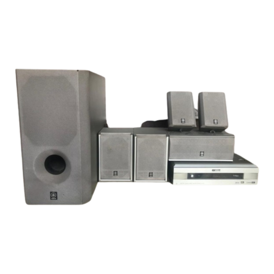
VS-10/NX-SW10
NX-SW10 is composed of SW-VS10, NX-VS10C and NX-VS10E.
Rear Speaker
NX-VS10E
Front Speaker
NX-VS10M
This manual has been provided for the use of authorized YAMAHA Retailers and their service personnel.
It has been assumed that basic service procedures inherent to the industry, and more specifically YAMAHA Products, are already known and understood by the users,
and have therefore not been restated.
WARNING:
Failure to follow appropriate service and safety procedures when servicing this product may result in personal injury, destruction of expensive
components, and failure of the product to perform as specified. For these reasons, we advise all YAMAHA product owners that any service required
should be performed by an authorized YAMAHA Retailer or the appointed service representative.
IMPORTANT:
The presentation or sale of this manual to any individual or firm does not constitute authorization, certification or recognition of any applicable
technical capabilities, or establish a principle-agent relationship of any form.
The data provided is believed to be accurate and applicable to the unit(s) indicated on the cover. The research, engineering, and service departments of YAMAHA are
continually striving to improve YAMAHA products. Modifications are, therefore, inevitable and specifications are subject to change without notice or obligation to
retrofit. Should any discrepancy appear to exist, please contact the distributor's Service Division.
WARNING:
Static discharges can destroy expensive components. Discharge any static electricity your body may have accumulated by grounding yourself to the
ground buss in the unit (heavy gauge black wires connect to this buss).
IMPORTANT:
Turn the unit OFF during disassembly and part replacement. Recheck all work before you apply power to the unit.
CONTENTS
TO SERVICE PERSONNEL .......................................... 1
REMOTE CONTROL TRANSMITTER PANELS ........... 1
FRONT/REAR PANELS ............................................ 2~4
SPECIFICATIONS .......................................................... 5
DIMENSIONS ................................................................. 6
INTERNAL VIEW ........................................................... 7
VS-10 DISASSEMBLY PROCEDURES ........................ 7
P. C. B. OPERATION CHECK ....................................... 8
1 0 0 7 3 3
HOME THEATER SYSTEM
Center Speaker
NX-VS10C
VS-10 is composed of VS-10 and NX-VS10M.
Home Theater System
VS-10
IMPORTANT NOTICE
SERVICE MANUAL
Rear Speaker
NX-VS10E
Front Speaker
NX-VS10M
SW-VS10 DISASSEMBLY PROCEDURES .................. 9
TEST PROGRAM MODE (VS-10) ......................... 10~11
DSP DIAG MODE (Self-diagnosis) ...................... 12~18
IC DATA ................................................................. 19~25
BLOCK DIAGRAM ................................................. 26~29
PRINTED CIRCUIT BOARD .................................. 30~41
SCHEMATIC DIAGRAM ........................................ 42~46
PARTS LIST ........................................................... 47~63
DISPLAY DATA ........................................................... 64
REMOTE CONTROL TRANSMITTER .................. 65~66
VS-10/NX-SW10
Subwoofer
SW-VS10
P.O.Box 1, Hamamatsu, Japan
Advertisement
Table of Contents

Related Manuals for Yamaha VS-10


Summary of Contents for Yamaha VS-10
-
Page 1: Table Of Contents
The data provided is believed to be accurate and applicable to the unit(s) indicated on the cover. The research, engineering, and service departments of YAMAHA are continually striving to improve YAMAHA products. Modifications are, therefore, inevitable and specifications are subject to change without notice or obligation to retrofit. -
Page 2: To Service Personnel
VS-10/NX-SW10 TO SERVICE PERSONNEL 1. Critical Components Information AC LEAKAGE Components having special characteristics are marked s WALL EQUIPMENT TESTER OR and must be replaced with parts having specifications equal OUTLET UNDER TEST EQUIVALENT to those originally installed. 2. Leakage Current Measurement (For 120V Models Only) -
Page 3: Front/Rear Panels
VS-10/NX-SW10 FRONT/REAR PANELS VS-10 U, C models A model... - Page 4 VS-10/NX-SW10 B, G model NX-VS10M SW-VS10 (Subwoofer) U, C models...
- Page 5 VS-10/NX-SW10 A model B, G model NX-VS10C (Center Speaker) NX-VS10E (Rear Speaker)
-
Page 6: Specifications
VS-10/NX-SW10 SPECIFICATIONS VS-10 (Center Unit) SW-VS10 (Subwoofer) Minimum RMS Output Power per Channel Audio Section SW-VS10: 1kHz, 10% THD, 5Ω Minimum RMS Output Power per Channel NX-VS10C: 1kHz, 10% THD, 6Ω 1kHz, 10% THD, 6Ω 25W + 25W NX-VS10E: 1kHz, 10% THD, 6Ω... -
Page 7: Dimensions
VS-10/NX-SW10 DIMENSIONS VS-10 NX-VS10M 125 (4-15/16") 145 (5-11/16") Unit : mm (inch) 302 (11-7/8") Unit : mm (inch) SW-VS10 (Subwoofer) 200 (7-7/8") 400 (15-3/4") Unit : mm (inch) NX-VS10C (Center Speaker) NX-VS10E (Rear Speaker) 112 (4–3/8") 100 (3–15/16") 240 (9-7/16") 145 (5-11/16") -
Page 8: Internal View
5 DIGITAL P.C.B. (3) 6 MAIN P.C.B. (5) 7 DIGITAL P.C.B. (2) 8 DIGITAL P.C.B. (1) VS-10 DISASSEMBLY PROCEDURES (Remove parts in the order as numbered below.) 1. Removal of Side Cover a. Remove 4 screws (1). (Fig. 1) b. Remove the Side Cover. -
Page 9: Operation Check
VS-10/NX-SW10 P.C.B. OPERATION CHECK Preparation before operation check a. Remove 3 screws (6). (Fig. 4) b. Remove the DSP Top Cover. c. Disconnect the flexible flat cable (CB1) from DIGITAL P.C.B. (1). (Fig. 4) d. Remove 4 screws (7) and then remove DIGITAL P.C.B. -
Page 10: Sw-Vs10 Disassembly Procedures
VS-10/NX-SW10 SW-VS10 DISASSEMBLY PROCEDURES (Remove parts in the order as numbered below.) Grill Assembly 1. Removal of Grille Assembly. a. Insert the tip of flat tip (-) screwdriver to the slot on the bottom. Push up the Grille Assembly by applying force to the screwdriver. -
Page 11: Test Program Mode
VS-10/NX-SW10 TEST PROGRAM MODE (VS-10) 1. Procedure for starting Test Program With the power turned off, press the POWER key while pressing the VOLUME key and the DSP key simultaneously. This initiates the Test Program function. When the Test Program is initiated, “01 DEST-Ex” appears on the FL display. - Page 12 Check sum calculation display / re-calculation 08 PrCan-OFF All protection cancellation function ON/OFF * 09 Pr!C–P–S– Protection operation history display / clear C: VS-10 amplifier voltage (DC) P: Power supply circuit voltage S: SW-VS10 (Subwoofer) side –: Normal x: Abnormal...
-
Page 13: Dsp Diag Mode (Self-Diagnosis)
VS-10/NX-SW10 DSP DIAG MODE (Self-diagnosis) Use the remote controller supplied as an accessory to select the menu. 1. Procedure for starting DSP DIAG Referring to TEST PROGRAM MODE in the previous section, select/execute “05 DSP Diag”. When “05 DSP Diag” is executed, the current input name appears on the display followed by “Sel.1to9 Key”. - Page 14 VS-10/NX-SW10 Details of DIAG menu 1. Analog Thr. The input is fixed to use the analog (A/D) and has 2 sub-menu items. MAIN BYPSS The main L/R signal is output through the analog bypass without passing the DSP section. The main L/R signal passing through the DSP is output through C/LFE and RL/RR.
- Page 15 VS-10/NX-SW10 2. DSP Through In the DIGITAL input mode, AC3/PCM AUDIO signal is automatically identified. There are 3 sub-menu items. YSS918-SRAM The main L/R signal is sent through AC3D2av into DSP. After passing through SRAM, the main L/R signal is output through L+R and C/LFE and RL/RR signals through (L+R)/2.
- Page 16 VS-10/NX-SW10 DSP FULL BIT The main L/R is input through AC3D2av to DSP and then output through all channels. The same applies as “YSS918” except that the digital data is output in full bit at D/A. VIDEO2 IN – 20dBV, Both ch...
- Page 17 VS-10/NX-SW10 4. Pro Logic The sub-menu items include selection of Pro-logic (The auto input balance is off.) and EFFECT OFF. CENTER LARGE When the analog, PCM audio or AC-3 2/0 mode is used, L, R, C, S signals are pro- logic decoded and output.
- Page 18 VS-10/NX-SW10 5. Speakers Set (for reference only) This menu is for checking during the production process and not for servicing. The input L/R signal is output through the specified channels according to the sub-menu. There are 7 sub-menu items. The signal output from the DSP section is normally in the EFFECT OFF state in the menus from 1 to 3.
- Page 19 VS-10/NX-SW10 6. Effect Off All effect functions are turned off. 7. Manual Test The test noise is output by the noise generator with a built-in DSP through the channels specified by the sub-menu. Noise is output through all channels. MAIN L Noise is output through the MAIN L channel.
-
Page 20: Ic Data
VS-10/NX-SW10 IC DATA µ IC600 : M30218FCFP (16 bit -COM) P67/FLD7 P24/FLD36 P66/FLD6 P25/FLD37 P65/FLD5 P26/FLD38 P64/FLD4 P27/FLD39 P63/FLD3 P30/FLD40 P62/FLD2 P31/FLD41 P61/FLD1 P32/FLD42 P60/FLD0 P33/FLD43 P34/FLD44 P107/AN7 P35/FLD45 P106/AN6 P36/FLD46 P105/AN5 P37/FLD47 P104/AN4 P40/FLD48 P103/AN3 P41/FLD49 P102/AN2 P42/FLD50 P101/AN1... - Page 21 VS-10/NX-SW10 µ IC600 : M30218FCFP (16 bit -COM) PORT Name IN/OUT Function CMOS (DSP) /IC AC3D OUT (/ICAC) CLK1 S-CLK (DSP) AC3D CLK OUT(CLKAC) (Serial I/O-1) RxD1 S-IN (DSP) AC3D DATA IN(RXAC) (Serial I/O-1) TxD1 S-OUT (DSP) AC3D DATA OUT(TXAC)
- Page 22 VS-10/NX-SW10 µ IC600 : M30218FCFP (16 bit -COM) PORT Name IN/OUT Function FLD10 SEGMENT 25 (P25) (VEE internal pull-down) FLD9 SEGMENT 26 (P26) (VEE internal pull-down) FLD8 SEGMENT 27 (P27) (VEE internal pull-down) FLD7 SEGMENT 28 (P28) (VEE internal pull-down)
- Page 23 VS-10/NX-SW10 IC3 : YM3436DK DIR ( Digital Format Interface Receiver ) 24 26 28 25 17 15 14 13 12 31 EXTW SYSTEM DAUX CLOCK HDLT TIMING DOUT SYNC GENERATOR TSTN D DIN DATA CLOCK SYNC CTLP EIAJ (AES/EBU) CONTROLLER (N.C.)
- Page 24 VS-10/NX-SW10 IC4 : YSS918D-F AC3D2av VDD2 SDWCK0 SDWCK1 SDBCK0 SDBCK1 SDIA0 SDOB0 SDIA1 SDOB1 RAMA1 SDOB2 RAMA0 RAMA7 RAMWEN RAMA8 RAMOEN RAMA9 VDD2 VDD2 IPORT7 OPORT7 IPORT6 OPORT6 IPORT5 OPORT5 IPORT4 OPORT4 IPORT3 OPORT3 IPORT2 OPORT2 IPORT1 OPORT1 IPORT0 OPORT0...
- Page 25 VS-10/NX-SW10 IC4 : YSS918D-F AC3D2av Name Function +5V power supply (for terminal section) RAMCEN External SRAM chip enable terminal RAMA16 External SRAM address terminal 16 RAMA15 External SRAM address terminal 15 SDIB0 PCM input terminal 0 to Sub DSP SDIB1...
- Page 26 VS-10/NX-SW10 IC4 : YSS918D-F AC3D2av Name Function AC-3 CRC error detect terminal MUTE Auto mute detect terminal KARAOKE AC-3 KARAOKE data detect terminal SURENC AC-3 2/0 mode Dolby surround encode input detect terminal /SDBCK0 SDBCK0 invert clock output terminal RAMA6...
-
Page 27: Block Diagram
VS-10/NX-SW10 BLOCK DIAGRAM VS-10 (1/3) - Page 28 VS-10/NX-SW10 VS-10 (2/3)
- Page 29 VS-10/NX-SW10 VS-10 (3/3)
- Page 30 VS-10/NX-SW10 SW-VS10...
-
Page 31: Printed Circuit Board
VS-10/NX-SW10 To DIGITAL (2) • Semiconductor Location VS-10 PRINTED CIRCUIT BOARD (Foil side) Ref. No. Location D309 MAIN P. C. B. (1) D310 D313 D316 D317 D318 To MAIN (3) D323 IC307 IC309 IC318 IC319 IC320 Q303 Q304 Q305 Q306... -
Page 32: Printed Circuit Board
VS-10/NX-SW10 • Semiconductor Location VS-10 PRINTED CIRCUIT BOARD (Foil side) Ref. No. Location D300 D301 MAIN P. C. B. (1) D302 D303 D305 D306 D307 D308 D311 D312 D314 D315 D319 D320 D321 D322 D324 D325 D326 D327 D328 IC302... - Page 33 VS-10/NX-SW10 • Semiconductor Location VS-10 PRINTED CIRCUIT BOARD (Foil side) Ref. No. Location D550 IC501 IC502 IC550 MAIN P. C. B. (3) To MAIN (1) Q500 MAIN P. C. B. (2) MAIN P. C. B. (4) Q501 To MAIN (1)
- Page 34 VS-10/NX-SW10 VS-10 PRINTED CIRCUIT BOARD (Foil side) DIGITAL P. C. B. (1) DSIG DIGITAL P. C. B. (3) To MAIN (1) DIGITAL2 VIDEO2 PHONES To MAIN (1) To MAIN (1) To DIGITAL (2) To MAIN (1) DIGITAL P. C. B. (2) •...
- Page 35 VS-10/NX-SW10 VS-10 PRINTED CIRCUIT BOARD (Foil side) DIGITAL P. C. B. (1) DIGITAL P. C. B. (3) DIGITAL P. C. B. (2) • Semiconductor Location Ref. No. Location IC600 E-38/J-36 E-39/J-37...
- Page 36 VS-10/NX-SW10 REAR, CENTER SPEAKERS • Semiconductor Location SYSTEM SW-VS10 PRINTED CIRCUIT BOARD (Foil side) CONNECTOR Ref. No. Location D101 D102 D103 D104 D105 D106 D107 D108 D109 D110 D111 D112 D113 D114 D115 D116 D117 D118 Q101 Q102 Q103 Q104...
-
Page 37: Schematic Diagram
SCHEMATIC DIAGRAM ( 1/2 MAIN ) VS-10 IC302 : HD74HC153FPEL page E-45/J-43 page E-43/J-41 page E-44/J-42 page E-44/J-42 Dual 4-to-line Data Selectors DIGITAL (3) MAIN (2) DIGITAL (1) DIGITAL (1) / Multiplexers CENTER L REAR L 11.7 24.1 IC304, 308, 312~315 : uPC4570G2 11.6... -
Page 38: Schematic Diagram
VS-10 SCHEMATIC DIAGRAM ( 2/2 MAIN ) MAIN L MAIN (4) MAIN (2) 23.2 -23.4 page E-42/J-40 MAIN (1) -23.4 23.2 23.2 page E-42/J-40 MAIN (1) MAIN (1) page E-42/J-40 IC501, 502 : LM1875T IC550 : LA7956 Power Amp Video Switch 4 INPUT 1 OUTPUT –... - Page 39 SCHEMATIC DIAGRAM ( 1/2 DIGITAL ) VS-10 page E-42/J-40 MAIN (1) IC1 : NJM2904M IC2 : HD74HC02FPEL Dual OP-Amp Quad 2 Input NOR V– Q2 Q3 – INPUTS OUTPUT Point 4 Pin 28 of IC6 IC8~12 : M5220FP Dual OP-Amp 24.1...
- Page 40 VS-10 SCHEMATIC DIAGRAM ( 2/2 DIGITAL ) IC601 : S-29390AFJA DIGITAL (3) DIGITAL (2) CMOS 4kbit Serial EEPROM Memory array Address decoder Data register Output buffer TEST page E-42/J-40 Mode decode logic -19.6 -20.3 -20.3 MAIN (1) Clock generator -20.3 -20.3...
- Page 41 VS-10/NX-SW10 SW-VS10 SCHEMATIC DIAGRAM PIN CONNECTION DIAGRAM OF TRANSISTORS, DIODES AND ICS. 25.0 -23.8 2SC1740S 11.8 -24.8 DTC114ESA 24.6 -0.1 -11.7 -22.4 -0.1 -23.7 -25.8 25.3 2SA970 2SC2240 2SC2878 2SC1815 2SA1015 -0.1 25.4 -0.1 2SK304 AN78N12 27.6 25.1 28.8 -0.1...
-
Page 42: Parts List
VS-10/NX-SW10 WARNING PARTS LIST Components having special characteristics are marked s and must be replaced with parts having specifications equal to those originally in- stalled. VS-10 ELECTRICAL PARTS Carbon resistors (1/6W or 1/4W) are not included in the ELECTRICAL P. C. B. MAIN PARTS List. - Page 43 VS-10/NX-VS10 P. C. B. MAIN Schm Schm Ref. PART NO. Description Ref. PART NO. Description C405 UR847100 C.EL 10uF C550 UR829100 C.EL 1000uF C406 UR847100 C.EL 10uF C551 UR837100 C.EL 10uF C407 UR847100 C.EL 10uF C552 US062100 C.CE.M.CHP 100pF C408 US062470 C.CE.M.CHP...
- Page 44 VS-10/NX-VS10 P. C. B. MAIN & P. C. B. DIGITAL Schm Schm Ref. PART NO. Description Ref. PART NO. Description s IC320 XD343A00 NJM79M12FA R412 HV753100 R.CAR.FP 1Ω 1/4W IC332 XY948A00 NJM2192AM R423 HV753100 R.CAR.FP 1Ω 1/4W s IC501 XV466A00...
- Page 45 VS-10/NX-VS10 P. C. B. DIGITAL Schm Schm Ref. PART NO. Description Ref. PART NO. Description US062100 C.CE.M.CHP 100pF UR847470 C.EL 47uF US062100 C.CE.M.CHP 100pF C100 UR837220 C.EL 22uF UR818330 C.EL 330uF 6.3V C101 UA952100 C.MYLAR 100pF UR818330 C.EL 330uF 6.3V...
- Page 46 VS-10/NX-VS10 CHIP RESISTORS P. C. B. DIGITAL Schm Schm Ref. PART NO. Description Ref. PART NO. Description XV304B00 YSS918D-F RD350000 R.CAR.CHP 0Ω 1/10W XW233A00 CS4227-KQ RD354470 R.CAR.CHP 47Ω 1/16W XV305A00 IS61C1024-20J SRAM RD354510 R.CAR.CHP 51Ω 1/16W XV039A00 M5220FP OP AMP RD354750 R.CAR.CHP...
- Page 47 VS-10/NX-VS10 SW-VS10 P. C. B. POWER AMP Ref. PART NO. Description Remarks Markets AAX19700 P.C.B. ASS'Y POWER AMP(UC) 331995 AAX19710 P.C.B. ASS'Y POWER AMP(ABG) 332170 C101 UR867220 ELECTROLYTIC CAP 22uF C102 UR867220 ELECTROLYTIC CAP 22uF C103 UR867100 ELECTROLYTIC CAP 10uF...
- Page 48 VS-10/NX-VS10 P. C. B. POWER AMP Ref. PART NO. Description Remarks Markets C152 UR847330 ELECTROLYTIC CAP 33uF C153 UA655100 MYLAR FILM CAP 0.1uF 065269 C154 UA655100 MYLAR FILM CAP 0.1uF 065269 C155 UR867100 ELECTROLYTIC CAP 10uF C156 UR867100 ELECTROLYTIC CAP...
- Page 49 VS-10/NX-VS10 P. C. B. POWER AMP Ref. PART NO. Description Remarks Markets C212 UA654470 MYLAR FILM CAP 0.047uF 064987 CN105 AAX19760 CONNECTOR B 7B 081532 CN107 AAX10560 CONNECTOR B 3P-VH 081665 CN108 AAX19770 CONNECTOR B 10P-VH 332119 CN110 AAX10560 CONNECTOR...
- Page 50 VS-10/NX-VS10 P. C. B. POWER AMP Ref. PART NO. Description Remarks Markets Q114 iC174020 TRANSISTOR 2SC1740S QRS 055717 Q115 AAX09180 2SK304 E 051061 Q116 AAX12580 TRANSISTOR 2SA970 GR BL 073509 Q117 VD678700 TRANSISTOR DTC114ESA 069299 Q118 AAX12590 TRANSISTOR 2SC2240 GR BL...
- Page 51 VS-10/NX-VS10 EXPLODED VIEW (VS-10) 3-10 1-32 3-21 4 (4) 1-31 3-21 1-20 1-14 1-32 1-32 1-17 1-15 1-32 1-33 1-11 1-32 1-19 5 (3) 1-13 1-12 1-32 1-22 1-18 1-32 1-21 1-20 1-1-2 1-33 1-32 1-1-4 1-1-3 1-16 1-1-4 1-12...
- Page 52 VS-10/NX-VS10 MECHANICAL PARTS (VS-10) Ref. PART NO. Description Remarks Markets 1-1-1 V6082300 LID/PANEL 1-1-1 V6240700 LID/PANEL 1-1-2 V6081500 LID/PLATE 1-1-3 V6216700 SPACER/LID-T3 1-1-4 V6216800 SPACER/LID-T1 MF217160 S FLEXIBLE FLAT CABLE 17P 160mm P=1.25 MF109250 FLEXIBLE FLAT CABLE 9P 250mm MF124140 FLEXIBLE FLAT CABLE 24P 140mm P=1.25...
- Page 53 VS-10/NX-VS10 Ref. PART NO. Description Remarks Markets V6240900 SIDE PLATE V6453200 HEAT SINK COVER (UC) V6453300 HEAT SINK COVER V6453400 HEAT SINK COVER (BG) V6080900 CHASSIS V6080700 REAR PANEL (UC) V6080800 REAR PANEL (ABG) V6081300 COVER/DSP-TOP V6081400 COVER/DSP-BOTTOM VR264400 SPACER VE190700 BIND HEAD BONDING B-T.
- Page 54 VS-10/NX-VS10 EXPLODED VIEW (SW-VS10) A, B, G Models U, C Models 2-3-1 2-10 2-7-7 2-15 2-14 2-10 2-16 2-7-1 2-7-7 2-3-1 2-7-7 2-11 2-7-2 2-7-4 2-12 2-7-7 2-13 2-7-3 2-7-6 2-17 2-18 2-18 2-17 4m x 1 15m x 2...
- Page 55 VS-10/NX-VS10 MECHANICAL PARTS (SW-VS10) Ref. PART NO. Description Remarks Markets XY559A00 LOUD SPEAKER JA1678 16cm 6Ω 25W 058529 AAX19530 FRONT GRILLE ASS'Y 332028 AAX19540 FRONT GRILLE ASS'Y 332029 AAX19550 CABINET ASS'Y 332024 AAX19560 CABINET ASS'Y 332025 AAX12290 FOOT 055357 XX701830...
- Page 56 VS-10/NX-VS10 Ref. PART NO. Description Remarks Markets AAX19950 ACCESSORY CORD 4m 1pc, 15m 2pcs 332040 AAX11960 DIN CORD 8P 3m 1pc 055905 AAX12390 PAN HEAD SCREW-SEMS M4x8 017957 AAX11360 WING BOLTS M4x0.7 057360 AAX19960 FASTENER TAPE 2pcs/set 042466 New Parts...
- Page 57 VS-10/NX-VS10 Parts List for Carbon Resistors Value 1/4W Type Part No. 1/6W Type Part No. Value 1/4W Type Part No. 1/6W Type Part No. 1.0 Ω 3100 3100 10 kΩ 7100 7100 HJ35 HF85 HF45 HF45 1.8 Ω 3180 11 kΩ...
-
Page 58: Display Data
VS-10/NX-VS10 DISPLAY DATA V600 : 13-BT-180GNK (V629140) PIN CONNECTION Pin No. Connection Pin No. Connection Note : 1) F1, F2 ..Filament 2) NP ..No pin 3) NX ..No extended pin 4) DL ..Datum Line 5) 1G ~ 13G ..Grid... -
Page 59: Remote Control Transmitter
VS-10/NX-VS10 REMOTE CONTROL TRANSMITTER SCHEMATIC DIAGRAM... - Page 60 VS-10/NX-VS10...
Need help?
Do you have a question about the VS-10 and is the answer not in the manual?
Questions and answers