Precor RBK 815 Service Manual
Recumbent cycle
Hide thumbs
Also See for RBK 815:
- Assembling and maintaining manual (88 pages) ,
- Brochure & specs (4 pages)
Table of Contents
Advertisement
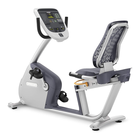
RBK 815 Recumbent Cycle
RBK 815 Bicycle
Warning: This service manual is for use by Precor trained service providers only.
If you are not a Precor Trained Servicer, you must not attempt to service any Precor
Product; Call your dealer for service.
This document contains information required to perform the majority of
troubleshooting, and replacement procedures required to repair and maintain this
product.
This document contains general product information, software diagnostic procedures
(when available), preventative maintenance procedures, inspection and adjustment
procedures, troubleshooting procedures, replacement procedures and electrical block
and wiring diagrams.
To move directly to a procedure, click the appropriate procedure in the bookmark
section to the left of this page. You may "drag" the separator bar between this page
and the bookmark section to change the size of the page being viewed.
Page 1
Advertisement
Table of Contents

Related Manuals for Precor RBK 815


Summary of Contents for Precor RBK 815
- Page 1 RBK 815 Bicycle Warning: This service manual is for use by Precor trained service providers only. If you are not a Precor Trained Servicer, you must not attempt to service any Precor Product; Call your dealer for service. This document contains information required to perform the majority of troubleshooting, and replacement procedures required to repair and maintain this product.
- Page 2 RBK 815 Recumbent Cycle © 2010 Precor Incorporated Unauthorized Reproduction and Distribution Prohibited By Law Page 2...
-
Page 3: Section One - Things You Should Know
To remove power from the RBK 815 the optional power adapter must be disconnected from the cycle. Always ensure that the optional power adapter is disconnected from the cycle when you inspect or adjust the RBK 815 or when you isolate, remove, or replace a component. -
Page 4: General Information
Do not use accessory attachments that are not recommended by the manufacturer, such attachments might cause injuries or damage to the unit. General Information For the latest exploded view diagram, part number and part pricing information, visit the Precor dealer website at “www.precor.com/connection”. Page 4... -
Page 5: Required Tools And Equipment
RBK 815 Recumbent Cycle Required Tools and Equipment The following is a summary of the tools and equipment that may be required when you service a Precor RBK 815 Upright Cycle. Tools Phillip and flat-head screwdrivers Standard and metric allen wrench set... -
Page 6: Section Two - Preventive Maintenance
Regular Preventive Maintenance (Owner) Cleanliness of the cycle and its operating environment will keep maintenance problems and service calls to a minimum. Precor recommends that you perform the following preventive maintenance schedule. After Each Use •... -
Page 7: Quarterly Maintenance
Check the belt tension of both belts per Procedures 5.1 and 5.2. Replace both covers. On-Site Preventive Maintenance (Service Technician) When you are called to service a RBK 815 perform these preventive maintenance activities: • Perform the software diagnostics. Check LED and keypad function. Record the odometer reading. -
Page 8: Procedure 3.1 - Accessing The Diagnostic Software
Machine Test Procedure Using the RESET key and the numeric keypad, press keys RESET,5,1,7,6,5,7,6,1, sequentially. Hardware Validation will scroll across the display followed by DISPLAY TEST. Diagram 3.1 - RBK 815 Display OK Key Numeric Keypad Clear key Reset Key... - Page 9 RBK 815 Recumbent Cycle Press the OK key, the upper most group of LED’s will illuminate on the display. Check the display to ensure that all LED segments are illuminated. Press the OK key four more times to display the remaining LED groups. Check each display group to ensure that all LED segments are illuminated.
-
Page 10: Procedure 3.2 - Information Display
Error Log Procedure Pedal the bicycle or install an optional external power supply. With the PRECOR banner scrolling, press the keys RESET,6,5, sequentially. DIAGS-INFORMATION DISPLAY will scroll across the display. Use the keys to move to the desired display shown in the list above. - Page 11 RBK 815 Recumbent Cycle U-BOOT SW display. This display the installed version of upper boot software. The boot software is used to upload new software into the upper display PCA. 12. Press the OK key. The software part number will be displayed as XXXXX-XXX.
-
Page 12: Procedure 3.3 - Selecting Club Settings
RBK 815 Recumbent Cycle Procedure 3.3 - Selecting Club Settings Procedure This procedure allows you to change the following club settings: • Select Language • Select Units • Set Max Workout Time • Set Max Pause Time • Set Cool Down Time •... - Page 13 RBK 815 Recumbent Cycle 19. Press the CLEAR key to exit the set cool down time display. 20. SET RESISTANCE RANGE display. Press the OK key. 21. Use the keys to select to HIGH, MEDIUM or LOW resistance range. 22. Press the CLEAR key to exit the set resistance range display.
-
Page 14: Procedure 3.4 - Documenting Software Problems
If you isolated the problem to either the PROM, upper PCA, or lower PCA, include the information you recorded with the malfunctioning PROM or PCA when you ship it to Precor. When a problem occurs, record the following information: •... -
Page 15: Section Four - Checking Operation
With the banner displayed, press QUICK START. Select Resistance Level 1 and press ENTER. Operate the RBK 815 for 4–5 minutes. As you operate the bike, concentrate on the operating sounds made by the unit. Be on the alert for unusual rubbing, hitting, grinding, or squeaking noises. -
Page 16: Procedure 5.1 - Primary Belt Tension Adjustment
RBK 815 Recumbent Cycle Procedure 5.1 - Primary Belt Tension Adjustment Remove the covers per Procedure 7.1 Place the belt tension gauge on the primary belt. The belt will twist when the tension gauge is engaged. The belt tensions have been adjusted to accommodate the twisting of the belt. - Page 17 RBK 815 Recumbent Cycle Diagram 5.2 - Primary Belt Adjustment Adjustment Bolt Adjustment Bracket Idler Pulley Mounting Nut Page 17...
- Page 18 RBK 815 Recumbent Cycle Turn the adjustment bolt clockwise or counter clockwise, as required, until the belt gauge is in the range of 90 pounds ± 5 pounds. Torque the idler pulley adjustment nut to 120 inch poinds (10 foot pounds).
-
Page 19: Procedure 5.2 - Secondary Belt Tension Adjustment
RBK 815 Recumbent Cycle Procedure 5.2 - Secondary Belt Tension Adjustment Remove the covers per Procedure 7.1. Place the belt tension gauge on the secondary belt. The belt will twist when the tension gauge is engaged. The belt tensions have been adjusted to accommodate the twisting of the belt. - Page 20 RBK 815 Recumbent Cycle Diagram 5.4 - Secondary Belt Adjustment Adjustment Bolt Replace the covers per Procedure 7.1. Page 20...
-
Page 21: Procedure 5.3 - Adjusting The Seat Carriage
RBK 815 Recumbent Cycle Procedure 5.3 - Adjusting the Seat Carriage Perform this procedure if the front to rear movement of the seat is too tight or there is excessive side to side seat wobble. Loosen but do not remove the four mounting screws on the left and right seat adjustment plates. -
Page 22: Procedure 6.1 - Display Does Not Illuminate
RBK 815 Recumbent Cycle Procedure 6.1 - Display does not Illuminate Note: In order to conserve battery power when the cycle is not in use, a time out feature is incorporated in the cycles software. If the cycle is not used (motion not detected by the speed sensor), when in the program mode, approximately 15 seconds later, the cycle will “power down”... - Page 23 RBK 815 Recumbent Cycle Diagram 6.1 - Lower PCA, RBK 815 M1, M2 M3, M4, M5 TP19 TP20 M6, M7 Page 23...
- Page 24 If the voltage is absent or significantly low, troubleshoot the interconnect cable. If the voltage measurement in step 4 is correct, replace the upper PCA. 10. If you have performed all of the previous tests and have not been able to locate the trouble, call Precor customer support. Page 24...
-
Page 25: Procedure 6.2 - No Or Incorrect Pedaling Resistance
Disconnect the eddy current magnet wires from terminals M1 and M2 of the lower PCA. Measure between the eddy current magnet wires with an ohmmeter. It should read approximately 10 W. Diagram 6.2 - Eddy Current Magnet, RBK 815 Generator Eddy Current Magnet If the measurement in step 5 was significantly high or low, replace the generator. - Page 26 RBK 815 Recumbent Cycle Procedure 6.3 - Troubleshooting the Keypad and Upper If the function keys on the electronic console are unresponsive, the problem may be either the upper PCA or keypad. WARNING Before continuing with this procedure, review the Warning and Caution statements listed in Section One.
- Page 27 RBK 815 Recumbent Cycle Diagram 6.3 - Upper PCA & Keypad Upper PCA Keypad Cable Metrics Cable D-Pad Cable Metrics PCA D-Pad Assembly D-Pad Clip Page 27...
- Page 28 The display front panel is equipped with the keypad. If you have performed all of the procedures above and have been unable to correct the problem, call Precor customer service. 10. Access the diagnostics program per procedure 3.1. If the key(s) necessary to access the diagnostic program is not functioning, skip to step 14.
-
Page 29: Procedure 6.6 - Troubleshooting Hand Held Heart Rate
RBK 815 Recumbent Cycle Procedure 6.6 - Troubleshooting Hand Held Heart Rate Circuit Description The hand held heart rate system is actually a dual system, that is, it can accept a heart rate signal from either the hand held heart rate contacts on the unit’s handlebar or from a Polar heart rate chest strap transmitter. - Page 30 RBK 815 Recumbent Cycle No hand held reading - Normal chest strap reading 4.Access the diagnostic program (Procedure 3.1). Advance to the heart rate display portion of the diagnostic program. Verify that a hand held signal is not being accepted by firmly grasping both the right and left hand held contacts on the handlebars.
- Page 31 RBK 815 Recumbent Cycle replace the heart rate PCA to handlebar wire harness. Page 31...
- Page 32 RBK 815 Recumbent Cycle No hand held reading - No chest strap reading 11.Access the diagnostic program (Procedure 3.1). Advance to the heart rate display portion of the diagnostic program. Verify that neither a chest strap signal or a hand held signal is being accepted with either a heart rate test transmitter or a chest strap transmitter.
-
Page 33: Procedure 7.1 - Replacing A Cover
Procedure 7.1 - Replacing a Cover Cover Removal Remove two screws, one each side, from the front of the top cover. Remove the top cover. See Diagram 7.1. Diagram 7.1 - RBK 815 Covers Top Cover Rear Cover Left Side Cover Remove three screws from the right side cover, remove the left side cover. - Page 34 RBK 815 Recumbent Cycle Slide the kick plate forward and remove it from the frame. Cover Replacement Set the kick plate in its mounting position on the frame and slide it back into place. Set the seat frame cover in its mounting position and fasten it with the screws removed in step 5, torque to 20 inch pounds.
-
Page 35: Procedure 7.2 - Replacing A Primary Belt
RBK 815 Recumbent Cycle Procedure 7.2 - Replacing a Primary Belt Remove the top, rear, left and right covers per procedure 7.1. Loosen but do not remove the idler pulley mounting nut. Loosen the primary belt tension adjustment bolt to remove tension from the primary belt. -
Page 36: Procedure 7.3 - Replacing A Secondary Belt
RBK 815 Recumbent Cycle Procedure 7.3 - Replacing a Secondary Belt Remove the top, rear, left and right covers per procedure 7.1. Loosen but do not remove the four generator mounting bolts. Remove tension from the secondary belt by loosening the secondary belt adjustment bolt mounted on the generator. -
Page 37: Procedure 7.4 - Replacing A Crankarm
RBK 815 Recumbent Cycle Procedure 7.4 - Replacing a Crankarm Using an 15mm open end wrench, remove the pedal from the crankarm being replaced. A Park Tool CCP-22 crankarm puller will be used to remove the crankarms. Diagram 7.6 - Park Tool CCP-22 Crankarm Puller Using an 8mm allen wrench, remove the crankarm mounting bolt. - Page 38 RBK 815 Recumbent Cycle Thread the crankarm mounting bolt, removed in step 2 into the crankarm until it is finger tight. Torque the crankarm bolt to 360 inch pounds (30 foot pounds). The right hand pedal threads onto the crankarm in a normal (clockwise) direction, the left hand crankarm is reverse (counter-clockwise) threaded.
-
Page 39: Procedure 7.5 - Replacing The Input Pulley
RBK 815 Recumbent Cycle Procedure 7.5 - Replacing the Input Pulley Remove the top, rear, left and right covers per procedure 7.1. Remove the right crankarm per Procedure 7.4. Loosen, but do not remove the idler pulley mounting nut. Remove tension from the primary belt by turning the primary belt tension adjustment bolt counter-clockwise. - Page 40 RBK 815 Recumbent Cycle 14. Replace the covers per Procedure 7.1. Page 40...
-
Page 41: Procedure 7.6 - Replacing The Input Axle Assembly
RBK 815 Recumbent Cycle Procedure 7.6 - Replacing the Input Axle Assembly Remove the top, rear, left and right covers per procedure 7.1. Remove both crankarms per Procedure 7.4. Loosen, but do not remove the idler pulley mounting nut. Remove tension from the primary belt by turning the primary belt tension adjustment bolt counter-clockwise. - Page 42 RBK 815 Recumbent Cycle tighten (counter-clockwise) the input pulley’s retaining nut. 17. Tension the primary belt per Procedure 5.1. 18. Replace the left crankarm per procedure 7.4. 19. Replace the covers per Procedure 7.1. Page 42...
-
Page 43: Procedure 7.7 - Replacing The Idler Pulley
RBK 815 Recumbent Cycle Procedure 7.7 - Replacing the Idler Pulley Remove the top, rear, left and right covers per procedure 7.1. Loosen, but do not remove the idler pulley mounting nut. Remove tension from the primary belt by turning the primary belt tension adjustment bolt counter-clockwise. -
Page 44: Procedure 7.8 - Replacing The Secondary Sheave
RBK 815 Recumbent Cycle Procedure 7.8 - Replacing the Secondary Sheave Remove the top, rear, left and right covers per procedure 7.1. Loosen, but do not remove the idler pulley mounting nut. Remove tension from the primary belt by turning the primary belt tension adjustment bolt counter-clockwise. -
Page 45: Procedure 7.9 - Replacing The Secondary Pulley
RBK 815 Recumbent Cycle Procedure 7.9 - Replacing the Secondary Pulley Remove the top, rear, left and right covers per procedure 7.1. Loosen, but do not remove the generator screws and tension bracket mounting bolt, thread the tension adjustment bolt counter-clockwise to remove tension from the secondary belt. -
Page 46: Procedure 7.10 - Replacing The Secondary Axle Assembly
RBK 815 Recumbent Cycle Procedure 7.10 - Replacing the Secondary Axle Assembly Remove the top, rear, left and right covers per procedure 7.1. Loosen, but do not remove the idler pulley mounting nut. Remove tension from the primary belt by turning the primary belt tension adjustment bolt counter-clockwise. -
Page 47: Procedure 7.11 - Replacing A Generator
RBK 815 Recumbent Cycle Procedure 7.11 - Replacing a Generator Remove the top, rear, left and right covers per procedure 7.1. Disconnect the two generator cables from the lower PCA. The cables are connected to M1, M2 and M3, M4, M5 on the lower PCA. See Diagram 6.1. Remove the generator clips from their cable retaining clips. - Page 48 RBK 815 Recumbent Cycle inch pounds. 14. Reconnect the two generator cables, removed in step 2 to the lower PCA. Connect the two red magnet wires to terminals M1 & M2, the order does not matter. Connect the red generator wire to M3, the white generator wire to M4 and the black generator wire to M5.
-
Page 49: Procedure 7.12 - Replacing A Battery
RBK 815 Recumbent Cycle Procedure 7.12 - Replacing a Battery Remove the top rear, top main and left side covers per Procedure 7.1. The battery is held in place by the covers. Remove the red and black wires from the battery. -
Page 50: Procedure 7.13 - Replacing The Lower Pca
RBK 815 Recumbent Cycle Procedure 7.13 - Replacing the Lower PCA Remove the top, rear, left and right covers per procedure 7.1. Disconnect all of the wires from the lower PCA. Remove the four screws that fasten the lower PCA. Remove and discard the lower PCA. - Page 51 RBK 815 Recumbent Cycle Procedure 7.14 - Replacing a Display Front Panel, Upper PCA, Metrics PCA or HR PCA The keyboard is part of the display front panel front panel. If the keyboard is not functioning properly, replace the display front panel front panel.
- Page 52 RBK 815 Recumbent Cycle replacement procedure as required. Removing and Replacing the Upper PCA Carefully disconnect the keyboard cable from the upper PCA. See Diagram 6.3. Disconnect the cables from the metrics PCA and the and the D-pad PCA. See Diagram 6.3.
- Page 53 RBK 815 Recumbent Cycle Replacing a D-Pad Assembly 23. Disconnect the D-pad cable from the D-pad assembly. See Diagram 6.3. 24. Unsnap the D-pad assembly from the display front panel and discard. 25. Place the replacement D-pad assembly in its mounting position on the display front panel and snap it into place.
-
Page 54: Procedure 7.15 - Replacing All Or Part Of A Seat Carriage
RBK 815 Recumbent Cycle Procedure 7.15 - Replacing All or Part of a Seat Carriage Removing the Seat Carriage There is a heart rate cable that connects the heart rate hand grips in the seat carriage to the hear rate cable in the seat rail. Care must be taken when removing the seat carriage to avoid damaging the heart rate cables. - Page 55 RBK 815 Recumbent Cycle Diagram 7.17 - Heart Rate Cables and Cover Cable Clamp Disconnect Here Replacing Seat Carriage Heart Rate Cables On the underside of the seat carriage, remove the cable cover and disconnect the flat ribbon cable from the cable to the heart rate grips. See Diagram 7.18.
- Page 56 RBK 815 Recumbent Cycle rate grip access hole and the black wire out of the lower heart rate grip access hole. 10. On both handlebars, connect the upper heart rate grip to the red wire and the lower handlebar grip to the black wire. Torque screws to 8 inch pounds.
- Page 57 RBK 815 Recumbent Cycle 90 inch pounds. Replacing the Seat Carriage Assembly 19. Slide the seat carriage partially onto the seat rail. 20. Slide the seat carriage fully onto the seat rail and all the way forward. Set seat stop in its mounting position. Replace the end cap and fasten it to the seat stop with the hardware removed in step 3.
-
Page 58: Wiring Diagram 8.1 - Rbk 815
RBK 815 Recumbent Cycle Wiring Diagram 8.1 - RBK 815 HHHR Grips HHHR Grips Optional A.C. Adapter Page 58... -
Page 59: Block Diagram 8.2 - Rbk 815
RBK 815 Recumbent Cycle Block Diagram 8.2 - RBK 815 Page 59...
Need help?
Do you have a question about the RBK 815 and is the answer not in the manual?
Questions and answers