Sign In
Upload
Manuals
Brands
General Monitors Manuals
Security Sensors
FL4000H
General Monitors FL4000H Manuals
Manuals and User Guides for General Monitors FL4000H. We have
1
General Monitors FL4000H manual available for free PDF download: Quick Start Manual
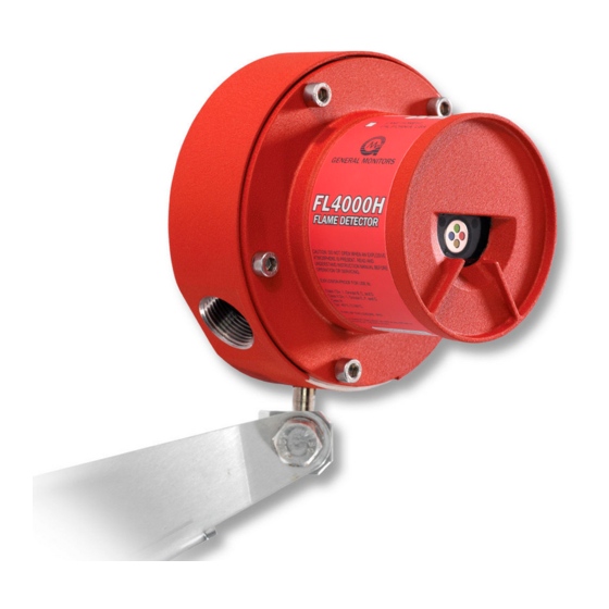
General Monitors FL4000H Quick Start Manual (72 pages)
Multi-Spectral Infrared Flame Detector
Brand:
General Monitors
| Category:
Security Sensors
| Size: 1 MB
Table of Contents
Multi-Spectral Infrared
1
Table of Contents
3
Flame Detector
1
Table of Figures
5
Quick Start Guide
7
Mounting and Wiring the Detector
7
Figure 1: FL4000H Housing
7
Figure 2: Mounting Instruction
8
Figure 3: Wall Mounting Assembly
8
Applying Power to the Detector
9
Figure 4: Bracket Assembly
9
Figure 5: Field Terminations Showing Wiring for Fire Alarm Systems
9
Testing the Detector Using a Test Lamp
10
About this Manual
10
Format Conventions
10
Other Sources of Help
10
1 0 before Installation
11
System Integrity Verification
11
Commissioning Safety Systems
11
Special Warnings
11
Glossary of Terms
12
Table 1: Glossary of Terms
12
2 0 Product Overview
14
General Description
14
Features and Benefits
14
Figure 6: FL4000H Front View
14
Applications
15
Principle of Operation
15
Table 2: Sample Industry Applications
15
Table 3: LED Sequence for each Operating Condition
16
Figure 7: Test Lamp Flashing Option (Auto-Detection)
19
Figure 8: Grounding of Test Wire or Modbus Command Options
20
3 0 Installation
21
Unpacking the Equipment
21
Required Tools
21
Table 4: Required Tools
21
Detector Location Guidelines
22
Table 5: Maximum Specified Fields of View at High Sensitivity
22
Figure 9: Horizontal FOV - N-Heptane - High Sensitivity
23
Figure 10: Horizontal FOV - N-Heptane - Medium Sensitivity
23
Figure 11: Horizontal FOV - N-Heptane - Low Sensitivity
24
Figure 12: Vertical FOV - N-Heptane - High Sensitivity
24
Figure 13: Vertical FOV - N-Heptane - Medium Sensitivity
25
Figure 14: Vertical FOV - N-Heptane - Low Sensitivity
25
Table 6: Sensitivity Settings for N-Heptane
25
Field Wiring Procedure
26
Figure 15: FL4000H Housing
26
Detector Mounting and Installation
27
Figure 16: Detector Mounting and Installation
28
Terminal Connections
29
Figure 17: Dimensional Drawing
29
Figure 18: Wire-Strip Lengths
29
Figure 19: Base Housing and Terminal Blocks
30
Table 7: Terminal Block Connections
30
Figure 20: Terminal Connections
31
Table 8: Alarm Relay Terminals
31
Figure 21: Relay Contacts
32
Table 9: Warning Relay Terminals
32
Table 10: Fault Relay Terminals
33
Table 11: Alarm Reset Terminal
33
Table 12: Test Mode Terminal
33
Figure 22: Wiring Diagram - Reset Relays, Test Mode, & Alarm Test
34
Table 13: Alarm Test Terminals
34
Table 14: Analog Output Terminal
34
Table 15: Analog Output Levels
35
Table 16: Maximum Cable Lengths for 250 Inputs
35
Table 17: Power Terminals
35
Table 18: Maximum Cable Lengths for +24 VDC
35
Switch Selectable Options
36
Table 19: Modbus Terminals
36
Table 20: Chassis Ground Terminal
36
Figure 23: Dipswitch Location
37
Table 21: Dipswitch Options
37
Powering of the FL4000H
38
Power up Grounding of the Test and Relay Reset Lines
38
4 0 Modbus Interface
39
Introduction
39
Communication Slave Address
39
Baud Rate
39
Data Format
39
Table 22: Selectable Baud Rates
39
Table 23: Selectable Data Formats
39
Supported Function Codes
40
Modbus Read Status Protocol (Query / Response)
40
Table 24: Modbus Read Register(S) Request
40
Table 25: Modbus Read Register(S) Response
40
Modbus Write Command Protocol (Query / Response)
41
Exception Responses and Exception Codes
41
Table 26: Modbus Write Register Request
41
Table 27: Modbus Write Register Response
41
Table 28: Exception Response
42
Table 29: Exception Codes
42
Command Register Locations
43
Table 30: Command Register Locations
43
Command Register Details
47
Table 31: Status Mode Values
47
Table 32: Modbus Error Codes
48
Figure 24: Command Register
49
Table 33: Com1 Baud Rate
50
Table 34: Selectable Data Formats
50
Table 35: Event Log Clock Time Format
54
5 0 Maintenance
58
General Maintenance
58
Cleaning the Sapphire Window
58
Figure 25: Optical Parts to Clean
58
Sensitivity Check
59
Storage
59
6 0 Troubleshooting
60
Troubleshooting Chart
60
Table 36: Troubleshooting Chart
60
Final Assembly
61
Figure 26: FL4000H Cross-Section View
61
7 0 Customer Support
62
Other Sources of Help
62
Table 37: Locations
62
8 0 Appendix
63
Warranty
63
Specifications
63
Regulatory Information
65
Response to False Stimuli
66
Table 38: False Alarm Immunity at High Sensitivity
66
Spare Parts and Accessories
67
Table 39: Flame Response in the Presence of False Alarm Sources (High Sensitivity)
67
Table 40: List of Spare Parts
68
Figure 27: Rain Guard Installation
69
Figure 28: Functional Board Located under TL105 Lamp Assembly
70
Appendix A
70
Advertisement
Advertisement
Related Products
General Monitors FL4000
General Monitors FL3100
General Monitors FL3101
General Monitors FL3112
General Monitors FL3102
General Monitors FL3110
General Monitors FL3111
General Monitors FL3101H
General Monitors IR400
General Monitors IR5500
General Monitors Categories
Security Sensors
Accessories
Control Unit
Monitor
Measuring Instruments
More General Monitors Manuals
Login
Sign In
OR
Sign in with Facebook
Sign in with Google
Upload manual
Upload from disk
Upload from URL