Table of Contents
Advertisement
Advertisement
Table of Contents
Troubleshooting

Related Manuals for Nilfisk-Advance BA 450


Summary of Contents for Nilfisk-Advance BA 450
- Page 1 BA 450/530 BA 5321 SERVICE MANUAL 08812876(1)2002-01...
- Page 2 Nilfisk-Advance Italia S.p.A Località Novella Terza 26862 Guardamiglio (Lodi) Italia www.nilfisk-advance.com Phone: +39 0377 451124 Fax: +39 0377 51443 Printed in Italy...
-
Page 3: Table Of Contents
SERVICE MANUAL INDEX GENERAL INFORMATION MACHINE LIFTING MACHINE TRANSPORTATION MACHINE PUSHING OR TOWING OTHER AVAILABLE MANUALS FOR BA 450/530 SAFETY - ACCIDENT PREVENTION GENERAL SAFETY RULES TECHNICAL DATA MAINTENANCE SCHEDULED MAINTENANCE MACHINE NOMENCLATURE DETERGENT SUPPLY SYSTEM DETERGENT TANK AND SUPPLY SYSTEM CLEANING... - Page 4 TRACTION ELECTRONIC BOARD REPLACEMENT ELECTRICAL SYSTEM SERVICE ELECTRONIC BOARD REPLACEMENT TROUBLESHOOTING COMPONENT LAYOUT WIRING DIAGRAM BA 450/530 - after serial number 014106978 WIRING DIAGRAM BA 5321 - after serial number 1514570 WIRING DIAGRAM BA 5321D - after serial number 1514570 08812876(1)2002-01...
-
Page 5: General Information
OTHER AVAILABLE MANUALS FOR BA 450/530 The following manuals are available by Nilfisk Literature Service Department: – BA 450/530 Part List – Nilfisk Form Number 08603654(2)00-12 – BA 450/530 Use and Maintenance Manual.- Nilfisk Form Number 08812382(2)2001-03 08812876(1)2002-01... -
Page 6: Safety - Accident Prevention
SERVICE MANUAL GENERAL INFORMATION SAFETY - ACCIDENT PREVENTION Nilfisk uses the following symbols to indicate potentially dangerous situations. Always read carefully this information and take the necessary precautions to protect people and objects. DANGER! Indicates the risk of being injured or the risk of death. WARNING! Indicates the risk of being injured. -
Page 7: Technical Data
200 W - 120 RPM 200 W - 120 RPM 200 W - 120 RPM Dirty water suction pressure 13 kPa 13 kPa 13 kPa Air intake 31 l/sec 31 l/sec 31 l/sec (*) BA 450/530 with traction motor only 08812876(1)2002-01... - Page 8 SERVICE MANUAL GENERAL INFORMATION BA 450 = 1250 BA 530 / CA 5321 = 1330 S300161 Dimensions expressed by mm 08812876(1)2002-01...
-
Page 9: Maintenance
SERVICE MANUAL GENERAL INFORMATION MAINTENANCE SCHEDULED MAINTENANCE The machine proper and safe operation is granted by a careful and constant maintenance. See GENERAL INFORMATION and SAFETY - ACCIDENT PREVENTION The following table sums up the scheduled maintenance. The indicated periods can be subjected to variations according to working conditions. -
Page 10: Machine Nomenclature
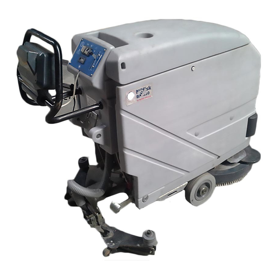
Suction motor Brush reduction unit Brush motor Suction cap balancing adjustment handwheel Traction adjusting handles Traction switch (*) Brush Integrated battery charger (**) (*) BA 450/530 with traction motor only Circuit panel (**) Optional Traction motor (*) Batteries S300162 08812876(1)2002-01... - Page 11 SERVICE MANUAL GENERAL INFORMATION MACHINE NOMENCLATURE (CONTINUE) S300163 08812876(1)2002-01...
-
Page 12: Detergent Supply System
SERVICE MANUAL DETERGENT SUPPLY SYSTEM DETERGENT TANK AND SUPPLY SYSTEM CLEANING DETERGENT SUPPLY SYSTEM Empty the detergent tank (14) through the pipe (26). Take the detergent flow control lever (6) in wide-open position, then activate the machine until the detergent inside the machine is exhausted. -
Page 13: Solenoid Valve And Detergent Flow Tap Replacement
SERVICE MANUAL DETERGENT SUPPLY SYSTEM SOLENOID VALVE AND DETERGENT FLOW TAP REPLACEMENT Drive the machine on a level ground. Turn the switch key (2) to OFF position. If there is recovery water in the tank (11) remove it through the pipe (25). If there is detergent in the tank (14) remove it through the pipe (26). -
Page 14: Detergent Flow Cable And Control Lever Replacement
SERVICE MANUAL DETERGENT SUPPLY SYSTEM DETERGENT FLOW CABLE AND CONTROL LEVER REPLACEMENT Drive the machine on a level ground. Turn the switch key (2) to OFF position. Operating under the machine left side, loosen the sheath (D) fixing clamp (C) and disconnect the cable (A) from the tap lever (B). -
Page 15: Troubleshooting
SERVICE MANUAL DETERGENT SUPPLY SYSTEM TROUBLESHOOTING SMALL AMOUNT OF THE DETERGENT OR NO DETERGENT REACHES THE BRUSH Possible cause: The brush switch (3) is not to ON position or it is broken (turn it on or repair/replace it). The detergent filter is obstructed/dirty (clean it). The detergent flow control lever does not control the related tap anymore (check the control lever cable, from the lever to the tap). -
Page 16: Sweeping System
SERVICE MANUAL SWEEPING SYSTEM BRUSH MOTOR ELECTRICAL INPUT CHECK SWEEPING SYSTEM WARNING! This procedure must be performed by qualified personnel only. Remove the brush (18). Drive the machine on a level ground. Turn the switch key (2) to OFF position. If there is recovery water in the tank (11) remove it through the pipe (25). -
Page 17: Brush Motor Replacement
SERVICE MANUAL SWEEPING SYSTEM BRUSH MOTOR REPLACEMENT Remove the brush (18). Drive the machine on a level ground. Turn the switch key (2) to OFF position. If there is recovery water in the tank (11) remove it through the pipe (25). If there is detergent in the tank (14) remove it through the pipe (26). -
Page 18: Brush Reduction Unit Replacement
SERVICE MANUAL SWEEPING SYSTEM BRUSH REDUCTION UNIT REPLACEMENT Remove the brush (18). Drive the machine on a level ground. Remove the suction cap (see the related paragraph). Turn the switch key (2) to OFF position. If there is recovery water in the tank (11) remove it through the pipe (25). If there is detergent in the tank (14) remove it through the pipe (26). - Page 19 SERVICE MANUAL SWEEPING SYSTEM BRUSH REDUCTION UNIT REPLACEMENT (Continue) Figure 7 S300174 08812876(1)2002-01...
-
Page 20: Brush Rotation Consent Micro-Switch Adjustment
SERVICE MANUAL SWEEPING SYSTEM BRUSH ROTATION CONSENT MICRO-SWITCH ADJUSTMENT Drive the machine on a level ground. Turn the switch key (2) to OFF position. If there is recovery water in the tank (11) remove it through the pipe (25). If there is detergent in the tank (14) remove it through the pipe (26). Remove the key (28) from its housing and remove the tank assembly fastening screw (29). -
Page 21: Troubleshooting
SERVICE MANUAL SWEEPING SYSTEM TROUBLESHOOTING OPEN CIRCUIT The thermal fuse (35) determines the open circuit. This system allows to prevent the brush motor circuits from being damaged under overload conditions. If there is an open in the electrical circuit, the possible causes are the following. Brush motor;... -
Page 22: Recovery System
SERVICE MANUAL RECOVERY SYSTEM FLOAT SHIELD AND SUCTION PRE-FILTER CLEANING RECOVERY SYSTEM Drive the machine on a level ground. Turn the switch key (2) to OFF position. Lift the cover (24) of the tanks. If necessary drain the water from the recovery tank (11) through the pipe (25) to visually inspect the shield (A). -
Page 23: Suction Pre-Filter Assembly Replacement
SERVICE MANUAL RECOVERY SYSTEM SUCTION PRE-FILTER ASSEMBLY REPLACEMENT Drive the machine on a level ground. Turn the switch key (2) to OFF position. Lift the cover (24) of the tanks. Drain all the water from the recovery tank (11) through the pipe (25). Disengage the retainers (A) and open the shield (B) by disengaging it from the pre-filter assembly. -
Page 24: Tank Cover Gasket And Compensation Hole Check
SERVICE MANUAL RECOVERY SYSTEM TANK COVER GASKET AND COMPENSATION HOLE CHECK Drive the machine on a level ground. Turn the switch key (2) to OFF position. Lift the cover (24) of the tanks. Check that the tank cover gasket (A) is clean. Remark: The gasket (A) creates suction pressure that is necessary for the suction of recovery water. -
Page 25: Suction Motor Electrical Input Check
SERVICE MANUAL RECOVERY SYSTEM SUCTION MOTOR ELECTRICAL INPUT CHECK WARNING! This procedure must be performed by qualified personnel only. Drive the machine on a level ground. Turn the switch key (2) to OFF position. If there is recovery water in the tank (11) remove it through the pipe (25). If there is detergent in the tank (14) remove it through the pipe (26). -
Page 26: Suction Motor Removal
SERVICE MANUAL RECOVERY SYSTEM SUCTION MOTOR REMOVAL Drive the machine on a level ground. Turn the switch key (2) to OFF position. If there is recovery water in the tank (11) remove it through the pipe (25). If there is detergent in the tank (14) remove it through the pipe (26). Remove the key (28) from its housing and remove the tank assembly fastening screw (29). -
Page 27: Suction Motor Brush/Carbon Brush Check And Replacement
SERVICE MANUAL RECOVERY SYSTEM SUCTION MOTOR BRUSH/CARBON BRUSH CHECK AND REPLACEMENT Drive the machine on a level ground. Turn the switch key (2) to OFF position. If there is recovery water in the tank (11) remove it through the pipe (25). If there is detergent in the tank (14) remove it through the pipe (26). -
Page 28: Recovery Water Drain Pipe Removal
SERVICE MANUAL RECOVERY SYSTEM RECOVERY WATER DRAIN PIPE REMOVAL Drive the machine on a level ground. Turn the switch key (2) to OFF position. If there is recovery water in the tank (11) remove it through the pipe (25). If there is detergent in the tank (14) remove it through the pipe (26). Remove the retaining flange (A) inside the tank (11). -
Page 29: Suction Cap Check/Cleaning And Possible Flaps Replacement
SERVICE MANUAL RECOVERY SYSTEM SUCTION CAP CHECK/CLEANING AND POSSIBLE FLAPS REPLACEMENT RECOVERY SYSTEM Drive the machine on a level ground. Turn the switch key (2) to OFF position. Lower the suction cap assembly (23) by means of the handle (9). Disconnect the suction pipe (A) from the suction cap (C) and from the tank (Q);... -
Page 30: Dust And Debris Collection System Suction Cap Removal
SERVICE MANUAL RECOVERY SYSTEM SUCTION CAP CHECK/CLEANING AND POSSIBLE FLAPS REPLACEMENT RECOVERY SYSTEM (Continue) Figure 10 S300186 DUST AND DEBRIS COLLECTION SYSTEM SUCTION CAP REMOVAL SISTEMA DI RACCOLTA DETRITI E POLVERE Drive the machine on a level ground. Turn the switch key (2) to OFF position. Lower the suction cap assembly (23) by means of the handle (9). -
Page 31: Troubleshooting
SERVICE MANUAL RECOVERY SYSTEM TROUBLESHOOTING RECOVERY SYSTEM OPEN CIRCUIT The thermal fuse (36) determines the open circuit. This system allows to prevent the suction motor circuits from being damaged under overload conditions. If there is an open in the electrical circuit, the possible causes are the following. Suction motor;... -
Page 32: Traction System
SERVICE MANUAL TRACTION SYSTEM TRACTION MOTOR ELECTRICAL INPUT CHECK TRACTION SYSTEM WARNING! This procedure must be performed by qualified personnel only. Drive the machine on a level ground. Turn the switch key (2) to OFF position. If there is recovery water in the tank (11) remove it through the pipe (25). If there is detergent in the tank (14) remove it through the pipe (26). - Page 33 SERVICE MANUAL TRACTION SYSTEM TRACTION MOTOR ELECTRICAL INPUT CHECK (Continue) Figure 1 S300188 Figure 2 S300189 08812876(1)2002-01...
-
Page 34: Traction Motor Removal
SERVICE MANUAL TRACTION SYSTEM TRACTION MOTOR REMOVAL Remove the brush (18). Drive the machine on a level ground. Remove the suction cap (see the related paragraph). Turn the switch key (2) to OFF position. If there is recovery water in the tank (11) remove it through the pipe (25). If there is detergent in the tank (14) remove it through the pipe (26). - Page 35 SERVICE MANUAL TRACTION SYSTEM TRACTION MOTOR REMOVAL (Continue) Figure 4 S300191 Figure 5 S300192 08812876(1)2002-01...
-
Page 36: Traction Motor Brush (Or Carbon Brush) Check And Replacement
SERVICE MANUAL TRACTION SYSTEM TRACTION MOTOR BRUSH (OR CARBON BRUSH) CHECK AND REPLACEMENT Remove the brush (18). Drive the machine on a level ground. Remove the suction cap (see the related paragraph). Turn the switch key (2) to OFF position. If there is recovery water in the tank (11) remove it through the pipe (25). - Page 37 SERVICE MANUAL TRACTION SYSTEM TRACTION MOTOR BRUSH (OR CARBON BRUSH) CHECK AND TRACTION SYSTEM REPLACEMENT (Continue) Figure 7 S300194 08812876(1)2002-01...
-
Page 38: Potentiometer Adjustment
SERVICE MANUAL TRACTION SYSTEM POTENTIOMETER ADJUSTMENT Drive the machine on a level ground. Turn the switch key (2) to OFF position. If there is recovery water in the tank (11) remove it through the pipe (25). If there is detergent in the tank (14) remove it through the pipe (26). Remove the key (28) from its housing and remove the tank assembly fastening screw (29). -
Page 39: Troubleshooting
SERVICE MANUAL TRACTION SYSTEM TROUBLESHOOTING OPEN CIRCUIT Possible cause: There are bulky debris or cords under the machine or around the driving wheels (remove the debris). The motor is damaged (check the motor brushes/electrical input). The slope is excessive (drive only on the maximum slope allowed) Wait at least 2 minutes after the break and, when the problem is solved, push the thermal fuse button (34). -
Page 40: Electrical System
SERVICE MANUAL ELECTRICAL SYSTEM BATTERY REMOVAL ELECTRICAL SYSTEM Drive the machine on a level ground. Turn the switch key (2) to OFF position. If there is recovery water in the tank (11) remove it through the pipe (25). If there is detergent in the tank (14) remove it through the pipe (26). Remove the key (28) from its housing and remove the tank assembly fastening screw (29). -
Page 41: Electrical System
SERVICE MANUAL ELECTRICAL SYSTEM SERVICE ELECTRONIC BOARD REPLACEMENT ELECTRICAL SYSTEM REMARK: It is not necessary to perform the electronic programming of the new board. Remove the batteries (See the previous procedure). Remove the screws (A) and the electronic case cover (B). Disconnect all the electrical connections of the board (C) (See the wiring diagram). -
Page 42: Troubleshooting
SERVICE MANUAL ELECTRICAL SYSTEM TROUBLESHOOTING See the previous chapters related to the use of the electrical system. Other possible malfunction causes are: The battery is discharged or its connections are not efficient (charge the battery or clean the connections). The battery charger is not efficient (replace it). The thermal fuses are deactivated (activate them). - Page 43 SERVICE MANUAL ELECTRICAL SYSTEM Figure 3 S300198 08812876(1)2002-01...
-
Page 44: Wiring Diagram Ba 450/530 - After Serial Number 014106978
SERVICE MANUAL ELECTRICAL SYSTEM WIRING DIAGRAM BA 450/530 - after serial number 014106978 With traction with battery charger 08812796 S300199 08812876(1)2002-01... - Page 45 SERVICE MANUAL ELECTRICAL SYSTEM WIRING DIAGRAM BA 450/530 - after serial number 014106978 Without traction with battery charger 08812797 S300200 08812876(1)2002-01...
- Page 46 SERVICE MANUAL ELECTRICAL SYSTEM WIRING DIAGRAM BA 450/530 - after serial number 014106978 With traction without battery charger 08812798 S300201 08812876(1)2002-01...
- Page 47 SERVICE MANUAL ELECTRICAL SYSTEM WIRING DIAGRAM BA 450/530 - after serial number 014106978 Without traction without battery charger 08812799 S300202 08812876(1)2002-01...
-
Page 48: Wiring Diagram Ba 5321 - After Serial Number 1514570
SERVICE MANUAL ELECTRICAL SYSTEM WIRING DIAGRAM BA 5321 - after serial number 1514570 S300203 08812876(1)2002-01... -
Page 49: Wiring Diagram Ba 5321D - After Serial Number 1514570
SERVICE MANUAL ELECTRICAL SYSTEM WIRING DIAGRAM BA 5321D - after serial number 1514570 S300204 08812876(1)2002-01... - Page 50 SERVICE MANUAL ELECTRICAL SYSTEM FINE 08812876(1)2002-01...
- Page 51 Nilfisk-Advance, Inc. 14600 21st Avenue North Plymouth, MN, 55447-3408 www.nilfisk-advance.com Phone: 800-989-2235 Fax: 800-989-6566 ©2002 Nilfisk-Advance, Inc., Plymouth, MN 55447-3408 Printed in the U.S.A.
Need help?
Do you have a question about the BA 450 and is the answer not in the manual?
Questions and answers