Jacobsen AR3 Safety, Operation And Maintenance Manual
Hide thumbs
Also See for AR3:
- Technical/repair manual (342 pages) ,
- Safety, operation and maintenance manual (168 pages) ,
- Operation manual (148 pages)
Table of Contents
Advertisement
Available languages
Available languages
Quick Links
Safety, Operation and Maintenance Manual
Veiligheids-, Bedienings- & Onderhoudshandleiding
Jacobsen AR3, Kubota D1105-E4B
Jacobsen AR3, Kubota D1105-E3B
Series / Serie: EK
Product code / Productcode: AR30001
Series / Serie: FZ
Product code / Productcode: AR30002
Series / Serie: GX
Product code / Productcode: AR30003
Series / Serie: KG
Product code / Productcode: AR30004
WARNING: If incorrectly used this machine can cause
severe injury. Those who use and maintain this
machine must be trained in its proper use, warned of
its dangers and must read the entire manual before
attempting to set up, operate, adjust or service the
machine.
WAARSCHUWING
WAARSCHUWING: Bij onjuist gebruik kan deze
machine ernstig letsel veroorzaken. Degenen, die
deze machine gebruiken en onderhouden, moeten
getraind zijn in de juiste bediening, gewezen zijn op
de
gevaren
en
bedieningshandleiding te hebben gelezen, alvorens
pogingen te ondernemen de machine in te stellen, te
bedienen, af te stellen of onderhoud aan de machine
WARNING: If incorrectly used this machine can cause
te plegen.
severe injury. Those who use and maintain this machine
should be trained in its proper use, warned of its dangers and
should read the entire manual before attempting to set up,
operate, adjust or service the machine.
RJL 100 September 2014
NL
Netherlands
WARNING
dienen
de
gehele
24715G-NL (R6)
Advertisement
Table of Contents

Related Manuals for Jacobsen AR3


Summary of Contents for Jacobsen AR3
- Page 1 24715G-NL (R6) Safety, Operation and Maintenance Manual Veiligheids-, Bedienings- & Onderhoudshandleiding Jacobsen AR3, Kubota D1105-E4B Jacobsen AR3, Kubota D1105-E3B Series / Serie: EK Product code / Productcode: AR30001 Series / Serie: FZ Product code / Productcode: AR30002 Series / Serie: GX...
-
Page 2: Table Of Contents
Fitting The Cutting Units To The Machine ......34 Torques ................82 Starting The Engine ............35 Driving ................35 GUARANTEE Mowing ................35 Warranty ................83 To Stop The Engine ............35 Service ................83 © Ransomes Jacobsen Limited. All Rights Reserved... -
Page 3: Introduction 2
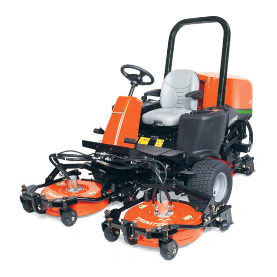
INTRODUCTION 2 The Jacobsen AR3 is a Diesel engined self propelled Rotary mower. The hydraulic systems are for the traction drive, the cutting unit lift and the lower and cutting unit drives and steering. IMPORTANT: The reliability and cutting performance of this machine will depend on the its care and use. -
Page 4: Product Identification
2 INTRODUCTION PRODUCT IDENTIFICATION Maximum front axle load in Kg (for machines being driven on West Road the highway) Ransomes Europark Ipswich IP3 9TT Gross weight (mass) in Kg England Maximum rear axle load in Kg (for machines being driven on the highway) Power in Kw Date code... - Page 5 INTRODUCTION 2 ROPS Serial Plate LMAC 164 MADE IN U.K. A.B.T. PRODUCTS LTD. ROSS-ON-WYE, HEREFORDSHIRE, HR9 7BW TEL: (01989) 563653 ### - ## ROPS Serial Plate Location The ROPS serial plate (C) is located at the base of the of the ROPS main left hand beam.
-
Page 6: Guidelines For The Disposal Of Scrap Products
“General discarded materials” area. • Do not burn discarded materials. Change the machinery records to show that the machine is not in service and is discarded. Supply this serial number to Ransomes Jacobsen Warranty Department to close their records. en-6... -
Page 7: Parts Manual
INTRODUCTION 2 PARTS MANUAL In compliance with the ISO14001 standard, Ransomes Jacobsen Limited does not send a paper parts manual with every product. To refer to a parts list for this mower you have four options: Website – www.RansomesJacobsen.com. Select the “GENUINE PARTS” tab followed by the “ONLINE PARTS LOOK-UP”... -
Page 8: Safety
Manuals in additional languages may be available on the Jacobsen or RansomesJacobsen website. Read all of the instructions for this mower carefully. Know the controls and the correct operation of the equipment. -
Page 9: Operation
SAFETY 3 3.1.3 Operation Never operate the engine without enough ventilation or in an enclosed area. The carbon monoxide in the exhaust fumes can increase to dangerous levels. Never carry passengers. Keep other persons or animals away from the mower. Disengage all drives and engage the parking brake before you start the engine. -
Page 10: Rops
ROPS. Do not remove the ROPS from the mower. Jacobsen must approve any changes to the ROPS. 3.1.5 Safe Handling of Fuels The fuel and the fuel vapors are flammable. Use caution when you add the fuel to the mower. The fuel vapors can cause an explosion. -
Page 11: When You Put A Mower On A Trailer
Keep all nuts, bolts and screws tight to make sure the equipment is in safe condition. Replace worn or damaged parts for safety. Replace damaged or worn decals. Only use parts, accessories and attachments approved by Jacobsen. To decrease the fire hazard, remove materials that burn from the engine, muffler, battery tray and fuel tank area. -
Page 12: Important Safety Notes
By following all instructions in this manual, you increase the life of your machine and keep its maximum performance. Adjustments and maintenance must always be done by an approved technician. If additional information or service is needed. Contact your Authorized Ransomes Jacobsen Dealer, who knows the latest methods to service this equipment and can give that service. - Page 13 2006/42/EC Sections 3.2.2, Seating & 3.4.3, Rollover. (ANSI B71.4-2012 section 20.7) Ransomes Jacobsen Limited Recommends That The Owner/User Of The Machine Completes A Local Risk Assessment Of The Machine To Find Any Conditions That Do Not Follow This Rule. E.g. When You Drive The Machine Next To Water Or On The Highway.
- Page 14 3 SAFETY WARNING Vibration Exposure Limits Exposure limits are calculated as a combination of the vibration level (magnitude) of the tool and the Daily Exposure Time (Trigger Time). E.g. A product with 5m/s² vibration can be used up to 2 hours/day to reach the EAV and up to 8 hours/day to reach the ELV.
-
Page 15: Specifications
SPECIFICATION 4 ENGINE SPECIFICATION Transmission: 3-wheel drive. Direct coupled variable displacement pump to Tier 4 Engine: Kubota 18.5KW (24.8HP) @ direct coupled 200cc/rev front, 3000 RPM, 3 cylinder (in line) 400cc/rev rear wheel motor. Normally Aspirated Diesel Speeds: engine, 4 stroke, water cooled, Cutting: 0 - 9.5 km/h (0 - 5.9 mph) FORWARD... -
Page 16: Vibration Level
4 SPECIFICATION VIBRATION LEVEL The machine was tested for hand/arm vibration levels. The operator was in the normal position to drive the vehicle, with two hands on the steering mechanism. The engine was in operation and the cutting device was in rotation, while the machine was not moving. -
Page 17: Noise Emissions
SPECIFICATION 4 NOISE Emissions When the machine was tested for sound pressure (Operator Ear). The Machinery Safety Directive 2006/42/EC Exposure Of Workers To The Risks Arising From Physical Agents (Noise) Directive 2003/10/EC By compliance to: The Lawnmower Standard BS EN ISO 5395:2013 Sound Pressure Standard EN ISO 3746: 2010 Measured Sound Pressure 89 dB(A) ±... -
Page 18: Cutting Unit Specification
4 SPECIFICATION CUTTING UNIT SPECIFICATION General: Three 686mm (27in) rotary mulching/rear discharge decks. Drive: Fixed displacement hydraulic motors directly coupled to cutting unit. Control: Cutting unit lift lever with automatic shut off and safety interlock restart. Construction: Heavy duty, welded pressed steel. Cutting Blades: Rear Discharge Low Lift Blade... -
Page 19: Recommended Lubricants
SPECIFICATION 4 RECOMMENDED LUBRICANTS Grease: For rear axle: K NATE (RJL No. 4213860), or Engine oil: Should be to MIL-L-2104C or to equivalent to MIL-G-23549C, A.P.I. Classification CD grades. MIL-G-2345C, DIN 51 825, DIN [10W-30] 51 818. General: Lithium based general purpose TE MP E R AT U R E V IS C OS IT Y grease. -
Page 20: Conformity Certificates
4 SPECIFICATION CONFORMITY CERTIFICATES Ransomes Jacobsen Limited West Road, Ransomes Europark, Ipswich, England, IP3 9TT AR 30001 AR30002 AR30003 AR30004 Jacobsen AR3 Ride on Rotary Mower EK000301 - EK999999 FZ000301 - FZ999999 GX000301 - GX999999 KG000301 - KG999999 Kubota D1105T-E3B Kubota D1105-E4B 24.5 kW @ 3000 RPM... - Page 21 EN 1033:1996(Vibration H/A) BS ISO 2631-1:1997 (Vibration W/B) ANSI/ASAE S547 DEC02 (TOPS) ANSI B71.4-2012 Ransomes Jacobsen Limited West Road, Ransomes Europark, Ipswich, England, IP3 9TT 1st September 2014 Signature of the person empowered to draw up the declaration on behalf of the manufacturer, holds the technical documentation and is authorised to compile the technical file, and who is established in the Community.
-
Page 22: Decals
5 DECALS SAFETY DECALS EC 009034910 Read Operator's Manual. 009034890 Keep a Safe Distance from the Machine. 009034920 Stay Clear of Hot Surfaces. 009034880 Do Not Open or Remove Safety Shields While the Engine is Running. 009034940 Caution Rotating Blades. 009034930 Avoid Fluid Escaping Under Pressure. -
Page 23: Safety Decals Usa
Connect negative (-) terminal on good battery to frame of vehicle that READ MANUAL BEFORE OPERATING has dead battery. REPLACEMENT MANUAL AVAILABLE FROM: 3001435 JACOBSEN TEXTRON - CHARLOTTE, NC To Start To Stop / Park Parking Brake....On Traction Pedal..Neutral WARNING Traction Pedal..Neutral... -
Page 24: Controls
6 CONTROLS INSTRUMENT PANEL Joystick Unit Lift/Lower Control Starter Key Switch Multi-Function Gauge Working Light Switch Parking Brake Switch Cutter Switch Weight Transfer Switch Blocked Hydraulic Filter Warning Lamp Charge Warning Lamp Engine Coolant Temperature Warning Lamp Engine Oil Pressure Warning Lamp Control Module Fault Warning Lamp Engine Preheat Indicator Lamp Throttle Control Lever... -
Page 25: Starter Key Switch
CONTROLS 6 6.1A STARTER KEY SWITCH The starter key (A) should be turned clockwise to the 'pre-heat' (No. 2) position to heat the glowplugs when the green warning lamp goes out, on warning lamp display module, turn the starter key clockwise to the 'start' (No. -
Page 26: Weight Transfer Switch
6 CONTROLS 6.1E WEIGHT TRANSFER SWITCH This switch allows the operator to transfer weight off the cutting units onto the machine. this gives the machine better traction. Depress the rocker switch to transfer weight off the cutting units, the warning lamp will illuminate. When the switch is in the off position weight is transferred back onto the units, the warning lamp will go out. -
Page 27: Throttle Control Lever
CONTROLS 6 6.1K SAFETY MODULE MALFUNCTION Colour orange, on when the safety module malfunctions. Stop machine and turn off ignition leave for a few seconds and switch ignition back on. If the indicator lamp is still on, contact your Dealer. 6.1L ENGINE PREHEAT INDICATOR LAMP Colour red, on when the ignition switch is turned clockwise to the pre-heat position. -
Page 28: Multi-Function Gauge
6 CONTROLS 6.1P MULTI-FUNCTION GAUGE(Prior to s/n GX000396) The various functions can be selected using the left hand button The fuel level is displayed on a digital bargraph in the upper segment of the display. The clock, time to service and hourmeter is displayed in the lower segment of the display in numeric format. -
Page 29: Traction Foot Pedal
CONTROLS 6 TRACTION FOOT PEDAL A. Forward Travel (Traction Pedal) Press front of pedal down for forward travel. Release pedal to slow tractor and stop. Do not press traction pedal when parking brake is set and parking brake light (W) is lit. B. -
Page 30: Parking Brake Release Valve
6 CONTROLS PARKING BRAKE RELEASE VALVE The Parking Brake Release Valve is situated under the Operators Platform, close to the front axle. It is used to release the parking brake when the engine is not running The Parking brake can be released by rotating the lever D to the right ( when viewed from the front of the machine) and turning the steering wheel clockwise until resistance is felt... -
Page 31: Operation 7
OPERATION 7 DAILY INSPECTION CAUTION The daily inspection should be performed only when the engine is off and all fluids are cold. Lower implements to the ground, engage parking brake, stop engine and remove ignition key. Perform a visual inspection of the entire unit, look for signs of wear, loose hardware and missing or damaged components. -
Page 32: Operator Presence And Safety Interlock System
7 OPERATION OPERATOR PRESENCE AND SAFETY INTERLOCK SYSTEM The operator presence & safety interlock system prevents the engine from starting unless the parking brake is on, and the mowing device is switched off. The system also stops the engine if the operator leaves the seat with the mowing device engaged or the neutral latch depressed. -
Page 33: Operating Procedure
OPERATION 7 OPERATING PROCEDURE CAUTION To help prevent injury, always wear safety glasses, leather work shoes or boots, a hard hat and ear protection. Under no circumstances should the engine be started without the operator seated on the tractor. Do not operate tractor or attachments with loose, damaged or missing components. Whenever possible mow when grass is dry First mow in a test area to become thoroughly familiar with the operation of the tractor and control levers. -
Page 34: Fitting The Cutting Units To The Machine
7 OPERATION WARNING DO NOT USE ON SLOPES GREATER THAN 17° Slow down and use extra care on hillsides. Read Section 3.7. Use caution when operating near drop off points. Never use your hands to clean cutting units. Use a brush to remove grass clippings from blades. Blades are extremely sharp and can cause serious injuries FITTING THE CUTTING UNITS TO THE MACHINE... -
Page 35: Starting The Engine
OPERATION 7 FWD/REV foot pedal to reach desired OPERATION OF THE MACHINE ground speed. Read the Safety Instructions. • Reverse - Gently depress the bottom of the FWD/REV foot pedal to reach desired ground speed. BEFORE OPERATING FOR THE FIRST TIME •... -
Page 36: Transporting
7 OPERATION TRANSPORTING Transport speed is for highway use only. Never select transport speed or 2 wheel drive off road. Transport in 2 wheel drive only. Make sure that the cutting units are held in the lifted position with the safety catches engaged. Start the engine and set the throttle lever to full speed position. -
Page 37: Transporting On A Trailer Or Flatbed
OPERATION 7 7.10 TRANSPORTING ON A TRAILER OR FLATBED Use straps over the front wheels (A) and the loop at the rear (B) to fasten the mower to the transport vehicle. Make sure that all tie down straps are tight. Make sure that the decks are locked in the transport position. Check the fuel and hydraulic tank caps are tight. -
Page 38: Mowing On Slopes
7 OPERATION MOWING ON SLOPES The mower has been designed for good traction and stability under normal mowing conditions. Use caution when operating on slopes, especially when the grass is wet. Wet grass reduces traction and steering control.WARNING WARNING To minimize the possibility of overturning, the safest method for operating on hills and terraces is to travel up and down the face of the slope (vertically), not across the... - Page 39 Machiney Directive 2006/42/EC sections A = Maximum Allowable Slope. 3.2.2, Seating & 3.4.3, Rollover Ransomes Jacobsen Limited recommends that a local risk assessment is completed by the owner/user of the machine to determine the risks associated with working on slopes.
- Page 40 7 OPERATION SLOPE CALCULATION CHART Use Either of these columns but not both The result of what you are measuring Height ‘C’ in inches Height ‘C’ in millimeters Slope Angle ‘D’ Slope Angle ‘D’ measured with a 1 yard measured with a 1 metre measured in measured in horizontal edge ‘A’...
-
Page 41: Inclinometer
OPERATION 7 INCLINOMETER Use of Inclinometer when fitted. The Inclinometer (A) is located on the left hand side of the footplate forward of the foot rest. When working on slopes the device indicates when the machine is working within stability limits (the ball is within the green area). -
Page 42: Maintenance And Lubrication
8 MAINTENANCE AND LUBRICATION Maintenance & Lubrication Chart MAINTENANCE AND LUBRICATION CHART Interval Item Section First 50 hours Change Engine Oil Check Fan Belt Tension Change Hydraulic Filter Daily Check Engine Oil Level 10 hours Check Safety Interlock System. - Page 43 MAINTENANCE AND LUBRICATION 8 en-43...
-
Page 44: Engine Lubrication
8 MAINTENANCE AND LUBRICATION ENGINE LUBRICATION Check Engine Oil Level Check the engine oil level before starting or more than five minutes after stopping the engine. With the machine on level ground, remove the dipstick, wipe it clean and replace. Take the dipstick out again, and check the oil level. -
Page 45: Engine Coolant
MAINTENANCE AND LUBRICATION 8 ENGINE COOLANT Check Engine Coolant Level The level of coolant in the expansion tank should be between the MAX and MIN level indicators when cold. If topping up is required, remove the plastic cap and top up using the correct anti-freeze mixture, see section 9.1. -
Page 46: Hydraulic System
8 MAINTENANCE AND LUBRICATION HYDRAULIC SYSTEM Check Hydraulic Oil Level Check hydraulic oil level using dipstick attached to the filler cap (B). The correct level is between the two markers (C). Change Hydraulic Oil Remove drain plug (A) if fitted from bottom of hydraulic tank and wipe off plug. -
Page 47: Hydraulic Test Ports
MAINTENANCE AND LUBRICATION 8 HYDRAULIC TEST PORTS If any problems are experienced with the hydraulic system service ports are provided to enable pressures to be checked. All tests, unless stated otherwise, should be carried out with the hydraulic oil at normal working temperature. -
Page 48: Fuel System
8 MAINTENANCE AND LUBRICATION FUEL SYSTEM Use Diesel fuel No.2-D (ASTM D975) See engine manufacturer's manual for additional information. Bleeding air from fuel system Turn the ignition switch to the ON position (don't start engine). Open air vent (B) on Fuel filter housing to allow air to escape. -
Page 49: Air Cleaner
MAINTENANCE AND LUBRICATION 8 AIR CLEANER Cleaning the air filter NOTE: After 6 cleanings replace the filter element. Raise engine cover. Remove end cap of air filter cartridge. Remove loose dirt from element with compressed air working from the clean to dirty side, using compressed air max 6 bar , with nozzle 5cm from element. -
Page 50: Machine Maintenance
8 MAINTENANCE AND LUBRICATION 8.10 MACHINE MAINTENANCE Storage • Store petrol or diesel fuel in an approved Other Regular Service. container in a cool dry place. • Verify proper operation of safety interlock • Keep the machine and fuel containers in a switches (Neutral switch, Seat switch, etc.) locked storage place to prevent tampering •... -
Page 51: Adjustments 9
ADJUSTMENTS 9 TRACTION CONTROL PEDAL Adjustment to eliminate wheel creep. Lift and support both front and rear wheels. Remove ball joint A from foot pedal C to allow damper B to set pedal neutral position. Start engine, manually move the pump control lever D until wheels stop rotating. -
Page 52: Height Of Cut
9 ADJUSTMENTS HEIGHT OF CUT WARNING Cutting height for decks can be adjusted from 3/4 to 4 in. (19-101.6 mm) in 1/2 in. (13 mm) increments. To prevent serious injury, lower deck until Actual cutting height may vary somewhat from the it is resting completely on the supports. - Page 53 ADJUSTMENTS 9 3. To lower height of cut, remove all three snap lock pins (A). Lift outer spindle shaft (B) slightly and remove 13mm (1/2") spacers (D) and / or 6mm (1/4") spacer (E) from bottom one at a time until desired height is obtained.
-
Page 54: Blade Change
9 ADJUSTMENTS BLADE CHANGE CAUTION Blades are extremely sharp and can cause severe cuts. For your protection, hold blade with thick leather work glove only. Remove blade bolt (A). Remove blade (B) from deck . Fit new blade. Replace blade assembly to hydraulic motor spindle. -
Page 55: Speed Limiter
ADJUSTMENTS 9 SPEED LIMITER NOTE: Textron Turf Care cannot be held responsible for loss of performance or machine damage if these The transport and mow speeds are factory set and speeds are adjusted outside the speeds shown in the should not need altering. machine specification. -
Page 56: Seat Michigan V-5300
9 ADJUSTMENTS SEAT (Michigan V5300) The seat can be adjusted for operator's weight and leg reach to provide a comfortable position for operating the machine. ADJUSTMENT FOR OPERATOR WEIGHT To Adjust: Whilst standing in front of the machine, rotate knob (A) clockwise or anticlockwise to move the red indicator to the approximate operator weight. -
Page 57: General Instructions For Grammer Seats
ADJUSTMENTS 9 GENERAL INSTRUCTIONS FOR • For safety reasons, the installation and GRAMMER SEATS connection to the vehicle supply network • The operating instructions must be read in must be carried out by authorized specialist full before use. personnel only. •... - Page 58 9 ADJUSTMENTS Do not hold onto the covers for lifting the driver’s If you take off the weight from the seat while driving, seats. If you do so anyway, there is an increased this will cause the vehicle to stop. risk of injury due to loosening or breaking covers.
-
Page 59: Seat (Grammer Msg85)
ADJUSTMENTS 9 9.10 SEAT (Grammer MSG85) The seat can be adjusted for leg reach, back rest angle and operator weight to provide a comfortable position for operating the machine. A. FORE AND AFT ADJUSTMENT To Adjust: The position of the adjusting lever (B) is on the right hand side of the seat below the seat cushion . -
Page 60: Weight Adjustment
9 ADJUSTMENTS 9.11 AIR SUSPENSION SEAT (Grammer MSG75 -521) 9.11.1 WEIGHT ADJUSTMENT The seat is adjusted for the driver’s weight by pulling or pressing the lever for seat weight adjustment and with the driver sitting on the seat. The driver’s weight is adjusted correctly when the arrow is in the middle clear area of the viewing window. -
Page 61: Backrest Extension
ADJUSTMENTS 9 9.11.3 BACKREST EXTENSION * ** The backrest extension can be individually adjusted by pulling it upwards or pushing it downwards over the various locking increments up the end stop. To remove the backrest extension, pull it upwards over the end stop. If Fitted Optional Extra 9.11.4... -
Page 62: Armrests
9 ADJUSTMENTS 9.11.6ARMRESTS * ** The armrests can be folded up if required and the height individually adjusted. To adjust the armrests for height, separate the round cap (see arrow) from the cover, loosen the hexagon nut (size 13 mm) behind it and adjust the armrests to the desired position (5-steps) and tighten the nut again. -
Page 63: Maintenance
ADJUSTMENTS 9 9.11.9MAINTENANCE Dirt can impair the function of the seat, so make sure you keep your seat clean! Upholstery does not need to be removed from the seat frame for cleaning. Caution: Take care with the backrest - it may jerk forward and cause injury! When cleaning the backrest cushion the backrest must be held in place when operating the... -
Page 64: Accessories
10 ACCESSORIES 10.1 OPS FRAME (LMAC164) WARNING When an OPS frame is fitted to a machine, a seat belt must be fitted and worn by the operator. 10.2 TRANSPORT LATCH KIT (LMAC174) A transport latch kit is available for the front lift arms 10.3 WORKING LAMP KIT (LMAC163) A Working lamp kit is available to fit two lamps to the... -
Page 65: Problem Solving 11
PROBLEM SOLVING 11 11.1 ENGINE GENERAL The problem solving chart below lists basic problems that may occur during start-up and operation. For more detailed information regarding the hydraulic and electrical systems contact your area Jacobsen Distributor. Symptoms Possible Causes Action 1. -
Page 66: Quality Of Cut Problem Solving
11 PROBLEM SOLVING 11.2 Quality of Cut Troubleshooting It is recommended that a “test cut” be performed to evaluate the mower’s performance before beginning repairs. An area should be available where “test cuts” can be made. This area should provide known and consistent turf conditions to allow accurate evaluation of the mower’s performance. -
Page 67: Step Cutting
PROBLEM SOLVING 11 11.2.2Step Cutting Step cutting occurs when grass is cut taller on one side of a cutting unit than the other or on one side of mower to the other. This is usually caused by mechanical wear or an incorrect roller or deck caster adjustment. -
Page 68: Scalping
11 PROBLEM SOLVING 11.2.3Scalping Scalping is a condition in which areas of grass are cut noticeably shorter than the surrounding areas, resulting in a light green or even brown patch. This is usually caused by an excessively low height-of- cut setting and/or uneven turf. NOTE: Arrow indicates direction of travel. -
Page 69: Stragglers
PROBLEM SOLVING 11 11.2.4Stragglers Stragglers are scattered blades of uncut or poorly cut grass. NOTE: Arrow indicates direction of travel. Probable Cause Remedy Dull cutting blade(s). Sharpen blade(s). (Refer to Parts & Maintenance Manual.) Mowing (ground) speed is too fast. Reduce mowing (ground) speed. -
Page 70: Streaks
11 PROBLEM SOLVING 11.2.5Streaks A streak is a line of uncut grass. This is usually caused by a damaged blade. NOTE: Arrow indicates direction of travel. Probable Cause Remedy Damaged blade(s). Replace blade(s). Turning too aggressively. Cutting units don’t Turn less aggressively to allow cutting units to overlap. overlap during turns or on side hills. -
Page 71: Windrowing
PROBLEM SOLVING 11 11.2.6Windrowing Windrowing is the deposit of clippings concentrated at one end of cutting unit(s) or between cutting units, forming line(s) in the direction of travel. NOTE: Arrow indicates direction of travel. Probable Cause Remedy Grass is too tall. Mow more often. -
Page 72: Mismatched Cutting Units
11 PROBLEM SOLVING 11.2.7Mismatched Cutting Units Mismatched cutting units is a pattern of varying cutting heights, resulting in a stepped cut appearance, usually due to mismatched HOC (height-of-cut) adjustment from one cutting unit to another. NOTE: Arrow indicates direction of travel. Probable Cause Remedy Check/adjust HOC on cutting units to same height. - Page 73 PROBLEM SOLVING 11 NOTES en-73...
-
Page 74: Schematics
12 SCHEMATICS 12.1 HYDRAULIC CIRCUIT en-74... - Page 75 SCHEMATICS 12 KEY TO HYDRAULIC DIAGRAM Transmission Pump Hydraulic Wheel Motor Front Hydraulic Wheel Motor Front Hydraulic Wheel Motor Rear Hydraulic Flushing Valve Hydraulic Filter Hydraulic Cutter & Brake Valve Hydraulic Deck Motor Hydraulic Deck Motor Hydraulic Deck Motor Cutter & Steering Pump Hydraulic Steering Unit Hydraulic Steering Cylinder Hydraulic Lift Valve...
-
Page 76: Electrical Circuit Instrument
12 SCHEMATICS 12.2 ELECTRICAL CIRCUIT INSTRUMENT TO SP#19 TO SP#19 TO SP#19 TO SP#11 en-76... - Page 77 SCHEMATICS 12 CABLE COLOUR CODE KEY TO WIRING DIAGRAM Split to Main Harness Split to Main Harness Green Split to Main Harness Orange Key switch Grey Fuse Box 1 Black Fuse Box 2 White Battery, Positive Pink Weight Transfer Switch Violet Start Relay Yellow...
-
Page 78: Electrical Circuit Main
12 SCHEMATICS 12.3 ELECTRICAL CIRCUIT MAIN en-78... - Page 79 SCHEMATICS 12 KEY TO WIRING DIAGRAM CABLE COLOUR CODE Split to Console Split to Console Green Split to Console Orange Glow Plugs Grey Split to Cab Black Working Lamp White Working lamp Pink Glow Plug Relay Violet Brake Solenoid Yellow Lower Solenoid Blue Cutter Solenoid...
-
Page 80: Electrical Circuit Fuses And Relays
12 SCHEMATICS 12.4 ELECTRICAL CIRCUIT FUSES AND RELAYS FUSES & RELAYS Under Control Panel Fuse - 15 Amp-Start Relay Fuse - 7.5 Amp- Fuel Pump Fuse - 5 Amp - Warning Lamps Fuse - 5 Amp - Warning Lamps Fuse - 10 Amp - Safety Module Fuse - 15 Amp - Accessory Socket 1 Fuse - 15 Amp - Accessory Socket 2 Fuse - 5 Amp - Warning Lamps... - Page 81 SCHEMATICS 12 12.4 ELECTRICAL CIRCUIT FUSES AND RELAYS FUSES & RELAYS In Engine Compartment Relay - Glow Plugs Strip Fuse - 40 Amp - Cab Bottom - Glow Plugs en-81...
-
Page 82: Torques
13 TORQUES 13.1 TORQUES ) t f ) t f ) t f ) t f ) t f ) t f ) t f ) t f ) t f ) t f en-82... -
Page 83: Guarantee
14 GUARANTEE 14.1 GUARANTEE WARRANTY Warranty is subject to specific terms and conditions, e.g. wearing parts, unapproved modifications, etc. are not included. For a full set of warranty conditions, contact your local dealer or distributor. SERVICE A network of authorised Sales and Service dealers has been established and these details are available from your supplier. - Page 84 Garantie / verkoop & klantenservice....... 73 Bedieningsprocedure ............. 25 De maai-eenheden aan de machine bevestigen ..............26 Starten van de motor............27 Rijden ................27 Maaien................27 Stilzetten van de motor........... 27 Maaien op hellingen ............28 © Ransomes Jacobsen Limited. Alle rechten voorbehouden...
- Page 85 INTRODUCTIE 2 De Jacobsen AR3 is een zelfrijdende cirkelmaaier op dieselbrandstof. De hydraulische systemen dienen voor de tractieaandrijving, het omhoog brengen van de maaieenheid en maaieenheidaandrijvingen onderaan en de besturing. BELANGRIJK: De betrouwbaarheid en maaiprestaties van deze machine hangen af van de verzorging en het gebruik.
- Page 86 2 INTRODUCTIE PRODUCTIDENTIFICATIE Maximale belasting vooras in kg (voor machines die op de West Road grote weg mogen rijden) Ransomes Europark Ipswich IP3 9TT Brutogewicht (massa) in kg England Maximale belasting achteras in kg (voor machines die op de grote weg mogen rijden) Vermogen in Kw Datumcode Machinetype (benaming)
- Page 87 INTRODUCTIE 2 ROPS-typeplaatje LMAC 164 MADE IN U.K. A.B.T. PRODUCTS LTD. ROSS-ON-WYE, HEREFORDSHIRE, HR9 7BW TEL: (01989) 563653 ### - ## Locatie ROPS-typeplaatje Het ROPS-typeplaatje (C) bevindt zich aan de basis van de linkerzijde van de ROPS-hoofdbalk. nl-5...
- Page 88 • Verbrand verwijderde materialen niet. Pas de machinedocumentatie aan en noteer dat de machine niet langer wordt gebruikt en is verwijderd. Geef dit serienummer door aan de garantieafdeling van Ransomes Jacobsen zodat ze hun relevante documentatie kunnen afsluiten. nl-6...
- Page 89 INTRODUCTIE 2 ONDERDELENHANDLEIDING Volgens de ISO14001-norm stuurt Ransomes Jacobsen Limited geen papieren onderdelenhandleiding bij elk product. U kunt op vier manieren aan een onderdelenlijst voor deze maaier geraken: Website – www.ransomesjacobsen.com. Selecteer de tab "ORIGINELE ONDERDELEN" gevolgd door de tab "ONLINE ONDERDELEN ZOEKEN". U hebt nu toegang tot de tekeningen en lijsten van de onderdelen om u te helpen bij het opsporen van reserveonderdelen.
- Page 90 Gebruik alleen onderdelen, toebehoren en aanbouwelementen die door Jacobsen zijn goedgekeurd. 3.1.1 Veilig werken Lees de bedieningshandleiding en ander opleidingsmateriaal. Indien de bediener of de monteur deze handleiding niet kunnen lezen, is het de verantwoordelijkheid van de eigenaar om de bedieners en monteurs op de hoogte te brengen van dit materiaal.
- Page 91 VEILIGHEID 3 3.1.3 Bediening Bedien de motor nooit zonder voldoende ventilatie of in een gesloten ruimte. Het koolstofmonoxide in de uitlaatdampen kan tot gevaarlijke niveaus stijgen. Vervoer nooit passagiers. Houd andere personen of dieren uit de buurt van de maaier. Ontkoppel alle aandrijvingen en schakel de handrem in voordat u de motor start.
- Page 92 ROPS. Probeer een beschadigde ROPS niet te repareren. Verwijder de ROPS niet van de maaier. Jacobsen moet alle veranderingen aan de ROPS goedkeuren. 3.1.5 Veilige hantering van brandstof De brandstof en brandstofdampen zijn ontvlambaar. Wees voorzichtig wanneer u de brandstof van de maaier bijvult.
- Page 93 Vervang beschadigde of versleten onderdelen voor de veiligheid. Vervang beschadigde of versleten stickers. Gebruik alleen onderdelen, toebehoren en aanbouwelementen die door Jacobsen zijn goedgekeurd. Om het risico op brand te verminderen, verwijdert u brandbaar materiaal uit de motor, de demper, de acculade en het brandstofreservoir.
- Page 94 Afstellingen en onderhoud moeten altijd door een gekwalificeerde technicus worden uitgevoerd. Als u aanvullende informatie of service wenst, neem dan contact op met uw erkende Ransomes Jacobsen- dealer. Hij kent de recentste methodes voor het onderhouden van deze uitrusting en kan u deze onderhoudsservice aanbieden.
- Page 95 2006/42/EG Secties 3.2.2, Zitting & 3.4.3, Kantelen. (ANSI B71.4-2012 sectie 20.7) Ransomes Jacobsen Limited raadt aan dat de eigenaar/gebruiker een lokale risicobepaling van de machine uitvoert om enige uitzonderingen op deze waarschuwing betreffende veiligheidsgordels te bepalen, bijv. gebruik van de machine langs het water of op de grote weg.
- Page 96 3 VEILIGHEID WAARSCHUWING Grenswaarden voor trillingsblootstelling De grenswaarden voor trillingsblootstelling worden berekend als een combinatie van het trillingsniveau (magnitude) van het gereedschap en de dagelijkse blootstellingstijd (triggertijd). Bijv. Een product met een trilling van 5 m/s² kan tot 2 uur/dag worden gebruikt voordat de EAV wordt bereikt en tot 8 uur/dag voordat de ELV wordt bereikt.
- Page 97 SPECIFICATIES 4 MOTORSPECIFICATIE Transmissie: 3-wielaandrijving Direct gekoppelde pomp met variabele Tier 4 motor: Kubota 18.5KW (24.8HP) @ verplaatsing naar direct 3000 RPM, 3 cilinder (parallel) gekoppelde voorkant van 200 cc/ dieselmotor - Normaal toeren, achterwielmotor van 400 besprenkeld, 4-slags, cc/toeren. Snelheden: watergekoeld, 1123cc (68.53 cu.in) met 12 V 1 KW elektrische...
- Page 98 4 SPECIFICATIES TRILLINGSNIVEAU De machine is getest op hand/armtrillingsniveaus. De machinist zat in normale positie tijdens het rijden met het voertuig, met twee handen op het stuurmechanisme. De motor was in gebruik en de maai-inrichting draaide terwijl de machine niet bewoog. Machineveiligheidsrichtlijn 2006/42/EG In overeenstemming met: De maaierstandaard BS EN ISO 5395...
- Page 99 SPECIFICATIES 4 GELUIDSEMISSIES Wanneer de machine werd getest op geluidsdrukniveau (oor bediener). Machineveiligheidsrichtlijn 2006/42/EG Blootstelling van werknemers aan de risico's van fysische agentia (lawaai) Richtlijn 2003/10/ EG In overeenstemming met: De maaierstandaard BS EN ISO 5395:2013 Geluidsdrukstandaard EN ISO 3746: 2010 Gemeten geluidsdruk 89 dB(A) ±...
- Page 100 4 SPECIFICATIES MAAIEENHEIDSPECIFICATIES Algemeen:Drie roterende mulchmaaidekken/dekken met achteropvang 686 mm. Aandrijving:Hydraulische motors met vaste capaciteit, rechtstreeks gekoppeld aan de maaieenheid. Bediening:Hefhendel maaieenheid met automatische uitschakeling en veiligheidsvergrendeling-herstart. Constructie: Gelast plaatstaal voor zwaar gebruik. Maaimessen: Achteropvang Mes, lage maaihoogte Maaihoogte: Verstelbaar in stappen van 6 mm 19 mm tot 90 mm Achterrol: Serie EK...
- Page 101 SPECIFICATIES 4 AANBEVOLEN SMEERMIDDELEN Vet: Achteras, K NATE (RJL nr. 4213860) of Motorolie: Dient te voldoen aan MIL-L- soortgelijk tot MIL-G-23549C, 2104C of A.P.I.-classificatie CD- MIL-G-2345C, DIN 51 825, DIN graden. [10 W-30] 51818. Algemeen: Universeel vet op basis van lithium. TEMPERATUUR VISCOSITEIT SAE10W-30...
- Page 102 4 SPECIFICATIES CONFORMITEITSCERTIFICATEN Ransomes Jacobsen Limited West Road, Ransomes Europark, Ipswich, England, IP3 9TT AR 30001 AR30002 AR30003 AR30004 Jacobsen AR3 Ride on Rotary Mower EK000301 - EK999999 FZ000301 - FZ999999 GX000301 - GX999999 KG000301 - KG999999 Kubota D1105T-E3B Kubota D1105-E4B 24.5 kW @ 3000 RPM...
- Page 103 EN 1033:1996(Vibration H/A) BS ISO 2631-1:1997 (Vibration W/B) ANSI/ASAE S547 DEC02 (TOPS) ANSI B71.4-2012 Ransomes Jacobsen Limited West Road, Ransomes Europark, Ipswich, England, IP3 9TT 1st September 2014 Signature of the person empowered to draw up the declaration on behalf of the manufacturer, holds the technical documentation and is authorised to compile the technical file, and who is established in the Community.
- Page 104 5 LABELS VEILIGHEIDSLABELS EC 009034910 Lees de bedieningshandleiding. 009034890 Blijf op veilige afstand van de machine. 009034920 Blijf uit de buurt van hete oppervlakken. 009034880 De veiligheidsschilden niet openmaken of verwijderen zolang de motor loopt. 009034960 Voorzichtig! Draaiende messen. 009034930 Vermijd onder druk ontsnappende vloeistof.
- Page 105 Connect negative (-) terminal on good battery to frame of vehicle that READ MANUAL BEFORE OPERATING has dead battery. REPLACEMENT MANUAL AVAILABLE FROM: 3001435 JACOBSEN TEXTRON - CHARLOTTE, NC To Start To Stop / Park Parking Brake....On Traction Pedal..Neutral WARNING Traction Pedal..Neutral...
- Page 106 6 REGELINGEN INSTRUMENTENPANEEL Smoorregelingshendel Startschakelaar Regelingshendel heffen/neerlaten Werklichtschakelaar eenheid Parkeerremschakelaar Multifunctionele meter Maaischakelaar Gewichtsoverdrachtschakelaar Waarschuwingslampje geblokkeerde hydraulische filter Laadstroomwaarschuwingslampje Waarschuwingslampje koelvloeistoftemperatuur motor Waarschuwingslampje motoroliedruk Waarschuwingslampje fout controlemodule Waarschuwingslampje motorvoorverwarming nl-24...
- Page 107 REGELINGEN 6 6.1A STARTSCHAKELAAR De contactsleutel (A) moet rechtsom naar de voorverwarmingspositie (Nr. 2) worden gedraaid om de gloeibougies te activeren. Wanneer het groene waarschuwingslampje op de lampjes-displaymodule uitgaat, dient de contactsleutel rechtsom te worden gedraaid naar de startpositie (nr. 3) om de motor aan te zetten.
- Page 108 6 REGELINGEN 6.1E GEWICHTSOVERDRACHTSCHAKELAAR Deze schakelaar stelt de bediener in staat gewicht van de maai-eenheden over te dragen op de machine. Hierdoor krijgt de machine beter grip. Druk de wipschakelaar in om gewicht van de maai- eenheden over te dragen. Een waarschuwingslampje gaat branden.
- Page 109 REGELINGEN 6 6.1K DEFECT VEILIGHEIDSMODULE Gaat oranje branden wanneer de veiligheidsmodule defect is. Stop de machine en schakel hem uit, laat een paar seconden uit en schakel hem dan weer aan. Als het waarschuwingslampje nog steeds brandt, moet u uw dealer raadplegen. 6.1L WAARSCHUWINGSLAMPJE MOTORVOORVERWARMING Gaat rood branden wanneer de contactsleutel...
- Page 110 6 REGELINGEN 6.1P MULTIFUNCTIONELE METER (Voor serienr. GX000396) De verschillende functies kunnen geselecteerd worden met behulp van de linkerknop Het brandstofpeil wordt weergegeven op een digitale balk boven aan de display. De klok, onderhoudstijd en uurmeter worden in cijfers weergegeven aan de onderkant van de display. Laag brandstofpeil De balk, het zwarte brandstofpompsymbool en de rode waarschuwingsdriehoek gaan knipperen.
- Page 111 REGELINGEN 6 TRACTIEVOETPEDAAL A. Vooruitrijden (tractiepedaal) Druk de voorkant van het pedaal in voor vooruitrijden. Laat het pedaal los om de tractor te vertragen en te stoppen. Druk het tractiepedaal niet in wanneer de parkeerrem is ingeschakeld en het parkeerremlampje (W) brandt.
- Page 112 6 REGELINGEN PARKEERREM ONTSPANNINGSKLEP De parkeerrem ontspanningsklep bevindt zich onder het operatorsplatform, dicht bij de vooras. De klep wordt gebruikt om de parkeerrem vrij te geven, wanneer de motor uit staat. De parkeerrem kan worden vrijgegeven door de hendel D naar rechts te draaien (gezien vanaf de voorkant van de machine) en door het stuur naar rechts te draaien totdat weerstand wordt gevoeld.
- Page 113 BEDIENING 7 7.1 DAGELIJKSE INSPECTIE VOORZICHTIG De dagelijkse inspectie mag alleen worden uitgevoerd wanneer de motor is afgezet en alle vloeistoffen koud zijn. Laat de hulpstukken op de grond neer, trek de parkeerrem aan, stop de motor en verwijder de contactsleutel. Voer een visuele inspectie van de hele machine uit, let op tekenen van slijtage, losse schroeven/ bouten en ontbrekende of beschadigde onderdelen.
- Page 114 7 BEDIENING BEDIENERSAANWEZIGHEIDS- EN VEILIGHEIDSVERGRENDELINGSYSTEEM Het bedienersaanwezigheids- en veiligheidsvergrendelingssysteem voorkomt het starten van de motor tenzij de parkeerrem is aangetrokken, de tractiepedaal zich in de vrijstand bevindt, de maai-inrichting is uitgeschakeld en de bediener niet op zijn plaats zit. Het systeem stopt de motor ook wanneer de bediener zijn plaats verlaat terwijl de maai-inrichting is ingeschakeld of de tractiepedaal zich niet in de vrijstand bevindt.
- Page 115 BEDIENING 7 BEDIENINGSPROCEDURE VOORZICHTIG Om persoonlijk letsel te helpen voorkomen, dient altijd een veiligheidsbril te worden gedragen, evenals leren werkschoenen of laarzen, een helm en oorbescherming. Onder geen enkele omstandigheid mag de motor worden gestart met ingeschakeld bedienersaanwezigheidssysteem. Bedien de machine of aanzetstukken niet wanneer sprake is van losse, beschadigde of ontbrekende onderdelen.
- Page 116 7 BEDIENING WAARSCHUWING GEBRUIK MACHINE NIET HELLINGEN GROTER DAN 15 GRADEN. Rijd langzamer en wees extra voorzichtig op heuvels. Lees deel 3.7. Neem u vooral goed in acht tijdens het werken bij steile hellingen. Maaieenheden mogen nooit met de handen worden schoongemaakt. Gebruik altijd een borstel om grasknipsels weg te vegen aangezien de messen uiterst scherp zijn en ernstig lichamelijk letsel kunnen veroorzaken.
- Page 117 BEDIENING 7 RIJDEN BEDIENING VAN DE MACHINE • Rem vrijzetten - Zorg ervoor dat de parkeerrem is vrijgezet alvorens voor- of achteruit te rijden. • Vooruit - Druk de bovenkant van de vooruit/ Lees de veiligheidsvoorschriften. achteruitrijpedaal rustig in om de gewenste rijsnelheid te bereiken.
- Page 118 7 BEDIENING TRANSPORT De transportsnelheid is uitsluitend voor gebruik op de snelweg. Selecteer nooit transportsnelheid of tweewielaandrijving voor off-roadgebruik. Transporteer alleen met tweewielaandrijving. Zorg dat de maaieenheden zijn omhooggebracht en de veiligheidsklemmen vergrendeld. Start de motor en stel de smoorklep af op volledige snelheid.
- Page 119 BEDIENING 7 7.10 TRANSPORTEREN OP EEN OPLEGGER OF IN EEN LAADBAK Gebruik de lussen op de voorwielen (A) en de lus aan de achterzijde (B) om de maaier vast maken aan het transportvoertuig. Zorg ervoor dat alle transportbanden goed vastzitten. Zorg dat de dekken in de transportstand zijn vergrendeld. Controleer of de doppen van het brandstof- en hydraulische reservoir goed vastzitten.
- Page 120 7 BEDIENING MAAIEN OP HELLINGEN De maaimachine werd ontworpen voor goede tractie en stabiliteit onder normale maaiomstandigheden. Wees voorzichtig bij het rijden op hellingen, vooral als het gras nat is. Nat gras vermindert de tractie en stuurcontrole.WARNING WAARSCHUWING Om het risico van kantelen te beperken, is op en neer rijden (verticaal), en niet dwars rijden (horizontaal), de veiligste manier van rijden op hellingen en terrassen.
- Page 121 ROPS om te kunnen voldoen aan de Machine Richtlijn 2006/42/EC secties 3.2.2, Zitting & 3.4.3, Kantelen. Ransomes Jacobsen Limited raadt aan dat een lokaal risico-onderzoek wordt uitgevoerd door de gebruiker/eigenaar van het voertuig om de risico’s die met het werken op hellingen geassocieerd worden, te bepalen.
- Page 122 7 BEDIENING HELLINGBEREKENINGSTABEL Gebruik een van twee kolommen, maar niet Het resultaat van uw metingen beiden Hoogte C in millimeter Hoogte C in inch is is gemeten met een Helling Hoek D Helling Hoek D gemeten met een 1-yard 1-meter horizontale gemeten in graden gemeten in grade% horizontale rand A...
- Page 123 BEDIENING 7 HELLINGMETER Gebruik van hellingmeter, indien geplaatst. De hellingmeter (A) bevindt zich aan de linkerzijde van de voetplaat, vóór de voetsteun. Bij het werken op hellingen geeft het apparaat aan of de machine binnen de stabiliteitsgrenzen werkt (de bal bevindt zich in het groene gebied). Indien de bal zich buiten het groene gebied bevindt kan de machine omrollen.
- Page 124 8 ONDERHOUD EN SMERING SCHEMA VOOR ONDERHOUD EN SMERING SCHEMA VOOR ONDERHOUD EN SMERING Periode Item Hoofdstuk Na de eerste Motorolie verversen 50 bedrijfsuren Spanning V-riem controleren Vervanging hydraulisch filter Dagelijks - Motoroliepeil controleren elke 10 ...
- Page 125 ONDERHOUD EN SMERING 8 nl-43...
- Page 126 8 ONDERHOUD EN SMERING SMERING VAN DE MOTOR Motoroliepeil controleren Controleer het motoroliepeil voordat u de motor start of meer dan vijf minuten nadat de motor is uitgeschakeld. Als de machine op een vlakke ondergrond staat, verwijder de peilstok, veeg af en plaats terug.
- Page 127 ONDERHOUD EN SMERING 8 KOELVLOEISTOF VAN DE MOTOR Koelvloeistofpeil in de motor controleren Het koelvloeistofpeil in het expansievat moet zich tussen de markeringen MAX en MIN bevinden wanneer de motor koud is. Als u moet bijvullen, verwijder de plastic dop en vul het juiste antivriesmengsel bij, zie hoofdstuk 9.1.
- Page 128 8 ONDERHOUD EN SMERING HYDRAULISCH SYSTEEM Hydrauliekoliepeil controleren Controleer het hydrauliekoliepeil met behulp van de peilstok die aan de vulklep (B) bevestigd is. Het juiste peil moet tussen de twee markeerpunten (C) liggen. Hydrauliekolie verversen Verwijder de aftapplug (A) indien deze onderaan de hydraulische tank geplaatst is en veeg de plug af.
- Page 129 ONDERHOUD EN SMERING 8 HYDRAULISCHE DRUKCONTROLEFACILITEIT Met het oog op eventuele problemen met het hydraulisch systeem is voorzien in servicepoorten om de druk te kunnen controleren. Tenzij anderszins aangegeven moet iedere test worden uitgevoerd terwijl de hydrauliekolie de normale bedrijfstemperatuur heeft. TESTPOORTEN Transmissiedruk: 210 bar.
- Page 130 8 ONDERHOUD EN SMERING BRANDSTOFSYSTEEM Gebruik diesel nr. 2-D (ASTM D975) Zie de handleiding van motorfabrikant voor aanvullende informatie. Brandstofsysteem ontluchten Draai de contactschakelaar naar de aanstand (maar start de motor niet). Open het luchtgat (B) op het filterhuis voor brandstof om lucht te laten ontsnappen.
- Page 131 ONDERHOUD EN SMERING 8 LUCHTFILTERELEMENT Luchtfilter reinigen N.B: Vervang het luchtfilter na 6 schoonmaakbeurten. Til de motorkap op. Haal de einddop van de luchtfilterpatroon. Verwijder los vuil van het element met behulp van perslucht (maximaal 6 bar) waarbij van de schone naar de vuile kant moet worden gewerkt en het mondstuk op 5 cm afstand van het element dient te worden gehouden.
- Page 132 8 ONDERHOUD EN SMERING 8.10 MACHINEONDERHOUD Opslag/stalling • Bewaar benzine en diesel in een goedgekeurde houder op een koele, droge Ander regelmatig onderhoud plaats. • Verifieer de juiste werking van de • Zet de machine en brandstofhouders op een veiligheidsgrendelschakelaars (vrijstand, afgesloten opslagplaats om knoeierij te zittingschakelaar enz.).
- Page 133 AFSTELLINGEN 9 TRACTIECONTROLEPEDAAL Afstelling om het ‘kruipen’ van de wielen tegen te gaan. Krik en ondersteun zowel voor- als achterwielen. Verwijder kogelgewricht A van het voetpedaal C om demper B in de neutrale pedaalpositie te kunnen zetten. Start de motor, draai handmatig de pompcontrolehendel D totdat het wiel stopt met draaien.
- Page 134 9 AFSTELLINGEN MAAIHOOGTE WAARSCHUWING De maaihoogte voor dekken kan worden afgesteld van 19-101,6 mm in vermeerderingen van 13 mm. Om ernstige verwondingen te voorkomen De daadwerkelijke maaihoogte kan licht variëren dient u het maaidek volledig te laten zakken van de gegeven hoogtes, afhankelijk van de conditie totdat het volledig op de ondersteuning van het gazon en andere factoren.
- Page 135 AFSTELLINGEN 9 3. Om de maaihoogte te verlagen, verwijder alle drie snapslotpinnen (A). Til de buitenste spilas (B) licht op en verwijder de 13 mm afstandshouders (D) en / of de 6 mm afstandshouder (E) een voor een van de bodem, totdat de gewenste hoogte is verkregen.
- Page 136 9 AFSTELLINGEN 9.4 MESVERVANGING VOORZICHTIG De messen zijn uiterst scherp en kunnen ernstige snijwonden toebrengen. Behandel voor uw eigen bescherming het mes alleen met een dikleren werkhandschoen. Verwijder de mesbout (A). Verwijder het mes (B) van het dek. Plaats een nieuw mes. Plaats het samenstel van de messen terug op de spil van de hydraulische motor.
- Page 137 AFSTELLINGEN 9 SNELHEIDSBEGRENZER N.B: Textron Turf Care kan niet verantwoordelijk worden gesteld voor prestatievermindering of De transport- en maaisnelheden kennen een machineschade indien deze snelheden worden fabrieksinstelling die ongewijzigd kan blijven. bijgesteld buiten het bereik zoals vermeld in de machinespecificatie. ZITTING (Milsco CE-200) De zitting kan worden aangepast aan het gewicht en beenbereik van de bediener om te voorzien in een...
- Page 138 9 AFSTELLINGEN ZITTING (Michigan V-5300) De zitting kan worden aangepast aan het gewicht en beenbereik van de bediener om te voorzien in een comfortabele positie voor bediening van de machine. AANPASSING AAN HET GEWICHT VAN DE BEDIENER Ga als volgt te werk: Staande voor de machine moet u knop (A) rechtsom of linksom draaien om de rode indicator naar het juiste bestuurdersgewicht te verplaatsen.
- Page 139 AFSTELLINGEN 9 ALGEMENE INSTRUCTIES VOOR • De zittingverbindingen moeten beschermd zijn, GRAMMER-ZITTINGEN onafhankelijk van de andere voertuigonderdelen. • De bedieningsinstructies moeten volledig gelezen worden voor gebruik. Opmerkingen met betrekking tot de zittingschake- • De bedieningsinstructies moeten in het voertuig laar: en altijd in de buurt worden bewaard.
- Page 140 9 AFSTELLINGEN Niet de bedekking vasthouden bij het optillen van de – TOEGENOMEN RISICO OP ONGELUKKEN – bestuurderszitting. Als u dit toch doet, is er een ver- hoogd risico op letsel vanwege losrakende of Ladingen mogen niet op zittingen met een inge- scheurende bedekking.
- Page 141 AFSTELLINGEN 9 9.10 ZITTING (Grammer MSG85) De zitting kan worden versteld ten behoeve van optimale beenruimte, rugleuninghoek en bestuurdergewicht, zodat de meest comfortabele bedieningspositie wordt bereikt. BIJSTELLING NAAR VOREN EN ACHTEREN Ga als volgt te werk: De stelhendel bevindt zich rechterkant van de zitting, onder het kussen (B).
- Page 142 9 AFSTELLINGEN 9.11 PNEUMATISCHE ZITTING (Grammer MSG75-521) 9.11.1AFSTELLING GEWICHT De zitting is afgesteld op het gewicht van de bestuurder door de hendel voor de afstelling van het zittinggewicht op te trekken of neer te drukken en dit moet gedaan worden wanneer de bestuurder in de stoel zit.
- Page 143 AFSTELLINGEN 9 9.11.3VERLENGING RUGSTEUN* ** De verlenging van de rugsteun kan individueel worden aangepast door hem omhoog te trekken of naar beneden te duwen via de verschillende blokkeringsintervallen op de eindstop. Om de verlenging van de rugsteun te verwijderen, trek hem omhoog over de eindstop. Indien gemonteerd Extra optie 9.11.4ZITTINGVERWARMER* **...
- Page 144 9 AFSTELLINGEN 9.11.6 ARMSTEUNEN* ** De armsteunen kunnen opgevouwen worden indien nodig en de hoogte kan individueel afgesteld worden. Om de armsteunen in hoogte te verstellen, moet u de ronde kap (zie pijl) scheiden van de bekleding, de zeskantige moer (omvang 13 mm) eronder losdraaien en de armsteunen in de gewenste positie (5 stappen) afstellen en de moer opnieuw aandraaien.
- Page 145 Dit principe is gebaseerd op het feit dat een veiligheidsgordel gedragen moet worden met een ROPS om te voldoen aan de Machinerichtlijn 98/37/EEG leden 3.2.2, zitting & 3.4.3, dakbescherming. Ransomes Jacobsen Limited raadt aan dat er door eigenaar/gebruiker lokale risicobepaling...
- Page 146 10 ACCESSOIRES 10.1 OPS-FRAMESET (LMAC164) WAARSCHUWING Wanneer de machine is uitgerust met een OPS-frameset, moet de veiligheidsriem altijd door de bestuurder worden gebruikt. 10.2 TRANSPORTVERGRENDELINGSSET (LMAC174) Een transportvergrendelingsset is beschikbaar voor de voorste hefarmen. 10.3 WERKLICHTSET (LMAC163) Een werklichtset is beschikbaar om twee lampen aan de voorkant van het bestuurdersplatform te bevestigen.
- Page 147 In onderstaande foutopsporingstabel zijn de basisproblemen vermeld die zich kunnen voordoen tijdens opstarten en bediening. Voor meer gedetailleerder informatie betreffende de hydraulische en elektrische systemen dient u contact op te nemen met de Jacobsen dealer. S y m p to m e n...
- Page 148 11 FOUTOPSPORING 11.2 PROBLEMEN MET DE MAAIKWALITEIT OPLOSSEN Het wordt aanbevolen om een ‘teststuk’ te maaien om de prestaties van de maaier te evalueren voordat u de reparaties begint. Er moet een gebied beschikbaar zijn waar ‘teststukken’ gemaaid kunnen worden. Binnen dit gebied moet de kwaliteit van de graszoden bekend en consequent zijn, zodat de prestaties van de maaier op de juiste manier kunnen worden geëvalueerd.
- Page 149 FOUTOPSPORING 11 11.2.2AFLOPEND MAAIEN Aflopend maaien komt voor als het gras aan één kant van een haspel of snijeenheid langer wordt gemaaid dan aan de andere kant. Dit wordt meestal veroorzaakt door mechanische slijtage of een onjuiste aanpassing van een cilinder of maaihoogte. N.B: De pijl geeft de rijrichting aan.
- Page 150 11 FOUTOPSPORING 11.2.3SCALPEREN Scalperen is een probleem waarbij stukken gras aanmerkelijk korter worden gemaaid dan de omringende gebieden, wat resulteert in een lichtgroen of zelfs bruin stuk. Dit wordt meestal veroorzaakt door een abnormaal lage instelling van de maaihoogte en/of door ongelijke graszoden. N.B: De pijl geeft de rijrichting aan.
- Page 151 FOUTOPSPORING 11 11.2.4ACHTERBLIJVERS Achterblijvers zijn verspreide blaadjes ongemaaid of slecht gemaaid gras. N.B: De pijl geeft de rijrichting aan. Mogelijk probleem Oplossing Snijmes(sen) slijpen. (Zie de onderdelen & Bot(te) snijmes(sen). onderhoudshandleiding). Maaisnelheid (grond) is te snel. Maaisnelheid (grond) verminderen. Gras is te lang. Vaker maaien.
- Page 152 11 FOUTOPSPORING 11.2.5STREPEN Een streep is een rechte lijn van ongemaaid gras. Dit wordt meestal veroorzaakt door een gedeukt of gebogen sledemes. N.B: De pijl geeft de rijrichting aan. Mogelijk probleem Oplossing Schade aan het mes/de messen. Mes(sen) vervangen. Draai minder aggressief zodat de snijeenheden kunnen Draai te aggressief.
- Page 153 FOUTOPSPORING 11 11.2.6GRASZWADEN Graszwaden zijn de afzettingen van gemaaid gras, geconcentreerd aan een uiteinde van de snijeenhe(i)d(en) of tussen twee snijeenheden, die een lijn vormen in de rijrichting. N.B: De pijl geeft de rijrichting aan. Mogelijk probleem Oplossing Gras is te lang. Vaker maaien.
- Page 154 11 FOUTOPSPORING 11.2.7ONGELIJKE SNIJEENHEDEN Ongelijke snijeenheden geven een patroon van variërende snijhoogten, wat resulteert in een getrapt maairesultaat, meestal door een ongelijke afstelling van de maaihoogte van een snijeenheid ten opzichte van de andere. N.B: De pijl geeft de rijrichting aan. M o g e lijk p ro b le e m O p lo s s in g M a a iho o g te o p s nije e nhe d e n c o ntro le re n/a a np a s s e n to t...
- Page 155 FOUTOPSPORING 11 OPMERKINGEN nl-73...
- Page 156 12 SCHEMA’S 12.1 HYDRAULISCH CIRCUIT nl-74...
- Page 157 SCHEMA’S 12 VERKLARING AANSLUITSCHEMA Transmissiepomp Hydraulisch wielmotor voor Hydraulisch wielmotor voor Hydraulisch wielmotor achter Hydraulische doorspoelklep Hydraulisch filter Hydraulische maai- en remklep Hydraulische maaidekmotor Hydraulische maaidekmotor Hydraulische maaidekmotor Maai en stuurpomp Hydraulische stuurinrichting Hydraulische stuurcilinder Hydraulische hefklep Hydraulische hefcilinder Hydraulische hefcilinder Hydraulische hefcilinder Hydraulische controleklep Hydraulische remklep...
- Page 158 12 SCHEMA’S 12.2 ELEKTRISCH CIRCUIT INSTRUMENTEN TO SP#19 TO SP#19 TO SP#19 TO SP#11 nl-76...
- Page 159 SCHEMA’S 12 KABELKLEURENCODE VERKLARING AANSLUITSCHEMA Rood Aftakking naar hoofddraadboom Groen Aftakking naar hoofddraadboom Oranje Aftakking naar hoofddraadboom Grijs Contactschakelaar Zwart Zekeringdoos 1 Zekeringdoos 2 Rose Accu, positief Violet Gewichtsoverdrachtschakelaar Geel Relais starter Blauw Maaischakelaar Bruin Parkeerremschakelaar Lichtgroen Werklichtschakelaar Regelingshendel Bijv. R/W = Roodwit Setupschakelaar (Multifunctionele meter) Module (Regeling) Accu, negatief...
- Page 160 12 SCHEMA’S 12.3 ELEKTRISCH HOOFDCIRCUIT nl-78...
- Page 161 SCHEMA’S 12 VERKLARING AANSLUITSCHEMA KABELKLEURENCODE Aftakking naar console Rood Aftakking naar console Groen Aftakking naar console Oranje Gloeibougies Grijs Aftakking naar cabine Zwart Werklicht Werklicht Rose Relais gloeibougie Violet Elektromagneet remmen Geel Elektromagneet daalschakelaar Blauw Elektromagneet maaier Bruin Oliedrukschakelaar motor Lichtgroen Elektromagneet gewichtsoverdracht Elektromagneet gewichtsoverdracht...
- Page 162 12 SCHEMA’S 12.4 ELEKTRISCH CIRCUIT ZEKERINGEN EN RELAIS ZEKERINGEN EN RELAIS Onder het regelpaneel Zekering 15 Amp - Relais starter Zekering 7,5 Amp - Brandstofpomp Zekering 5 Amp - Waarschuwingslampen Zekering 5 Amp - Waarschuwingslampen Zekering 10 Amp - Veiligheidsmodule Zekering 15 Amp - Accessoirefitting 1 Zekering 15 Amp - Accessoirefitting 2 Zekering 5 Amp...
- Page 163 SCHEMA’S 12 12.4 ELEKTRISCH CIRCUIT ZEKERINGEN EN RELAIS ZEKERINGEN EN RELAIS In motorblok Relais- Gloeibougies Aftakking zekering - 40 Amp Boven- Cabine Onder- Gloeibougies nl-81...
- Page 164 13 DRAAIKOPPELS 13.1 DRAAIKOPPELS FIJN METRISCH SCHROEFDRAAD NORMAAL METRISCH SCHROEFDRAAD KWALITEIT KWALITEIT KWALITEIT KWALITEIT KWALITEIT KWALITEIT KWALITEIT KWALITEIT KWALITEIT KWALITEIT (mm) (mm) UNC SCHROEFDRAAD UNF SCHROEFDRAAD KWALITEIT KWALITEIT KWALITEIT KWALITEIT KWALITEIT KWALITEIT KWALITEIT KWALITEIT KWALITEIT KWALITEIT (in) (in) ) t f ) t f ) t f ) t f...
- Page 165 14 GARANTIE 14.1 GARANTIE GARANTIE De garantie is onderworpen aan concrete voorwaarden, bijv. slijtonderdelen, niet-goedgekeurde wijzigingen, enz. zijn niet toegelaten. Neem voor een overzicht van alle garantievoorwaarden contact op met uw lokale dealer of verdeler. SERVICE Er werd een netwerk van bevoegde verkoops- en onderhoudsdealers opgericht en de details van deze dealers zijn beschikbaar bij uw leverancier.
- Page 166 OPMERKINGEN...
- Page 168 Europe & Rest of The World Except North & South America Ransomes Jacobsen Limited West Road, Ransomes Europark, Ipswich, IP3 9TT English Company Registration No. 1070731 www.ransomesjacobsen.com North & South America Jacobsen, A Textron Company 11108 Quality Drive, Charlotte, NC 28273, USA www.Jacobsen.com...
Need help?
Do you have a question about the AR3 and is the answer not in the manual?
Questions and answers