
Related Manuals for Parker 10G-11-0015


Summary of Contents for Parker 10G-11-0015
- Page 1 aerospace AC10 series climate control electromechanical filtration IP20 0-180kW fluid & gas handling hydraulics HA502320U001 Issue 6 pneumatics process control Product Manual sealing & shielding ENGINEERING YOUR SUCCESS.
- Page 3 Parker SSD Drives company without written permission from Parker SSD Drives, a division of Parker Hannifin Ltd . Although every effort has been taken to ensure the accuracy of this document it may be necessary, without notice, to make amendments or correct omissions.
- Page 4 Parker or its subsidiaries or authorized distributors. To the extent that Parker or its subsidiaries or authorized distributors provide component or system options based upon data or specifications provided by the user, the user is responsible for...
- Page 5 Safety Safety Safety Information Requirements IMPORTANT: Please read this information BEFORE installing and operating the equipment. Intended Users This manual is to be made available to all persons who are required to install, configure or service equipment described herein, or any other associated operation. The information given is intended to highlight safety issues, EMC considerations, and to enable the user to obtain maximum benefit from the equipment.
- Page 6 In the standstill or is stopped. event of a fault, the drive must be returned to Parker. You will need Return Material Authorization from your local distributor. WARNING! - Ignoring the following may result in injury or damage to equipment...
- Page 7 Safety CAUTION! APPLICATION RISK The specifications, processes and circuitry described herein are for guidance only and may need to be adapted to the user’s specific application. We can not guarantee the suitability of the equipment described in this Manual for individual applications. RISK ASSESSMENT Under fault conditions, power loss, or unintended operating conditions, the inverter may not operate as intended.
-
Page 8: Table Of Contents
Inverters Installed in a Control Cabinet ..........3-3 Chapter 4 Maintenance ......................4-1 Periodic Checking ..................4-1 Storage ..................... 4-1 Daily Maintenance ..................4-1 Returning the Unit to Parker SSD Drives ..........4-1 Chapter 5 The Keypad ......................5-1 The Display ....................5-1 Remote-control ..................5-1 5.2.1 Panel Mounting Dimensions ............ - Page 9 Contents Page 7.7.2 Basic methods of suppressing the noise ........7-13 7.7.3 Field Wire Connections ..............7-14 7.7.4 Grounding ..................7-14 7.7.5 Leakage Current ................7-15 7.7.6 Electrical Installation of the Drive ........... 7-15 7.7.7 Application of Power Line Filter ............7-16 Chapter 8 Operation and Simple Running ................
- Page 10 Contents Page Motor Parameters ................... 9-40 Communication Parameter ..............9-43 9.10 PID Parameters ..................9-43 9.11 Torque control parameters..............9-47 Chapter 10 Troubleshooting ....................10-1 Chapter 11 Technical Specifications ..................11-1 11.1 Selection of Braking Resistance ............11-1 Chapter 12 Modbus Communication ..................12-1 12.1 General ....................
- Page 11 Contents Page 14.2.4 EMC Compliance ................14-2 14.3 EMC Standards Comparison ..............14-3 14.3.1 Radiated ..................14-3 North American & Canadian Compliance Information (Frame 1 – 5 14.4 ONLY) 14-5 14.4.1 UL Standards ................14-5 14.4.2 UL Standards Compliance ............14-5 DECLARATION OF CONFORMITY ..............
-
Page 12: Chapter 1 Introduction
Introduction Introduction Chapter 1 This manual offers an introduction to the installation and connection for the AC10 series. Parameters setting, software and operation are also covered in this manual. 1.1 Understanding the Product Code Model Number The unit is fully identified using a four block alphanumeric code which records how the drive was calibrated, and its various settings when dispatched from the factory. -
Page 13: Product Range
Introduction 1.3 Product Range Input Current (A) Input Output Supply Part Number protection Current (A) current 230V 380V/400V 460V/480V 10G-11-0015-XX 10G-11-0025-XX 0.37 10.0 10G-11-0035-XX 0.55 14.0 10G-11-0045-XX 0.75 18.1 1Ph 230V 10G-12-0050-XX 10.8 24.5 10G-12-0070-XX 25.2 10G-12-0100-XX 32.0 10G-31-0015-XX 10G-31-0025-XX 0.37... -
Page 14: Chapter 2 Product Overview
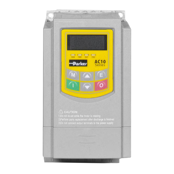
Product Overview Product Overview Chapter 2 The external structure of AC10 series inverter has a plastic housing, up to Frame 5. Illustrated is the AC10G-12-0050-XX Metal housing (frame sizes 6-11) uses advanced exterior plastic-spraying and powder-coating process on the surface with colour and detachable one-side door hinge structure adopted for the front cover, convenient for wiring and maintenance. -
Page 15: Control Features
Product Overview 2.2 Control Features Table 2-1 Technical Specification for AC10 series Inverters 3-phase 380-480V (+10%, -15%) Rated Voltage Range 1-phase 220-240V (±15%) Input 3-phase 220-240V (±15%) Rated Frequency 50/60Hz Rated Voltage Range 3-phase 0-INPUT (V) Output 0.50~590.0Hz Frequency Range 800~10000Hz;... -
Page 16: Chapter 3 Installation
Installation Installation Chapter 3 IMPORTANT Read Chapter 14 “Compliance” before installing this unit. 3.1 Equipment Precautions Check for signs of transit damage. Check the product code on the rating label conforms to your requirements. Installation and application environment should be free of rain, drips, steam, dust and oily dirt;... -
Page 17: Minimum Air Clearance
Installation 3.2 Minimum Air Clearance See Chapter 7 Installation and Connection for clearance information. Inverter Figure 3-1 Capacitors are prohibited to be used Derating must be considered when the drive is installed at high altitude (greater than 1000m). This is because the cooling effect of drive is deteriorated due to the thin air, as shown in Figure 3-2 that indicates the relationship between the elevation and rated current of the drive. -
Page 18: Inverters Installed In A Control Cabinet
Installation 3.3 Inverters Installed in a Control Cabinet AC10 Inverter... -
Page 19: Chapter 4 Maintenance
• The model and serial number - see the unit’s rating label • Details of the fault Contact your nearest Parker SSD Drives Service Center to arrange return of the item. You will be given a Returned Material Authorization. Use this as a reference on all paperwork you return with the faulty item. -
Page 20: Chapter 5 The Keypad
The Keypad The Keypad Chapter 5 5.1 The Display The panel covers three sections: data display section, status indicating section and keypad operating section, as shown in Figure 5-1. LED display shows running frequency, flashing target frequency, function code, parameter value or fault code. “DIGIT”... -
Page 21: Panel Mounting Dimensions
The Keypad 5.2.1 Panel Mounting Dimensions Mounting panel Keypad frame Frame back cover Keypad panel size Opening size 5.2.1 Port of control panel Pins 8 core None Grounding Grounding Signal Signal Signal Signal The default length of remote cable is 1m. On the occasion of heavy interference or if remote control cable is longer than 3m, please add Ferrite core on the cable. -
Page 22: The Menu Structure
The Menu The Menu Structure Chapter 6 All keys on the panel are available for user. Refer to Table 6-1 for their functions. Table 6-1 Uses of Keys Keys Names Remarks Menu To call function code and switch over display mode. Enter To call and save data. -
Page 23: Function Codes Switchover In/Between Code-Groups
The Menu 6.1.1 Function Codes Switchover in/between Code-Groups It has more than 300 parameters (function codes) available to the user, divided into sections as indicated in Table 6-3. Table 6-3 Function Code Partition Function Group Function Group Group Name Group Name Code Range Code Range Timing control... -
Page 24: Panel Display
The Menu 6.1.2 Panel Display Table 6-4 Items and Remarks Displayed on the Panel Items Remarks AErr Analog Input has open connection Indicates Communication error Err2 Tuning parameters are set wrong Err3 Instantaneous Over Current Err4 Current Sampling Fault Err5 PID parameters are set wrong Err6 Watchdog Fault... -
Page 25: Installation & Connection
Installation & Connection Installation & Connection Chapter 7 7.1 Installation Inverter should be installed vertically, as shown in Figure 7-1. Sufficient ventilation space should be ensured in its surrounding. Clearance dimensions (recommended) are available from Table 7-1 Clearance Dimensions for installing of the inverter. - Page 26 Installation & Connection Metal Cover Layout Frames 6 - 11 AC10 Inverter...
-
Page 27: Connection
Installation & Connection 7.2 Connection Connect R/L1, S/L2 and T/L3 terminals (L1/R and L2/S terminals for single-phase) with power supply, to grounding, and U, V and W terminals to motor. Motor shall have to be grounded. Otherwise connected motor causes interference. Model Sketch P B U V W... -
Page 28: Power Terminals
Installation & Connection Model Sketch Frame 6 – Frame 11 U V W /R L /S L 3-phase 400V 30kW and above Frame 6 only: 3-phase input 3-phase 230V 15kW 3-phase output Braking 380V~480V Resistor 7.2.1 Power Terminals Terminal Terminals Terminal Function Description Marking R/L1,... -
Page 29: Measurement Of Main Circuit Voltages, Currents And Powers
Installation & Connection 7.3 Measurement of Main Circuit Voltages, Currents and Powers Since the voltages and currents on the inverter power supply and output sides include harmonics, measurement data depends on the instruments used and circuits measured. When instruments for commercial frequency are used for measurement, measure the following circuits with the recommended instruments. - Page 30 Installation & Connection Table 7-2 Measuring Remarks (Reference Item Measuring Point Instrument Measurement Value) Power supply Moving-iron Across R-S, S-T, T-R 400V±15%,230V±15% voltage V1 type AC voltmeter Power supply R, S, and T line Moving-iron side current I1 currents type AC voltmeter At R, S and T, and Electrodynamic type P1=W11+W12+W13 (3-...
-
Page 31: Functions Of Control Terminals
Installation & Connection 7.4 Functions of Control Terminals To operate the inverter the user must operate the control terminals correctly and flexibly. The following is a description of the user terminals and any relevant parameters. Table 7-3 Functions of Control Terminals Terminal Type Description... -
Page 32: Wiring For Digital Input Terminals
Installation & Connection 7.5 Wiring for Digital Input Terminals: Generally, shielded cable is recommended and wiring distance should be as short as possible. When the analogue reference signal is used, it is necessary to take measures to prevent power supply interference (noise). Digital input terminals are only connected for NPN mode (source) or for PNP mode (sink). -
Page 33: Wiring For Positive Sink Electrode (Pnp Mode) -- Switch J7 Set For Pnp
Installation & Connection 7.5.3 Wiring for positive Sink electrode (PNP mode) -- Switch J7 set for PNP. Inverter control board 7.5.4 Wiring for active drain electrode (PNP mode) (Common Collector Mode) Inverter control board External controller The most prevalent wiring mode for I/O depends on where the system is located. In many parts of the world “sink or pull-down”... -
Page 34: Connection Overview
7-10 Installation & Connection 7.6 Connection Overview Refer to following figure for the overall connection for AC10 series inverters. Various wiring modes are available for the terminals whereas not every terminal needs to be connected in each mode when applied. Note: 1. -
Page 35: Terminal Tightening Torques
7-11 Installation & Connection 30kW – 180kW Basic Wiring Diagram for Three-phase AC drives (NPN type) 7.6.1 Terminal Tightening Torques Power PCB Control PCB Power Supply, Frame Size Cover Fan Cover Terminal Terminal Motor Terminal Frame 1 1.13Nm 0.6Nm 0.6Nm 1.13Nm 1.3Nm 1.3Nm... -
Page 36: Basic Methods Of Suppressing The Noise
7-12 Installation & Connection 7.7 Basic Methods of Suppressing the Noise The noise generated by the drive may disturb the equipment nearby. The degree of disturbance is dependent on the drive system, immunity of the equipment, wiring, installation clearance and earthing methods. 7.7.1 Noise propagation paths and suppressing methods ... -
Page 37: Basic Methods Of Suppressing The Noise
7-13 Installation & Connection 7.7.2 Basic methods of suppressing the noise Noise Actions to Reduce the Noise Emission Paths When the external equipment forms a loop with the drive, the equipment may suffer nuisance tripping due to the drive’s ground leakage current. The problem can be solved if the equipment is not grounded. -
Page 38: Field Wire Connections
7-14 Installation & Connection 7.7.3 Field Wire Connections Control cables, input power cables and motor cables should be installed separately and enough clearance should be left among the cables, especially when the cables are laid in parallel and the cable length is over 50 metres. If the signal cables must be laid with the power cables, they should be installed parallel to each other. -
Page 39: Leakage Current
7-15 Installation & Connection 7.7.5 Leakage Current Leakage current may flow through the drive’s input and output capacitors and the motor. The leakage current value is dependent on the distributed capacitance and carrier wave frequency. The leakage current includes ground leakage current and the leakage current between lines. Ground Leakage Current The ground leakage current can not only flow into the drive system, but also other equipment via grounding cables. -
Page 40: Application Of Power Line Filter
7-16 Installation & Connection Note: The motor cable should be screened and earthed at the drive side, if possible, the motor and drive should be grounded separately; Motor cable and control cable should be shielded. The shield must be earthed and avoid entangling at cable end to improve high frequency noise immunity. -
Page 41: Operation And Simple Running
Operation and Simple Running Operation and Simple Running Chapter 8 This chapter defines and explains the terms and names describing the control, running and status of the inverter. Please read it carefully as it will ensure correct operation. 8.1 Basic Conception Control Mode AC10 inverter has the following control modes: sensorless vector control (F106=0), V/HZ control (F106=2) and vector control 1 (F106=3). -
Page 42: Keypad Panel And Operation Method
Operation and Simple Running Fault alarm status The status under which the inverter has a fault and the fault code is displayed. Fault codes mainly include: OC, OE, OL1, OL2, OH, LU, PF1 and PF0 representing “over current”, “over voltage”, “inverter overload”, “motor overload”, “overheat”, “input under-voltage”, “input phase loss”, and “output phase loss”... -
Page 43: Switching Of The Parameters Displayed Under Running Status
Operation and Simple Running description of function code F132 for changing the displayed parameters. 8.2.6 Switching of the parameters displayed under running status Under running status, by default five parameters of running status can be switched over repeatedly and displayed with the keys “M”. These parameters are displayed: output RPM, output current, output voltage, DC BUS voltage. -
Page 44: Operation Process Of Simple Running
Operation and Simple Running Operation process of simple running Table 8-1 Brief Introduction to Inverter Operation Process Process Operation Reference Install the inverter in a location meeting the technical specifications and Installation and operation requirements of the product. Ensure the inverter can operate in the Chapters I, environment anticipated environmental conditions, and the installation allows adequate... -
Page 45: Illustration Of Basic Operation
Operation and Simple Running 8.3 Illustration of Basic Operation Illustration of inverter basic operation: we hereafter show various basic control operation processes by taking a 7.5kW inverter that drives a 7.5kW three-phase asynchronous AC motor as an example. Figure 8-1 Wiring Diagram 1 The parameters indicated on the nameplate of the motor are as follows: 4 poles;... -
Page 46: Setting The Frequency Using The Keypad Panel, And Starting, Forward And Reverse Running, And Stopping Inverter Through Control Terminals
Operation and Simple Running Press the “I” key, to start the inverter; During running, current frequency of the inverter can be changed by pressing ▲ or ▼; Press the “O” key once, the motor will decelerate until it stops running; vii. -
Page 47: Setting The Frequency With Analog Terminal And Controlling The Operation With Control Terminals
Operation and Simple Running Press the “M” key, to enter the programming menu. iii. Study the parameters of the motor: the operation process is the same as that of example 1. (Refer to 8.3.1 for tuning of the motor). Set functional parameters of the inverter: Function code Parameter Values... - Page 48 Operation and Simple Running Press the “M” key, to enter the programming menu. iii. Study the parameters of the motor: the operation process is the same as that of example 1. (Refer to 8.3.1 for tuning of the motor). Set functional parameters of the inverter: Function code Parameter Values...
- Page 49 Operation and Simple Running Table 8-2 The Setting of Coding Switch and Parameters for Analog Inputs F203=2, channel AI2 is selected F203=1, channel AI1 is selected SW1 coding switch S1 toggle switch Coding Coding Analog Input AI2 Switch 1 Switch 2 signal 0~5V voltage 0 ~ 10V voltage...
-
Page 50: Chapter 9 Function Parameters
Function Parameters Function Parameters Chapter 9 9.1 Basic Parameters Setting range: User’s Password Mfr’s value: 8 F100 0~9999 When F107=1 with valid password, the user must enter correct user’s password after power on or fault reset if you intend to change parameters. Otherwise, parameter setting will not be possible, and a prompt “Err1”... - Page 51 Function Parameters Setting range: Mfr’s value: 0 F107 Password Valid or Not 0: invalid; 1: valid Setting range: F108 Setting User’s Password Mfr’s value: 8 0~9999 When F107 is set to 0, the function codes can be changed without inputting the password. When F107 is set to 1, the function codes can be changed only after inputting the user’s password by F100.
- Page 52 Function Parameters F114 First Acceleration Time (s) F115 First Deceleration Time (s) F116 Second Acceleration Time (s) Mfr’s value: F117 Second Deceleration Time (s) Setting range: subject to inverter model 0.1~3000 F277 Third Acceleration Time (S) F278 Third Deceleration Time (S) F279 Fourth Acceleration Time (S) F280...
- Page 53 Function Parameters Setting range: Mfr’s value: 0 F122 Reverse Running Forbidden 0: invalid; 1: valid When F122=1, inverter will only run forward no matter the state of terminals and the parameters set by F202. Inverter will not run reverse and forward / reverse switchover is forbidden. If reverse signal is given, inverter will stop.
- Page 54 Function Parameters Setting range: Mfr’s value:0.00Hz F127/F129 Skip Frequency A,B (Hz) 0.00~590.0 Setting range: Mfr’s value: 0.0 F128/F130 Skip Width A,B (Hz) ±2.5 Systematic vibration may occur when the motor is running at a certain frequency. This parameter is set to skip this frequency. The inverter will skip the point automatically when output frequency is equal to the set value of this parameter.
- Page 55 Function Parameters Whatever the value of F131 is set to, corresponding target frequency will flash under stopped status. Target rotary speed is an integral number. If it exceeds 9999, add a decimal point to it. Keypad Displays Current A*.* DC Bus Voltage U*** Output Voltage u***...
- Page 56 Function Parameters When F106 (Control Mode) = 2, the function of F137 is enabled. To compensate low-frequency torque controlled V(%) by V/HZ, output voltage of inverter while low- frequency should be compensated. When F137=0, linear compensation is chosen and it is applied on universal constant-torque load;...
- Page 57 Function Parameters The setting value of V/HZ curve is set by motor load characteristic. , Note: V1<V2<V3<V4<V5<V6 F1<F2<F3<F4<F5<F6.As with low-frequency, if the voltage setting is too high, the motor will overheat or be damaged. Inverter will be stalling or occur over-current protection. Voltage (V) Note: During the process of Flycatching,...
- Page 58 Function Parameters Setting range: F154 Automatic voltage 0: Invalid Mfr’s value: 0 rectification 1: Valid 2:Invalid during deceleration process This function is enabled to keep output voltage constant automatically in the case of fluctuation of input voltage, but the deceleration time will be affected by internal PI adjustor. If deceleration time is forbidden being changed, please select F154=2.
-
Page 59: Operation Control
9-10 Function Parameters 9.2 Operation Control Setting range: 0: Keypad command; Mfr’s 1: Terminal command; F200 2: Keypad+Terminal; Source of start command value: 4 3: MODBUS; 4: Keypad+Terminal+MODBUS Setting range: 0: Keypad command; Mfr’s 1: Terminal command; F201 2: Keypad+Terminal; Source of stop command value: 4 3: MODBUS;... - Page 60 9-11 Function Parameters “down”, or through the “up”, “down” terminals. “Memory of digital given” means after inverter stops, the target frequency is the running frequency before stop. If the user would like to save target frequency in memory when the power is disconnected, please set F220=1, i.e.
- Page 61 9-12 Function Parameters F205 reference for selecting Setting range: Mfr’s value: 0 secondary frequency source Y 0: Relative to max frequency; range 1: Relative to main frequency X Setting range: F206 secondary frequency Y Mfr’s value: 100 range (%) 0~100 When combined speed control is adopted for frequency source, F206 is used to confirm the relative object of the setting range for the secondary frequency.
- Page 62 9-13 Function Parameters Setting range: 0: No function F208 1: Two-line operation mode 1; Mfr’s value: 0 Terminal two-line/three-line 2: Two-line operation mode 2; operation control 3: three-line operation mode 1; 4: three-line operation mode 2; 5: start/stop controlled by direction pulse When selecting two-line type or three-line type), F200, F201 and F202 are invalid.
- Page 63 9-14 Function Parameters 3: Three-line operation mode 1: In this mode, X terminal is enable terminal, the direction is controlled by FWD terminal and REV terminal. Pulse signal is valid. Stopping commands is enabled by opening X terminal. SB3: Stop button SB2: Forward button SB1: Reverse button 4: Three-line operation mode 2:...
- Page 64 9-15 Function Parameters Setting range: F210 Frequency display Mfr’s value: 0.01 accuracy 0.01~2.00 Under keypad speed control or terminal UP/DOWN speed control, frequency display accuracy is set by this function code and the range is from 0.01 to 2.00. For example, when F210=0.5, ▲/▼terminal is pressed at one time, frequency will increase or decrease by 0.5Hz.
- Page 65 9-16 Function Parameters Setting range: Mfr’s value: 0 F216 Auto-start restart attempts 0~5 Setting range: Mfr’s value: F217 Fault reset delay 0.0~10.0 F216 sets the most times of auto-starting in case of repeated faults. If starting times are more than the setting value of this function code, inverter will not reset or start automatically after fault.
-
Page 66: Multifunctional Input And Output Terminals
9-17 Function Parameters Setting range: 0: None 1: Basic speed control F228 Application selection 2: Auto/manual speed control Mfr’s value: 0 3: Preset speed control 4: Terminal speed control 5: PID control ·F228 can be set to Mfr’s value by F160=1. 9.3 Multifunctional Input and Output Terminals 9.3.1 Digital multifunctional output terminals Mfr’s value: 1... - Page 67 9-18 Function Parameters Value Function Instructions After motor overloads, ON signal is output after the half time of protection timed, ON signal stops Motor overload pre-alarm outputting after overload stops or overload protection occurs. During accel/decel process, inverter stops Stalling accelerating/decelerating because inverter is stalling, and ON signal is output.
- Page 68 9-19 Function Parameters Setting range: F303 DO1 output types selection 0: level output Mfr’s value: 0 1 : pulse output When level output is selected, all terminal functions in table 9-2 can be defined by F301. When pulse output is selected, DO1 can be defined as high-speed pulse output terminal. The max pulse frequency is 50KHz.
-
Page 69: Digital Multifunctional Input Terminals
9-20 Function Parameters Mfr’s value: 0.00 F312 At Speed threshold Setting range: 0.00~5.00Hz When F300=15 or F301=15, threshold range is set by F312. For example: when F301=15, target frequency is 20HZ and F312=2, the running frequency reaches 18Hz (20-2), ON signal is output by DO1 until the running frequency reaches target frequency. - Page 70 9-21 Function Parameters Table 9-3 Instructions for digital multifunctional input terminal Value Function Instructions Even if signal is input, inverter will not work. This No function function can be set by undefined terminal to prevent mistake action. When running command is given by terminal or terminals combination and this terminal is valid, inverter will run.
- Page 71 9-22 Function Parameters Value Function Instructions When this input is true, and F207=3, the main frequency source is switched with the sum of the main and the secondary frequency sources. Fire pressure switchover When PID control is valid and this terminal is valid, the setting value of PID switches into fire pressure given (FA58).
- Page 72 9-23 Function Parameters Figure 9-6 PTC Heat Protection When the coding switch is in the end of “NPN”, PTC resistor should be connected between CM and DIx terminal. When the coding switch is in the end of “PNP”, PTC resistor should be connected between DIx and 24V.
- Page 73 9-24 Function Parameters Frequency setting Parameters None None Note: 1. K4 is multi-stage speed terminal 4, K3 is multi-stage speed terminal 3, K2 is multi- stage speed terminal 2, K1 is multi-stage speed terminal 1. And 0 stands for OFF, 1 stands for 0=False, 1=True Mfr’s value: 0 F324 Free stop terminal...
-
Page 74: Analog Input Monitoring
9-25 Function Parameters 9.3.3 Analog input monitoring F331Monitoring AI1 Only read F332 Monitoring AI2 Only read The value of analog is displayed by 0~4095. F335 Relay output simulation Setting range: Mfr’s value: 0 0:Output true F336 DO1 output simulation Mfr’s value: 0 1:Output false F337 DO2 output simulation... - Page 75 9-26 Function Parameters For example: when F400=1, F402=8, if analog input voltage is lower than 1V, system judges it as 0. If input voltage is higher than 8V, system judges it as 10V (suppose analog channel selects 0-10V). If Max frequency F111 is set to 50Hz, the output frequency corresponding to 1- 8V is 0-50Hz.
- Page 76 9-27 Function Parameters Mfr’s value: 0.01 F406 Lower limit of AI2 channel input (V) Setting range: 0.00~F408 F407 Corresponding setting for lower limit Mfr’s value: 1.00 Setting range: 0~F409 of AI2 input Mfr’s value: 10.00 F408 Upper limit of AI2 channel input (V) Setting range: F406~10.00 Setting range: F409 Corresponding setting for upper limit...
- Page 77 9-28 Function Parameters 0-5V and the output frequency is 10-120Hz. AO1 output compensation is set by F426. Analog excursion can be compensated by setting F426. Setting range: Mfr’s value: 0 0: 0~20mA; F427 AO2 output range 1: 4~20 mA F428 AO2 lowest corresponding Mfr’s value: 0.05 Setting range: 0.0~F429 frequency (Hz)
-
Page 78: Multi-Stage Speed Control
9-29 Function Parameters F460 AI1channel input mode Setting range: Mfr’s value: 0 0: straight line mode 1: folding line mode F461 AI2 channel input mode Setting range: Mfr’s value: 0 0: straight line mode 1: folding line mode F462 AI1 insertion point A1 voltage value (V) Setting range: F400~F464 Mfr’s value: 2.00 F463 AI1 insertion point A1 setting value Mfr’s value: 1.20... - Page 79 9-30 Function Parameters Setting range: 0: 3-stage speed; Mfr’s value: 1 F500 Stage speed type 1: 15-stage speed; 2: Max 8-stage speed auto circulating In case of multi-stage speed control (F203=4), the user must select a mode by F500. When F500=0, 3-stage speed is selected.
- Page 80 9-31 Function Parameters After circulating Start auto 100 times Stage-1 Stage-2 Stage-3 Keep running at circulating speed Stage-3 speed speed speed running Figure 9-10 Auto-circulating Running The inverter can be stopped by pressing “O” or sending “O” signal through terminal during auto-circulation running.
-
Page 81: Auxiliary Functions
9-32 Function Parameters 9.6 Auxiliary Functions Setting range: 0: Disabled 1: Braking before starting Mfr’s value: 0 F600 DC Braking Function Selection 2: Braking during stopping 3: Braking during starting and stopping Setting range: 0.20~5.00 Mfr’s value: 1.00 F601 Initial Frequency for DC Braking (Hz) F602 DC Braking efficiency before Starting Mfr’s value: 10 Setting range: 0~100... - Page 82 9-33 Function Parameters Setting range: 0: Disabled; 1: Enabled F607 Selection of Stalling Adjusting 2: Reserved Mfr’s value: 0 Function 3: Voltage current control 4: Voltage control 5: Current control Mfr’s value: 160 F608 Stalling Current Adjusting (%) Setting range: 60~200 Mfr’s value: F609 Stalling Voltage Adjusting (%) Setting range: 110~200...
- Page 83 9-34 Function Parameters When DC bus voltage is higher than the setting value of this function, the braking unit starts working. After DC bus voltage is lower than the setting value, braking unit stops working. Dynamic braking duty ratio is set by F612, the range is 0~100%. If the braking duty ratio is higher, the braking effect is better, but the braking resistor will get hotter Setting range: 0: Disabled...
- Page 84 9-35 Function Parameters Setting range: F622 Dynamic braking mode 0: Fixed duty ratio Mfr’s value: 1 1: Auto duty ratio When F622=0, fixed duty ratio is valid. When bus-line voltage reaches energy consumption brake point set by F611, braking module will start dynamic braking according to F612. When F622=1, auto duty ratio is valid.
-
Page 85: Malfunction And Protection
9-36 Function Parameters 9.7 Malfunction and Protection Setting range: Mfr’s value: 0 F700 Selection of terminal free stop mode 0: free stop immediately; 1: delayed free stop F701 Delay time for free stop and programmable Mfr’s value: 0.0 Setting range: 0.0~60.0 terminal action “Selection of free stop mode”... - Page 86 9-37 Function Parameters Time (minutes) 100% Motor overload coefficient 110% 140% 160% 200% Current Figure 9-12 Motor overload coefficient When the output frequency is lower than 10Hz, the heat dissipation effect of common motor will be worse. So when running frequency is lower than 10Hz, the threshold of motor overload value will be reduced.
- Page 87 9-38 Function Parameters Setting range: F708 Trip 1 Type (Newest) 2: Over current (OC) F709 Trip 2 Type 3: Over voltage (OE) 4: Input phase loss (PF1) 5: Inverter overload (OL1) 6: Under voltage (LU) 7: Overheat (OH) 8: Motor overload (OL2) 11: External malfunction (ESP) 12: Current fault before running (Err3)
- Page 88 9-39 Function Parameters Subject to F732 Under-voltage threshold (V) Setting range: 0~450 inverter model “Under-voltage” refers to too low voltage at AC input side. “Input phase loss” refers to phase loss of three-phase power supply, 5.5 kW and below inverters have not got this function. “Output phase loss”...
-
Page 89: Motor Parameters
F800 will be automatically set back to 0. The user may also calculate and input the motor’s mutual inductance value manually according to actual motor data. With regard to calculation formula and method, contact Parker for consultation. - Page 90 9-41 Function Parameters When tuning the motor’s parameter, motor is not running but it is powered on. Do not touch motor during this process. *Note: 1. No matter which tuning method of the motor parameters is adopted, set the information of the motor (F801-F805) correctly according to the nameplate of the motor.
- Page 91 9-42 Function Parameters F803=8.8 F802= 380 F805= 1440 F810= 50 F801=3.7 Press Target TEST is F800=1 frequency is “I”key displayed blinking F812 Pre-exciting time Setting range: 0.000~30.00s 0.30s Setting range: 0.01~20.00 (for 22kW and below Subject to inverter F813 Rotary speed loop KP1 22kW) model 1~100 (for above 22kW)
-
Page 92: Communication Parameter
9-43 Function Parameters adjustment each time should not be too large. In the event of weak loading capacity or slow rising of rotary speed, increase the value of KP first under the precondition of ensuring no oscillation. If it is stable, increase the value of KI properly to speed up response. - Page 93 9-44 Function Parameters FA02 PID feedback signal given source Setting range: Mfr’s value: 1 1: AI1 2: AI2 When FA02=1, PID reference feedback signal is given by external analog AI1. When FA02=2, PID reference feedback signal is given by external analog AI2. FA03 Max limit of PID adjusting (%) FA04~100.0 Mfr’s value:100.0...
- Page 94 9-45 Function Parameters Setting range: FA19 Proportion Gain P Mfr’s value: 0.3 0.00~10.00 Setting range: FA20 Integration time I (s) Mfr’s value: 0.3 0.1~100.0 Setting range: FA21 Differential time D (s) Mfr’s value: 0.0 0.0~10.0 Setting range: FA22 PID sampling period (s) Mfr’s value: 0.1 0.1~10.0 Increasing proportion gain, decreasing integration time and increasing differential time can...
- Page 95 9-46 Function Parameters FA58 Fire pressure given value (%) Setting range: Mfr’s value: 80.0 0.0~100.0 FA58 is also called second pressure, when the fire pressure switchover terminal is valid, pressure target value will switch into second pressure value. Setting range: 0: Disabled FA59 Emergency fire mode Mfr’s value: 0...
-
Page 96: Torque Control Parameters
9-47 Function Parameters 9.11 Torque control parameters 0:Speed control FC00 Speed/torque control selection 1:Torque control Mfr’s value: 0 2:Terminal switchover 0: Speed control. Inverter will run by frequency setting. Output torque will automatically match the torque of load, and output torque is limited by max torque (set by manufacture.) 1: Torque control. - Page 97 9-48 Function Parameters 0: Digital given (FC23) (adjust with keypad) FC22 Forward speed limited channel 1: Analog input AI1 2: Analog input AI2 FC23 Forward speed limited (%) 0~100.0 10.0 0: Digital given (FC25) (adjust with keypad) FC24 Reverse speed limited channel 1: Analog input AI1 2: Analog input AI2 FC25...
-
Page 98: Chapter 10 Troubleshooting
Current alarm signal exists Current Malfunction connected to power board Err3 Before Running before running Contact Parker Flat cable is loosened Check the flat cable Current Zero Err4 Current detector is broken Excursion Malfunction... - Page 99 10-2 Troubleshooting Fault Description Causes Possible Solution Reduce load; *check drive ratio Motor Load too heavy O.L2 Increase motor’s capacity Overload Load is too heavy Decrease the load Motor parameters measurement PMSM tuning fault ...
-
Page 100: Chapter 11 Technical Specifications
Brake Suggested Efficency 380V/ 460V/ Supply Part number Current protection Continuous Peak A Power kW Resistor 230V current ohms 400V 480V 10G-11-0015-XX 10G-11-0025-XX 0.37 10G-11-0035-XX 0.55 1Ph 220V 10G-11-0045-XX 0.75 18.1 10G-12-0050-XX 10.8 24.5 10G-12-0070-XX 25.2 10G-12-0100-XX 10G-31-0015-XX 10G-31-0025-XX 0.37 10G-31-0035-XX 0.55... -
Page 101: Chapter 12 Modbus Communication
12-1 Modbus Communication Modbus Communication Chapter 12 12.1 General Modbus is a serial and asynchronous communication protocol. Modbus protocol is a general language applied to PLC and other controlling units. This protocol has defined an information structure which can be identified and used by a controlling unit regardless of whatever network they are transmitted. -
Page 102: Frame Structure
12-2 Modbus Communication 12.4 Frame structure: ASCII mode Byte Function Start Bit (Low Level) Data Bit Parity Check Bit (None for this bit in case of no checking. Otherwise 1 bit) Stop Bit (1 bit in case of checking, otherwise 2 bits) RTU mode Byte Function... -
Page 103: Protocol Converter
12-3 Modbus Communication 12.5.3 Protocol Converter It is easy to turn a RTU command into an ASCII command followed by the lists: 1. Use the LRC replacing the CRC. 2. Transform each byte in RTU command into a corresponding two byte ASCII. For example: transform 0x03 into 0x30, 0x33 (ASCII code for 0 and ASCII code for 3). -
Page 104: Running Status Parameters
12-4 Modbus Communication 12.6.2 Running Status Parameters Parameters Parameter Description(read only) Address 1000 Output frequency 1001 Output voltage 1002 Output current 1003 Pole numbers/ control mode, high-order byte is pole numbers, low- order byte is control mode. 1004 Bus voltage 1005 Drive ratio/inverter status High-order byte is drive ratio, low-order byte is inverter status... -
Page 105: Control Commands
12-5 Modbus Communication Reading Function Remarks parameter address 100A Read integer power value The integer power value is read by PC. 100B DI terminal status DI1~DI8—bit0~bit7 100C Terminal output status bit0-OUT1 bit2-fault relay 100D 0~4095 read input analog digital value 100E 0~4095 read input analog digital value 1010... -
Page 106: Illegal Response When Reading Parameters
12-6 Modbus Communication 000B: Reverse jogging stop 2001 Lock parameters 0001:Unlock System (remote control locked) 0002:Lock remote control (any remote control commands are not valid before unlocking) 0003: RAM and EEprom are permitted to be written. 0004: Only RAM is permitted to be written, EEprom is prohibited being written. -
Page 107: Function Codes Related To Communication
12-7 Modbus Communication 12.7 Function Codes Related to Communication Mfr’s Function Code Function Definition Setting Rang Value 0: Keypad command; 1: Terminal command; Source of start 2: Keypad+Terminal; F200 command 3: MODBUS; 4: Keypad+Terminal+MODBUS 0: Keypad command; 1: Terminal command; Source of stop 2: Keypad+Terminal;... -
Page 108: Physical Interface
12-8 Modbus Communication 12.8 Physical Interface 12.8.1 Interface instruction The RS485 communication interface is located on the control terminals, marked A+ and B- 12.8.2 Structure of Field Bus PLC/PC Field Bus Inverter Inverter Connecting Diagram of Field Bus RS485 Half-duplex communication mode is adopted for AC10 series inverter. Daisy chain structure is adopted by 485 Bus-line. -
Page 109: Examples
12-9 Modbus Communication 12.9.1 Examples Example1: In RTU mode, change acc time (F114) to 10.0s in NO.01 inverter. Query Register Register Preset Preset Address Function CRC Lo CRC Hi Address Hi Address Lo Data Hi Data Lo Function code F114 Value: 10.0S Normal Response Respon... - Page 110 12-10 Modbus Communication Example 3: No.1 Inverter runs forwardly. Host Query: Write Write Address Function Register Hi Register Lo status status CRC Lo Communication parameters address 2000H Forward running Slave Normal Response: Write Write Address Function Register Hi Register Lo status status CRC Lo...
-
Page 111: Chapter 13 The Default Applications
13-1 The Default Applications The Default Applications Chapter 13 The drive is supplied with 5 Applications, Application 0 to Application 5. Please refer to following: Application 1 is the factory default application, providing for basic speed control. Application 2 supplies speed control using a manual or auto set-point. Application 3 supplies speed control using preset speeds. -
Page 112: Application 1: Basic Speed Control (F228 = 1)
13-2 The Default Applications 13.1 Application 1: Basic Speed Control (F228 = 1) AC10 Inverter... - Page 113 13-3 The Default Applications This Application is ideal for general purpose applications. The set-point is the sum of the two analogue inputs AI1 and AI2, providing Speed Set-point + Speed Secondary capability. B not used A not used Analog output F431=0 , running frequency is output .
-
Page 114: Application 2 : Auto/Manual Control (F228 = 2)
13-4 The Default Applications 13.2 Application 2 : Auto/Manual Control (F228 = 2) AC10 Inverter... - Page 115 13-5 The Default Applications Two Run inputs and two Set-point inputs are provided. The Auto/Manual switch selects which pair of inputs is active. The Application is sometimes referred to as Local/Remote. B not used A not used Analog output F 431=0 , running frequency is output Auto Auto setpointAI 2 input 4-20 mA...
-
Page 116: Application 3: Preset Speeds (F228 = 3)
13-6 The Default Applications 13.3 Application 3: Preset Speeds (F228 = 3) AC10 Inverter... - Page 117 13-7 The Default Applications This is ideal for applications requiring multiple discrete speed levels. The set-point is selected from either the sum of the analogue inputs, or as one of up to eight other pre-defined speed levels. These are selected using DI2, DI3 and DI4, refer to the Truth Table below.
-
Page 118: Application 4 : Raise/Lower Secondary (F228 = 4)
13-8 The Default Applications 13.4 Application 4 : Raise/Lower Secondary (F228 = 4) AC10 Inverter... - Page 119 13-9 The Default Applications This Application mimics the operation of a motorised potentiometer. Digital inputs allow the set-point to be increased and decreased between limits. The Application is sometimes referred to as motorised Potentiometer. B not used A not used Analog output F431=0 , running frequency is output .
-
Page 120: Application 5: Pid (F228 = 5)
13-10 The Default Applications 13.5 Application 5: PID (F228 = 5) AC10 Inverter... - Page 121 13-11 The Default Applications A simple application using a Proportional-Integral-Derivative 3-term controller. The set-point is taken from AI1, with feedback signal from the process on AI2. The difference between these two signals is taken as the PID error. The output of the PID block is then used as the drive set- point.
-
Page 122: Chapter 14 Compliance
December 2006 concerning the Registration, Evaluation, Authorization, and Restriction of Chemicals (REACH) entered into force on June 1, 2007. Parker agrees with the purpose of REACH which is to ensure a high level of protection of human health and the environment. -
Page 123: European Compliance
14.2 European Compliance CE Marking The CE marking is placed upon the product by Parker Hannifin Manufacturing Ltd to facilitate its free movement within the European Economic Area (EEA). The CE marking provides a presumption of conformity to all applicable directives. Harmonized standards are used to demonstrate compliance with the essential requirements laid down in those relevant directives. -
Page 124: Emc Standards Comparison
14-3 Compliance Definitions Category C1 PDS (Power Drive System) of rated voltage less than 1000V, intended for use in the first environment Category C2 PDS (Power Drive System) of rated voltage less than 1000V, which is neither a plug in device nor a movable device and, when used in the first environment, is intended to be installed and commissioned only by a professional. - Page 125 14-4 Compliance Radiated Emissions Profile EN61800-3 - Limits for electromagnetic radiation disturbance in the frequency band 30 MHz to 1000 MHz Category C1 Category C2 Frequency band Electric field strength Electric field strength component component Quasi-peak dB(V/m) Quasi-peak dB(V/m) 30 f 230 230 f 1 000 NOTE: Measurement distance 10 m.
-
Page 126: North American & Canadian Compliance Information
BUSSMANN LLC Class T Fuse.” Or equivalent. Recommended input fuse selection listed below: Frame Size or Model Fuse Model Fuse Current Rating 10G-31-0015-XX 10G-31-0025-XX JJS-15 10G-31-0035-XX 10G-31-0045-XX 10G-32-0050-XX 10G-32-0070-XX JJS-25 10G-32-0100-XX 10G-11-0015-XX 10G-11-0025-XX JJS-15 10G-11-0035-XX 10G-11-0045-XX 10G-12-0050-XX 10G-12-0070-XX JJS-25 10G-12-0010-XX AC10 Inverter... - Page 127 14-6 Compliance Frame Size or Model Fuse Model Fuse Current Rating 10G-41-0006-XX 10G-41-0010-XX JJS-6 10G-41-0015-XX 10G-42-0020-XX 10G-42-0030-XX JJS-15 10G-42-0040-XX 10G-42-0065-XX 10G-43-0080-XX 10G-43-0090-XX JJS-30 10G-43-0120-XX 10G-44-0170-XX JJS-45 10G-44-0230-XX JJS-60 10G-45-0320-XX JJS-80 10G-45-0380-XX JJS-90 10G-45-0440-XX JJS-100 100A 10G-46-0600-XX AJT-125 125A 10G-47-0750-XX AJT-150 150A 10G-47-0900-XX AJT-200...
- Page 128 (AWG) 10G-31-0015-XX Input and 10G-31-0025-XX Output Terminal STR/SOL 10G-31-0035-XX Block 10G-31-0045-XX 10G-32-0050-XX Input and 10G-32-0070-XX Output Terminal STR/SOL Block 10G-32-0100-XX 10G-11-0015-XX Input and 10G-11-0025-XX Output Terminal STR/SOL 10G-11-0035-XX Block 10G-11-0045-XX 10G-12-0050-XX Input and 10G-12-0070-XX Output Terminal STR/SOL Block 10G-12-0010-XX 10G-41-0006-XX...
- Page 129 14-8 Compliance Required Torque Wire Range Wire Type Frame Size Terminal Type (in-lbs) (AWG) Block 10G-48-1500-XX Input and Output Terminal 96.0 Block 10G-49-1800-XX Input and Output Terminal 189.0 250kcmil Block 10G-49-2200-XX Input and 300kcmil or Output Terminal 189.0 STR/SOL 2x1/0 Block 10G-410-2650-XX Input and...
- Page 130 Tightening torque and wire range for field grounding wiring terminals are marked adjacent to the terminal or on the wiring diagram. Frame Size Terminal Type Required Torque (in-lbs) Wire Range (AWG) 10G-31-0015-XX 10G-31-0025-XX 10G-31-0035-XX 10G-31-0045-XX 10G-32-0050-XX 10G-32-0070-XX 10G-32-0100-XX 10G-11-0015-XX 10G-11-0025-XX 10G-11-0035-XX 10G-11-0045-XX 10G-12-0050-XX 10G-12-0070-XX 10G-12-0010-XX 10G-41-0006-XX 10G-41-0010-XX 10G-41-0015-XX 10G-42-0020-XX 10G-42-0030-XX 10G-42-0040-XX...
-
Page 131: Declaration Of Conformity
Product Manual must be implemented. Dr. Martin Payn (Drives Engineering & Global EM Compliance Manager) Parker Hannifin Manufacturing Limited, Automation Group, Electromechanical Drives Business Unit, NEW COURTWICK LANE, LITTLEHAMPTON, WEST SUSSEX BN17 7RZ TELEPHONE: +44 (0) 1903 737000, FAX: +44 (0)1903 737100 Registered Number 4806503 England. - Page 132 15-1 Parameter Reference Parameter Reference Chapter 15 Basic parameters: F100-F160 Function Function Mfr’s Value Setting Range Change Code Definition User’s Password √ F100 0~9999 Subject to ○* Inverter’s Rated Current (A) F102 inverter model Subject to ○* F103 Inverter Power (kW) inverter model F104 Reserved...
- Page 133 15-2 Parameter Reference Function Function Mfr’s Value Setting Range Change Code Definition √ subject to F125 Jogging Acceleration Time 0.1~3000S inverter √ F126 Jogging Deceleration Time 0.1~3000S model √ F127 Skip Frequency A 0.00~590.0Hz 0.00 √ F128 Skip Width A ±2.50Hz 0.00 √...
- Page 134 15-3 Parameter Reference Function Function Mfr’s Value Setting Range Change Code Definition subject to ╳ F138 Linear Compensation 1~20 inverter model 1:1.5 2:1.8 ╳ F139 Square Compensation 3:1.9 4:2.0 ╳ F140 Voltage compensation point frequency (Hz) 0~F142 1.00 ╳ F141 Voltage compensation point 1 (%) 0~100%...
- Page 135 15-4 Parameter Reference Running control mode: F200-F230 Function Mfr’s Value Change Function Definition Setting Range Code 0: Keypad command 1: Terminal command ╳ 2: Keypad+Terminal F200 Source of start command 3:MODBUS 4: Keypad+Terminal+MODBUS 0: Keypad command 1: Terminal command ╳ 2: Keypad+Terminal F201 Source of stop command...
- Page 136 15-5 Parameter Reference Function Mfr’s Value Change Function Definition Setting Range Code 0: No function 1: Two-line operation mode 1 2: Two-line operation mode 2 ╳ F208 Terminal operation mode 3: Three-line operation mode 1 4: Three-line operation mode 2 5: Start/stop controlled by direction pulse 0: stop by deceleration time...
- Page 137 15-6 Parameter Reference Multifunctional Input and Output Terminals: F300-F330 Function Function Mfr’s Value Change Setting Range Code Definition 0: No function 1: Inverter fault √ F300 Relay token output 2: At target frequency 1 3: At target frequency 2 4: Free stop (coast stop) √...
- Page 138 15-7 Parameter Reference Function Function Mfr’s Value Change Setting Range Code Definition 0: No function √ 1: Run F316 DI1 terminal function setting 2: Stop 3: Multi-stage speed 1 4: Multi-stage speed 2 √ F317 DI2 terminal function setting 5: Multi-stage speed 3 6: Multi-stage speed 4 7: Reset √...
- Page 139 15-8 Parameter Reference Function Function Mfr’s Value Change Setting Range Code Definition 0: None 1: DI1 negative logic 2: DI2 negative logic 4: DI3 negative logic √ 8: DI4 negative logic F340 Selection of terminal negative logic 16: DI5 negative logic 32: DI6 negative logic 64: DI7 negative logic 128: DI8 negative logic...
- Page 140 15-9 Parameter Reference Analog Input and Output: F400-F480 Function Function Mfr’s Value Change Setting Range Code Definition √ F400 Lower limit of AI1 channel input 0.00~F402 0.01 Corresponding setting for lower limit of AI1 √ F401 0~F403 1.00 input √ F402 Upper limit of AI1 channel input F400~10.00...
- Page 141 15-10 Parameter Reference Function Function Mfr’s Value Change Setting Range Code Definition 0: Running frequency; √ F431 AO1 analog output signal selecting 1: Output current; 2: Output voltage; 3: Analog AI1; 4: Analog AI2; 6: Output torque; √ F432 AO2 analog output signal selecting 7: Given by PC/PLC;...
- Page 142 15-11 Parameter Reference Multi-stage Speed Control: F500-F580 Function Function Mfr’s Value Change Setting Range Code Definition 0: 3-stage speed; ╳ F500 Stage speed type 1: 15-stage speed; 2: Max 8-stage speed auto circulating Selection of Stage Speed Under Auto- √ F501 2~8 circulation Speed Control...
- Page 143 15-12 Parameter Reference Auxiliary Functions: F600-F670 Function Function Mfr’s Value Change Setting Range Code Definition 0: Disabled 1: Braking before starting × F600 DC Braking Function Selection 2: Braking during stopping 3: Braking during starting and stopping √ F601 Initial Frequency for DC Braking 0.20~50.00 1.00 √...
- Page 144 15-13 Parameter Reference Function Function Mfr’s Value Change Setting Range Code Definition ╳ F627 Current Limiting when Flycatching 50-200 0: Disabled √ F631 VDC Adjustment Selection 1: Enabled Subject to √〇 F632 Target voltage of VDC adjustor (V) 200-800 inverter model F633- Reserved...
- Page 145 15-14 Parameter Reference Function Function Mfr’s Value Change Setting Range Code Definition ╳ F706 Inverter Overloading coefficient% 120~190 Motor Overloading coefficient % ╳ F707 20~100 Setting range: △ F708 Trip 1 Type (Newest) 2: Over current (OC) 3: Over voltage (OE) 4: Input phase loss (PF1) △...
- Page 146 15-15 Parameter Reference Function Function Mfr’s Value Change Setting Range Code Definition Subject to Voltage Threshold of Under-voltage ○ F732 0~450 inverter Protection model 0: Disabled F737 Over-current 1 Protection 1: Enabled F738 Over-current 1 Protection Coefficient 0.50~3.00 2.50 △ F739 Over-current 1 Protection Record F740...
- Page 147 15-16 Parameter Reference Function Function Mfr’s Value Change Setting Range Code Definition Subject to 0.01~655.3mH (22kW and below) ○╳ F809 Mutual Inductance(mH) inverter 0.001~65.53mH (above 22kW) model ○╳ F810 Motor Rated Frequency 1.00~590Hz 50.00 √ F812 Pre-exciting Time 0.30 0.000~30.00S Subject to 0.01~20.00 (22kW and below) ○√...
- Page 148 15-17 Parameter Reference Function Function Mfr’s Value Change Setting Range Code Definition 0: None √ F903 Parity Check 1: Odd 2: Even 0: 1200 1: 2400 2: 4800 √ F904 Baud Rate 3: 9600 4: 19200 5: 38400 6: 57600 √...
- Page 149 15-18 Parameter Reference Function Function Mfr’s Value Setting Range Change Code Definition 0: Disabled √ FA59 Emergency fire mode 1: Emergency fire mode 1 2: Emergency fire mode 2 √ FA60 Running frequency of emergency fire F112~F111 50.0 FA61 Reserved When emergency fire control terminal is 0: Inverter cannot be stopped manually ×...
- Page 150 15-19 Parameter Reference Function Function Mfr’s Value Setting Range Change Code Definition 2: Analog input AI √ FC25 Reverse speed limit (%) 0~100.0 10.0 FC26- Reserved FC27 0: Digital given (FC30) ╳ FC28 Driving torque limit source 1: Analog input AI1 2: Analog input AI2 ╳...
- Page 151 Free phone: 00 800 27 27 5374 (from AT, BE, CH, CZ, DE, EE, ES, FI, FR, IE, IL, IS, IT, LU, MT, NL, NO, PT, SE, SK, UK) © 2012 Parker Hannifin Corporation. All rights reserved. Parker Hannifin Manufacturing Limited Automation Group, SSD Drives Europe,...
Need help?
Do you have a question about the 10G-11-0015 and is the answer not in the manual?
Questions and answers