
Subscribe to Our Youtube Channel
Related Manuals for POSBank ANYSHOP PRIME


Summary of Contents for POSBank ANYSHOP PRIME
- Page 1 ANYSHOP_PRIME-PBUM_E (Rev001;150421) Point-of-sale system ANYSHOP PRIME USER manual...
-
Page 2: Table Of Contents
(12) SWITCHING ON POS ....................................32 (13) SHUTTING DOWN POS ....................................33 (14) SYSTEM DRIVERS ..................................... 34 2. ANYSHOP PRIME MODULE POS SYSTEM REPLACEMENT ......................35 (1) SEPARATING LCD MONITOR MODULE ................................35 (2) SEPARATING HINGE MODULE ..................................38 (3) SEPARATING BACK COVER ..................................41 (4) SEPARATING MOTHERBOARD.................................. -
Page 4: Posbank User's Manual Revision History
POSBANK USER manual Revision History Changes to the ANYSHOP PRIME USER manual are listed below. Rev No. Revision History Date /author ANYSHOP_PRIME-PBUM_E J1900 2015.04.21... -
Page 5: Specification
Specification ANYSHOP PRIME J1900 Intel® Celeron™ J1900 (2.0 GHz) quad-core processor Chipset Intel® Atom™ processor Bay Trail SATA 2 (3Gb/s) 2.5 inch SSD 64GB Storage Support AHCI Memory 2G , DDR3L with 1066 or 1333 MT/s Graphic Integrated Intel GMA HD Resolution 15"... -
Page 6: Specification - Outside Size
(1) Specification – Outside size... -
Page 7: Module Explde View
(2) Specification – Module Explode view... -
Page 8: Body Explode View
(3) Specification – Body Explode View... -
Page 9: Monitor Explode View
(4) Specification – Monitor Explode View... -
Page 10: Hinge Explode View
(5) Specification – Hinge Explode view... -
Page 11: Preface
Preface This User's Guide gives information about main unit/IO port layout, basic setup, component installation, and board layout for point of sale system "ANYSHOP PRIME" Intended Audience The User's Guide is intended for technically qualified personnel. It is not intended for general audiences. -
Page 12: Symbol; Mark
SYMBOL; MARK CE MARK This device complies with the requirements of the EEC directive 2004/108/EC with regard to “Electromagnetic compatibility” and 2006/95/EC “Low Voltage Directive”. This device complies with part 15 of the FCC rules. Operation is subject to the following two conditions: (1) This device may not cause harmful interference. -
Page 13: Copyright
Neither this manual, nor any of the material contained herein, may be reproduced without express written consent of the author. ANYSHOP e2 D25 and POSBANK are trademarks of POSBANK Co., Ltd. in the United States and other countries. * Other names and brands may be claimed as the property of others. -
Page 14: Warranty
Warranty We guarantee our POS terminal product and its parts against defects in materials and workmanship, under proper use, for a standard period of 2 years from the original date of purchase. During this period, we will repair or replace defective and/or faulty products or parts without charge to the customer for parts and labor. -
Page 15: Safety Instructions
Safety Instructions To disconnect the machine from the electrical power supply, turn off the power switch and remove the power cord plug from the wall socket. The wall socket must be easily accessible and in close proximity to the machine. Read these instructions carefully. -
Page 16: Notice
Notice Always ensure that the correct power voltage is used as a precaution against fire and electrical shock. 2. Avoid exposing product to direct sunlight. Do not use product in areas of high humidity. Doing so may cause low reliability and/or operational malfunction. Be careful of static electricity on PCB of system with anti-static appliances. -
Page 17: Liability Limitation
This product is qualified by FCC, CE and KC compliances, and is thus governed by these qualifications’ safety regulations. However, the product can affect and be affected by other high frequencies generated around it. As such, POSBANK does not consider liability for any system error or disorder due to this issue. -
Page 18: Installation Recommendations
Installation Recommendations Avoid installing during thunderstorms. (Possibility of dangerous exposure to electricity.) Install away from damp spaces or water-leaks. Beware of static occurrence during installation. Use only ground connected and quality certified power cords and cables. Keep out of direct sun-light, extremely high or low temperatures, or high humidity areas. Install product away from areas prone to shocks or vibration. -
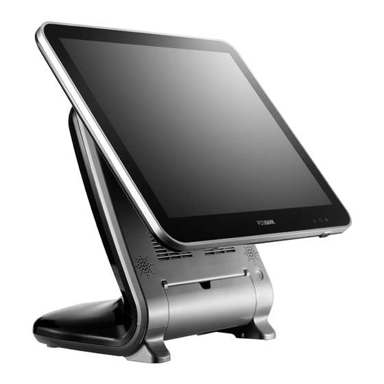
Page 19: Product Overview
2. The POS terminal main unit, power cable, user manual and driver CD are included in the package. If any items are missing or damaged, please contact your dealer for assistance. » All user manuals and drivers are available for download on our website: www.posbank.com ANYSHOP PRIME Main unit Adapter / Power cord installation guide... - Page 20 Optional Devices: 2 LCD monitor 12.1” Optional Devices: 2 LCD monitor 9.7” Optional Devices: CDP (Customer display)
-
Page 21: Pre-Installation Preparation
Remove protective film from touch-screen to prevent possible operating difficulties. 2. Attach all optional parts before setting up the main POS unit. (3) Product Outline • Each part of product may differ depending on the specific POS model. • Model-specific data sheets are provided on our website at www.posbank.com... -
Page 22: Configuration
(4) Configuration Refer to following diagram to identify the components on this side of the system. Front view LCD & Touch panel display LAN LED Storage(Default: HDD) LED Power LED Magnetic stripe reader(MSR); Option Dallas I-button reader; Option Smart card reader(SCR); Option Dual speaker Power switch... - Page 23 Side view I/O port cover USB port (option) Customer display; Option Storage (Default: HDD)
-
Page 24: I/O Port: Details
(5) I/O port : Details * I/O ports may differ according to product model or options. I/O view Raise the main display unit. Pull the bottom and lift up the I/O port cover. ※ Do not pull cable! Disconnect cap from base of unit. - Page 25 Standard I/O port – J1900...
-
Page 26: Setting Up: Keyboard & Mouse Connection
(6) Setting up: Keyboard & Mouse Connection Connecting the keyboard to the PS/2 port on the bottom panel. or connecting the USB type keyboard and mouse to the USB port on the bottom panel. -
Page 27: Setting Up: Connection Usb Port
(7) Setting up: Connection USB Port USB ports are provided in the POS unit, two at the rear I/O and four at the side, all of which support the standard USB 2.0. Some USB devices (optional devices) are only functional with specific driver software installed. If multiple USB devices are used together, this may result in abnormal functionality. -
Page 28: Setting Up: Connection Via Ethernet Port (Lan)
(8) Setting up: Connection via Ethernet Port (LAN) The Ethernet port located at the rear I/O supports 10/100/1000Mbps using an RJ45 connector cable. When connected properly, the LAN LED light will be switched on. Through a network hub. Refer to the table below for the LAN port LED indications. LINK/ACT LED LINK / ACT LED SPEED LED... -
Page 29: Setting Up: Line-Out, Mic-In, Line-In Connection
(9) Setting up: Audio-out, Mic-in connection • Audio out port (lime): This port connects a headphone or a speaker.In4-channel, 6-channel and 8-channel configuration, the function of this port becomes Front Speaker Out. • Microphone port (pink): This port connects a microphone. -
Page 30: Setting Up: Printer Connection
(10) Setting up: Printer Connection Connect printer cable to either Serial &USB port as required. -
Page 31: Setting Up: Power Cable Connection
(11) Setting up: Power Cable Connection The ‘ANYSHOP PRIME ’ POS system is equipped with a 12V/ 5A power adapter. Connect the cable to the DC-IN port on system IO panel. CAUTION : Do not pull on the adaptor cable! Disconnect cable with pulling the plug cap. -
Page 32: Switching On Pos
(12) Switching On POS 1. Press POWER button on the POS unit. (POWER LED will light up.) The power switch is located right hand side of the main body under the display unit. 2. Confirm that Windows loads correctly. -
Page 33: Shutting Down Pos
(13) Shutting Down POS * For product stability, we recommend closing Windows from the O/S. Please make sure that you have closed all applications before closing Windows. Click ‘Start’ and select ‘Turn off Computer’ 2. Click ‘Shut Down’ to close Windows. (ex: POSReady2009 or Windows XP) -
Page 34: System Drivers
(14) System Drivers Please visit our website: www.posbank.com for the latest driver updates. Supported devices: Cash drawer, CDP (Customer Display Panel), MSR (Magnetic Stripe Reader) and printer. Driver installation ● Installation method : Driver will automatically install by clicking SETUP.EXE in your driver CD. -
Page 35: Anyshop Prime Module Pos System Replacement
2. ANYSHOP PRIME Module POS System Replacement (1) Separating LCD monitor module * Warning: Completely remove power cable when opening main unit or installing optional devices. LCD monitor module Step1. Please lift up the I/O cover Step2. Remove the adapter cable. - Page 36 LCD monitor module Step3. Lift up the LCD monitor. Step4. Turn the 2 hand-screws to “open” direction. Step5. Remove the monitor cable.
- Page 37 LCD monitor module Step6 Lift up the LCD monitor module and detach from the main body. Step7. Separate LCD monitor module. Step8. LCD monitor module is now Replacement.
-
Page 38: Separating Hinge Module
(2) Separating Hinge module * Warning: Completely remove power cable when opening main unit or installing optional devices. HINGE module Step1. Please lift up the I/O cover Step2. Remove the adapter cable. Disconnect cap from base of Unit. - Page 39 HINGE module Step3. Lift up the LCD monitor. Step4. Turn the 2 hand-screws to “open” direction. Step5. Remove the monitor cable.분리합니다.
- Page 40 HINGE module Step6 Lift up the LCD monitor module and detach from the main body. Step7. Separate LCD monitor module. Step8. Remove the 4 screws. Step9. Separate the hinge module.
-
Page 41: Separating
(3) Separating Back cover * Warning: Completely remove power cable when opening main unit or installing optional devices. Back cover Step1. Please lift up the I/O cover Step2. Remove the adapter cable. Disconnect cap from base of Unit. - Page 42 Back cover Step3. Remove the 2 screws on front Step4. Remove the Back cover pushing It outward. Step5. Separate the Back cover.
-
Page 43: Separating Motherboard
(4) Separating Mother board * Warning: Completely remove power cable when opening main unit or installing optional devices. Mother Board Step1. Please lift up the I/O cover Step2. Remove the adapter cable. Disconnect cap from base of Unit. - Page 44 Mother Board Step3. Remove the 2 screws on front Step4. Remove the Back cover pushing It outward.. Caution Step5. Turn hand screw and remove Mother board Bracket. (Pull and lift up) Hook Caution : Look at the frame hook before pull and lift up.
- Page 45 Mother Board Zoom in Step4-1 Step4-2 Hook Caution : Look at the frame hook before pull and lift up. Step6. Remove the cables...
- Page 46 Mother Board Step7. Remove the 8 Hexagon bolts, and remove the 4 screws. Step8. Replace the motherboard.
-
Page 47: Separating Hdd
(5) Separating HDD * Warning: Completely remove power cable when opening main unit or installing optional devices. Step1. Please lift up the I/O cover Step2. Remove the adapter cable. Disconnect cap from base of Unit. - Page 48 Step3. Raise the main LCD monitor Module. Pull the bottom and lift up the I/O port cover. Step 4 Step4. Pull out HDD Tray by pressing the grip.
- Page 49 Step5. Open four Tray hinges carefully in opposite directions as in image. Step6. HDD will be separated smoothly. Step7. Assemble HDD bottom to join Tray bottom. Caution: Power must be disconnected before replacing HDD. Before replace the device, remove static electricity of technician.
-
Page 50: Installation Of Optional Devices - Option
3. Installation of Optional Devices * Warning: Completely remove power cable when opening main unit or installing optional devices. (1) LCD monitor module LCD monitor module Step1. Please lift up the I/O cover Step2. Remove the adapter cable. Disconnect cap from base of Unit. - Page 51 LCD monitor module Step3. Lift up the LCD monitor. Step4. Turn the 2 hand-screws to “open” direction. Step5. Remove the monitor cable 분리합니다.
- Page 52 LCD monitor module Step6 Lift up the LCD monitor module and detach from the main body. Step7. Separate LCD monitor module. Step8. LCD monitor module is now Replacement.
-
Page 53: Cdp Module - Option
(2) CDP module – Option * Warning: Completely remove power cable when opening main unit or installing optional devices. CDP-Option Step1. Please lift up the I/O cover Step2. Remove the adapter cable. Disconnect cap from base of Unit. - Page 54 CDP-Option Step3. Remove the 2 screws on front Step4. Remove the Back cover pushing It outward. Caution Step5. Turn hand screw and remove Hook Mother board Bracket. (Pull and lift up) Caution : Look at the frame hook before pull and lift up..
- Page 55 CDP-Option Zoom in Step4-1 Step4-2 Hook Caution : Look at the frame hook before pull and lift up. Step6. Put holes in the sample place. (Image reference) Step7. Reassemble Mother board CABLE reverse procedure of ‘Step4’.
- Page 56 CDP-Option Step8. Reassemble Mother board reverse procedure of [Step3]. Step9. Assemble the CDP module with the mother board bracket of the body. Step10. Assemble CDP module to back of Mother board bracket by hand screw.
- Page 57 CDP-Option Mother board VGA1 connect Position : Put holes in the sample place. (Image reference/VGA1 connect)
- Page 58 CDP-Option Step11. Reassemble back cover procedure of ‘Step1-4’.
-
Page 59: Nd Display Module -Option
(3) 2 Display module –Option * Warning: Completely remove power cable when opening main unit or installing optional devices. 2nd display(10inch, 12.1 inch monitor) – Option Step1. Please lift up the I/O cover Step2. Remove the adapter cable. Disconnect cap from base of Unit. - Page 60 2nd display(10inch, 12.1 inch monitor) – Option Step3. Lift up the LCD monitor. Step4. Turn the 2 hand-screws to “open” direction. Step5. Remove the.
- Page 61 2nd display(10inch, 12.1 inch monitor) – Option Step6 Lift up the LCD monitor module and detach from the main body. Step7. Separate LCD monitor module.
- Page 62 2nd display(10inch, 12.1 inch monitor) – Option display Step8. Fit lower hinge cap under Hinge to put holes in the sample place. Step9. Assemble the 2nd display with the Hinge. Step10. Fasten 1 screw to fix the hinge. Step11. Assemble the 2nd display with the Hinge of the body.
- Page 63 2nd display(10inch, 12.1 inch monitor) – Option Step12. Remove the I/O Cover. Step13. Fit lower hinge cap under Hinge to put holes in the sample place. ( VGA port)
- Page 64 2nd display(9.7inch, 12.1 inch monitor) – Option Position : Put holes in the sample place. (Image reference/VGA Port))
- Page 65 2nd display(10inch, 12.1 inch monitor) – Option Step14. Carefully equip touch monitor. Step15. Tighten the rear screws in the direction of “LOCK” 2nd display installation complete * The unit is successfully installed if the O/S boots on the 2nd display unit.
- Page 66 2nd display(10inch, 12.1 inch monitor) – Option ※ 2 Display BIOS setting mode Step16. While booting POS device, press [Delete] key and enter into BIOS mode. Select [Chipset -> South Bridge]...
- Page 67 Step17. Change VGA 12V Configuration - Disabled to Enabled. Step18. Press the [F4] key to save and exit.
-
Page 68: Msr Module - Option
(4) MSR Module - Option * Warning: Completely remove power cable when opening main unit or installing optional devices. MSR-OPTION Step1. Please lift up the I/O cover Step2. Remove the adapter cable. Disconnect cap from base of Unit. - Page 69 MSR-OPTION Step3. Assemble 2 screws from side using hand. (as shown above) Step 4. Assemble the MSR...
- Page 70 MSR-Option Step 5. Monitor under put holes in the sample place.
- Page 71 MSR-Option Step6. Access to POSBANK homepage Step7. Click on the button on the toolbar (Position : SUPPORT -> Firmware and Drivers ) Step8. Search the MSR at search engine. Step9. Download the MSR mapper file (file name : [POS Peripherals]MSR Utility _Magnetic Stripe Reader(MSR) Utility) Step10.
- Page 72 Step11. Click NEXT.. Step12. After the installation is complete 'Select Device' to Make sure that the choice is normally a FW update.
-
Page 73: Usb Module - Option
(5) USB Module-Replacement * Warning: Completely remove power cable when opening main unit or installing optional devices. USB-Option Step1. Please lift up the I/O cover Step2. Remove the adapter cable. Disconnect cap from base of Unit. - Page 74 USB-Option Step3. Remove the 2 screws on front Step4. Remove the Back cover pushing It outward.. Caution Step5. Turn hand screw and remove Mother board Bracket. (Pull and lift up) Hook Caution : Look at the frame hook before pull and lift up.
- Page 75 USB - Option Zoom in Step4-1 Step4-2 Hook Caution : Look at the frame hook before pull and lift up. Step6. Put a mother board on the body.
- Page 76 USB - Option Step7. Remove the USB module. Step8. Replace the USB module.
-
Page 77: Speaker Module - Option
(6) Speaker module - Option * Warning: Completely remove power cable when opening main unit or installing optional devices. Speaker-Option Step1. Please lift up the I/O cover. Step2. Remove the adapter cable. Disconnect cap from base of Unit. - Page 78 Speaker-Option Step3. Remove the 2 screws on front Step4. Remove the Back cover pushing It outward. Caution Step5. Turn hand screw and remove Mother board Bracket. (Pull and lift up) Hook Caution : Look at the frame hook before pull and lift up.
- Page 79 Speaker-Option Zoom in Step4-1 Step4-2 Hook Caution : Look at the frame hook before pull and lift up. Step6. Assemble 2 Speakers to inner side of body by screws. Step7. Connect each Mother board Speaker connector to Speaker cable.
- Page 80 Speaker-Option Mother board Position : Connect each Mother board Speaker connector to Speaker cable. Harness Harness No : ANH-50 Assemble Right SPEAKER R INSERT BODY Harness No : NDH-05 Extension Cable...
- Page 81 Speaker-Option Harness No : ANH-50 Assemble Left. SPEAKER L INSERT BODY Step8. Reassemble back cover procedure of ‘Step1-4’.
-
Page 82: Memory - Option
(7) Memory - Option * Warning: Completely remove power cable when opening main unit or installing optional devices. Memory -Option Step1. Please lift up the I/O cover. Step2. Remove the adapter cable. Disconnect cap from base of Unit. - Page 83 Memory -Option Step3. Remove the 2 screws on front Step4. Remove the Back cover pushing It outward. Caution Step5. Turn hand screw and remove Mother board Bracket. (Pull and lift up) Hook Caution : Look at the frame hook before pull and lift up.
- Page 84 Memory -Option Zoom in Step4-1 Step4-2 Hook Caution : Look at the frame hook before pull and lift up. Step6. Place Mother board as in image. Step7. Install the Memory.
- Page 85 Memory - Option Memory installation position...
- Page 86 Memory – Option Assemble the RAM(SODIMM) Step8. from the socket. DDR SODIMM notch...
- Page 87 Memory - Option Step9. Reassemble back cover procedure of ‘Step1-4’.
-
Page 88: Cash Drawer - Option
(8) Cash drawer - Option * Warning: Completely remove power cable when opening main unit or installing optional devices. Cash drawer - Option Step1. Please lift up the I/O cover. Step2. Remove the adapter cable. Disconnect cap from base of Unit. - Page 89 Cash drawer - Option Step3. Remove the 2 screws on front Step4. Remove the Back cover pushing It outward. Caution Step5. Turn hand screw and remove Mother board Bracket. (Pull and lift up) Hook Caution : Look at the frame hook before pull and lift up.
- Page 90 Cash drawer - Option Zoom in Step4-1 Step4-2 Hook Caution : Look at the frame hook before pull and lift up. Blanking Step6. Use cutter or ripper to remove Io bracket blanking.
- Page 91 Cash drawer - Option Step7. Assemble a hexagon bolt and fasten Screw to cash drawer. Same image about step6.
- Page 92 Cash drawer - Option Step8. Assemble cable to Mini PCI Board. Zoom-in Step9. Insert Mini PCI Board and fasten two screws..
- Page 93 Cash drawer - Option Cash drawer No1. : Cash drawer to Mini PCI No2. : Mini PCI to Mother board(COM5) MINI PCIE Mother board(COM5) Mini PCIE Harness No : NDH-212-1 Mini PCIE Cash Drawer Harness No : A2H-211...
- Page 94 Cash drawer - Option Step10. Reassemble back cover procedure of ‘Step1-4’.
-
Page 95: Motherboard
4. Motherboard (1) Motherboard Overview This includes description of the jumpers and connectors on the motherboard. Warring Take note of the following precautions before you install motherboard components or change any motherboard settings. Unplug the power cord from the wall socket before touching any component. Before handling components, use a grounded wrist strap or touch a safely grounded object or a metal object, such as the power supply case, to avoid damaging them due to static electricity. -
Page 96: Motherboard Layout
(2-1) Motherboard Layout This includes description of the jumpers and connectors on the motherboard. Motherboard view... - Page 97 NO Description NO Description USB 9 VGA1 USB 7/8 SATA 1/2 RESET SATA_PWR_CN1 / CN2 SWITCH BATTERY1 COM5 MEMORY MEMORY Front monitor connector SYS FAN PARALLEL LVDS1 LVDS_P2 EDP1 SPEAKER-L/ R SPDIF1...
- Page 98 (2-2) Motherboard Pin Assignment Power (Input) port / Adapter Input – 12V Pin Num Description +12V +12V LAN port (RJ45) Pin Num Description Pin Num Description Transmit + (Reserved) Transmit - Receive - Receive + (Reserved) (Reserved) (Reserved) USB port Pin Num Description VSUB(+5V) +...
- Page 99 Pin Num Description Pin Num Description KEY_PWR GREEN BLUE ID0/RES ID2/RES ID1/SDA Hsync RED_RTN Vsync GREEN_RTN ID3/SCL BLUE_RTN Serial port (COM1, COM2, COM3) Pin Num Description Pin Num Description 0V/5V/12V Keyboard port Pin Num Description Pin Num Description KBDAT KB5V KBCLK...
-
Page 100: Jumpers
(3) Jumpers Clear CMOS (CMOS1) This jumper allows you to clear the Real Time Clock (RTC) RAM in CMOS. You can clear the CMOS memory of date, time, and system setup parameters by erasing the CMOS RTC RAM data. The onboard button cell battery powers the RAM data in CMOS, which includes system setup information such as system passwords. - Page 101 2.COM1, COM2, RI/+5V/+12V Select (JCOMPWR1 / JCOMPWR2) R1 (Default) +12V 3. LVDS Backlight control mode (JLVDS_P1) None PWM PWM Mode Mode (Default)
- Page 102 4. LVDS Backlight power selection(JLVDS_P3) 3.3V (Default) 5. VGA2 power selection(CRT_SEL) (Default)
- Page 103 6. Onboard Touch function Enable/Disable selection(USB_SEL) Disable Enable (Default)
-
Page 104: Troubleshooting
6. Troubleshooting (1) Network Issues Symptom Corrective Procedure ▪ Check if hub or switch is working correctly Cannot access LAN ▪ Check RJ45 cable connection ▪ Check if LAN LEDs are on/off ▪ Reinstall LAN card ▪ Replace motherboard (2) MSR Issues Symptom Corrective Procedure ▪... -
Page 105: Touch-Screen Issues
(5) Touch-screen Issues Symptom Corrective Procedure ▪ Check touch-screen cable connection Touch-screen doesn’t detect ▪ Check motherboard and LCD cable connection touch operations ▪ Check BIOS set-up (6) Power Issues Symptom Corrective Procedure ▪ Check A/C cable connection System switches off abruptly and ▪... -
Page 106: Maintenance
7. Maintenance Safety Warning POSBANK will not be held responsible for repairs conducted via USER providers other than those officially specified by the seller. General Guidelines Always disconnect the unit from the power outlet. 2. Disconnect all cables from the POS main unit before attempting reparation.
Need help?
Do you have a question about the ANYSHOP PRIME and is the answer not in the manual?
Questions and answers