Table of Contents
Advertisement
Quick Links
Advertisement
Table of Contents

Subscribe to Our Youtube Channel
Related Manuals for POSBank IMPREX D5


Summary of Contents for POSBank IMPREX D5
- Page 1 PBUM-015E(Rev002;130321) Point-of-sale system IMPREX D5 User’s manual...
-
Page 2: Table Of Contents
(6) POWER ISSUES ................................................. 67 (7) PS/2 KEYBOARD ISSUES ............................................... 67 (8) BOOTING ISSUES................................................67 5. MAINTENANCE ....................................68 IMPREX D5 MODULE POS SYSTEM REPLACEMENT ................................... 68 (1) MOTHERBOARD REPLACEMENT ..........................................69 (2) DC/DC BOARD REPLACEMENT ..........................................74 (3) MEMORY REPLACEMENT ............................................. 75 (4) HDD REPLACEMENT .............................................. - Page 3 Copyright© POSBANK Co., Ltd. All rights reserved. Specifications and information contained in this manual are furnished for informational use only, and are subject to change at any time without notice. The information contained in this document is subject to change without notice.
-
Page 4: Posbank User's Manual Revision History
POSBANK User’s manual Revision History Changes to the IMPREX D5 User’s manual are listed below. Rev No. Revision History Date /author PBUM-015E(Rev001;130116) 2013.01.16... -
Page 5: Preface
Preface This User's Guide gives information about main unit/IO port layout, basic setup, component installation, and board layout for point of sale system "IMPREX D5" Intended Audience The User's Guide is intended for technically qualified personnel. It is not intended for general audiences. -
Page 6: Symbol; Mark
SYMBOL; MARK CE MARK This device complies with the requirements of the EEC directive 2004/108/EC with regard to “Electromagnetic compatibility” and 2006/95/EC “Low Voltage Directive” . This device complies with part 15 of the FCC rules. Operation is subject to the following two conditions: (1) This device may not cause harmful interference. -
Page 7: Copyright
Neither this manual, nor any of the material contained herein, may be reproduced without express written consent of the author. IMPREX and POSBANK are trademarks of POSBANK Co., Ltd. in the United States and other countries. * Other names and brands may be claimed as the property of others. -
Page 8: Warranty
Warranty We guarantee our POS terminal product and its parts against defects in materials and workmanship, under proper use, for a standard period of 2 years from the original date of purchase. During this period, we will repair or replace defective and/or faulty products or parts without charge to the customer for parts and labor. -
Page 9: Safety Instructions
Safety Instructions To disconnect the machine from the electrical power supply, turn off the power switch and remove the power cord plug from the wall socket. The wall socket must be easily accessible and in close proximity to the machine. Read these instructions carefully. -
Page 10: Notice
Notice Always ensure that the correct power voltage is used as a precaution against fire and electrical shock. Avoid exposing product to direct sunlight. Do not use product in areas of high humidity. Doing so may cause low reliability and/or operational malfunction. Be careful of static electricity on PCB of system with anti-static appliances. -
Page 11: Liability Limitation
We recommend that you inquire about product installation, maintenance and repair service from the official service center and agent office. POSBANK takes no responsibility for malfunctions or system errors occurring after service and/or system check carried out by unofficial service providers. -
Page 12: Installation Recommendations
Installation Recommendations Avoid installing during thunderstorms. (Possibility of dangerous exposure to electricity.) Install away from damp spaces or water-leaks. Beware of static occurrence during installation. Use only ground connected and quality certified power cords and cables. Keep out of direct sun-light, extremely high or low temperatures, or high humidity areas. Install product away from areas prone to shocks or vibration. -
Page 13: Product Overview
1. Product Overview (1) Inside Your Package Please check your package and confirm its contents. The POS terminal main unit, power cable, user manual and driver CD are included in the package. If any items are missing or damaged, please contact your dealer for assistance. »... - Page 14 Optional Devices: CDP (Customer display) Optional Devices: 2nd LCD monitor 12.1” Optional Devices: 2nd LCD monitor 15”...
-
Page 15: Pre-Installation Preparation
(2) Pre-installation Preparation Remove protective film from touch-screen to prevent possible operating difficulties. Attach all optional parts before setting up the main POS unit. (3) Product Outline Each part of product may differ depending on the specific POS model. Model-specific data sheets are provided on our website at www.easyset.org... -
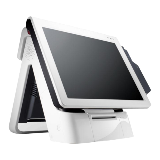
Page 16: Configuration
(4) Configuration Refer to following diagram to identify the components on this side of the system. Front view LAN LED HDD LED Power LED Smart card reader(SCR); Optional Magnetic stripe reader(MSR); Optional Integrated receipt printer LCD & Touch panel display Power switch... - Page 17 Front View (Display Unit Up) LCD & Touch panel display Integrated receipt printer cover Printer cover open button Paper out LED...
- Page 18 Rear/Underside View dummy cover Rubber foot Parallel port - optional EXT USB Integrated receipt printer reset switch Cash drawer port...
-
Page 19: I/O Port: Details
(5) I/O port: Details * I/O ports may differ according to product model or options. Power & I/O port Power connector PS/2 mouse port PS/2 keyboard port COM1, COM2, COM3 port VGA port USB x 3 Ports LAN port... -
Page 20: Installation Of Optional Devices: Cdp
(6) Installation of Optional Devices: CDP CDP Installation * Warning: Completely remove power cable when opening main unit or installing optional devices. Step 1. Connect CDP cable to main unit. Step 2. Insert CDP into slot on main unit. Step 3. Firmly attach using the 3 screws provided. -
Page 21: Installation Of Optional Devices: 2Nd Display
(7) Installation of Optional Devices: 2nd Display 2nd Display * The assembling method of the 2nd Display is equal for all the products. (10.1,12.1,15 inch) Step 1. Separate Dummy Cover. Step 3. Connect the 2nd display into slot on main unit, after connecting the 2nd display cable. -
Page 22: Setting Up: Keyboard & Mouse Connection
(8) Setting up: Keyboard & Mouse Connection Connecting the keyboard and mouse to the PS/2 port on the bottom panel. or connecting the USB type keyboard and mouse to the USB port on the bottom panel. -
Page 23: Setting Up: Connection Usb Port
(9) Setting up: Connection USB Port USB ports are provided in the POS unit, two at the rear I/O and two at the side, all of which support the standard USB 2.0. Some USB devices (optional devices) are only functional with specific driver software installed. If multiple USB devices are used together, this may result in abnormal functionality. -
Page 24: Setting Up: Connection Via Ethernet Port (Lan)
(10) Setting up: Connection via Ethernet Port (LAN) The Ethernet port located at the rear I/O supports 10/100/1000Mbps using an RJ45 connector cable. When connected properly, the LAN LED light will be switched on. Through a network hub. Refer to the table below for the LAN port LED indications. LINK/ACT LED LINK / ACT LED SPEED LED... -
Page 25: Setting Up: Line-Out, Mic-In, Line-In Connection
(11) Setting up: Line-out, Mic-in, Line-in connection • Line In port (light blue): This port connects a tape, CD, DVD player, Sources. • Line Out port (lime): This port connects a headphone or a speaker.In4-channel, 6-channel and 8- channel configuration, the function of this port becomes Front Speaker Out. •... -
Page 26: Setting Up: Power Cable Connection
(12) Setting up: Power Cable Connection The ‘IMPREX D5’ POS system is equipped with a 12V, 5A power adaptor. Connect the cable to the DC-IN port on system IO panel. CAUTION : Do not pull on the adaptor cable! Disconnect cable with pulling the plug cap. -
Page 27: Switching On Pos
(13) Switching On POS The power switch is located left hand side of the main unit. (POWER LED will light up.) When connected to AC source, the POWER LED will be lighted automatically. The unit's status can be determined by each LED lamp. Confirm that Windows loads correctly. -
Page 28: Shutting Down Pos
(14) Shutting Down POS * For product stability, we recommend closing Windows from the O/S. Please make sure that you have closed all applications before closing Windows. Click ‘Start’ and select ‘Turn off Computer’ Click ‘Shut Down’ to close Windows. (ex: POSReady2009 or Windows XP) -
Page 29: Integrated Printer: Control Panel
(15) Integrated Printer: Control Panel Integrated Printer: Control Panel 0000 1. OPEN (Button): Press to open integrated printer. 2. PAPER FEED (Button): Pressing once discharges a short load of paper. Holding down continuously will discharge paper until the button is released again. 3. -
Page 30: Integrated Printer: Self-Test
(16) Integrated Printer: Self-test Integrated Printer: Self-test Make sure the paper roll is installed properly. While holding down the FEED button, turn on the printer to press reset button. The self-test prints out the current ROM version and printer status. Release the FEED button when self-test is finished. -
Page 31: Integrated Printer: Printer Settings
(17) Integrated Printer: Printer settings The printer properties(baudrate, density etc.) can be changed from the printer's 'Setting mode'. To enter 'Setting mode' : Turn off the printer to press reset button. Ensure that the paper roll is inserted properly and the end of the roll is outside the printer with the cover securely fixed. - Page 32 [Switch 1 - Settings] Function Button count Setting Default Step by Step Set in order 2400 BPS 4800 BPS 9600 BPS Serial 19200 BPS 9600 BPS Baudrate 38400 BPS 57600 BPS 115200 BPS Function Button count Setting Default DTR/DSR Serial DTR/DSR Handshaking Xon/Xoff...
- Page 33 [Switch 2 - language] * To select the desired language, press the FEED button the corresponding number of times. Button Count CODE PAGE LANGUAGE Next code page CP-437 USA, Standard Europe Katakana Japanese CP-850 Multilingual PAGE 1 CP-860 Portuguese CP-863 Canadian- French CP-865 Nordic...
-
Page 34: Integrated Printer: Installing New Paper Roll
(18) Integrated Printer: Installing New Paper Roll Installing New Paper Roll Step 1. Raise the main display unit. Step 2. Press the ‘OPEN’ button to open the printer unit cover. OPEN BUTTON... - Page 35 Installing New Paper Roll Step 3. Insert new paper roll exactly as shown figure (with loose paper towards the bottom of the unit). Step 4. Draw out the end of the paper roll and close the cover. When closing the printer cover, press down in the middle to ensure that the paper makes contact with the roller.
-
Page 36: Integrated Printer: Method For Processing Paper-Jam
(19) Integrated Printer: Method for processing paper-jam Method for processing paper-jam Step 1. When paper is jammed in cutter blades, it stops printing. Step 2. First of all, open the cover pressing "Cover open button", and try to remove the jammed paper. -
Page 37: System Drivers
(20) System Drivers Please visit our website: www.posbank.com for the latest driver updates. Supported devices: Cash drawer, CDP (Customer Display Panel), MSR (Magnetic Swipe Reader) and printer. Driver installation ● Installation method : Driver will automatically install by clicking SETUP.EXE in your driver CD. -
Page 38: Motherboard
2. Motherboard (1) Motherboard Overview This includes description of the jumpers and connectors on the motherboard. Warring Take note of the following precautions before you install motherboard components or change any motherboard settings. Unplug the power cord from the wall socket before touching any component. Before handling components, use a grounded wrist strap or touch a safely grounded object or a metal object, such as the power supply case, to avoid damaging them due to static electricity. -
Page 39: Motherboard Layout
(2) Motherboard Layout This includes description of the jumpers and connectors on the motherboard. Motherboard view... - Page 40 NO Description NO Description SATA_PWR_CN2 SYS_FAN SATA 2 CPU_FAN SATA 1 COMPSEL3 SATA_PWR_CN1 VGA 1 LVDS1 CN29(12V DC) Mini PCIe slot CN30(24V DC) COM 6 COMP1SEL2 COM 5 COMP1SEL1 JCOMPWR2 VP1(Inverter) JCOMPWR3 F-Panel1 JCOMPWR1 GPIO1 COMPSEL5 CMOS1 CN15 COMPSEL4 15-1. JAMP1 COM 4 16-1.
-
Page 41: Jumpers
(3) Jumpers Clear RTC RAM (CLRTC) This jumper allows you to clear the Real Time Clock (RTC) RAM in CMOS. You can clear the CMOS memory of date, time, and system setup parameters by erasing the CMOSRTC RAM data. The onboard button cell battery powers the RAM data in CMOS, which include system setup information such as system passwords. - Page 42 COM1, 2, 3, 4, 6RI, +12V and +5V Power Select(COMP1SELx) This jumper allows you to select COM1 RI, +5V and +12V power. Set COMP1SELx top ins 5-6 +5V power. And set COMP1SELx to pins 1-2 +12V power. Then setCOMP1SELx to pins 3-4 for RI selection. COMP1SELx COMP1SEL1 COMP1SEL2...
- Page 43 COM5RS232, RS422, RS485 Select(JCOMPWRx) This jumper allows you to select COM5 RS232, RS422, RS485. Changing jumpers will beselected different RSxxx protocols. JCOMPWRx RS232 RS422RS485 (Default) JCOMPWR1 JCOMPWR2 JCOMPWR3 JCOMPWR2 JCOMPWR3 JCOMPWR1 This jumper allows you to select COM5 RS232, RS422, RS485. Changing jumpers will beselected different RSxxx protocols.
-
Page 44: Bios Setup Utility
3. BIOS Setup Utility * This chapter tells how to change the system settings through the BIOS Setup menus. Detailed descriptions of the BIOS parameters are also provided. (1) Managing and updating your BIOS 1.1 Creating a bootable floppy disk Do either one of the following to create a bootable floppy disk. -
Page 45: Bios Setup Program
(2) BIOS setup program This motherboard supports a programmable firmware chip that you can update using the provided utility described in section “2.1 Managing and updating your BIOS.” Use the BIOS Setup program when you are installing a motherboard, reconfiguring your system, or prompted to “Run Setup”... - Page 46 2.2 List Box This box appears only in the opening screen. The box displays an initial list of configurable items in the menu you selected. 2.3 Sub-menu Note that a right pointer symbol () appears to the left of certain fields. This pointer indicates that you can display a sub-menu from this field.
-
Page 47: Main Setup
(3) Main Setup 3.1Main Menu Press<Del> to enter AMIBIOSCMOS Setup Utility, the Main Menu will appear on the screen. Use arrow keys to select among the items and press <Enter> to accept orenter the sub-menu. The Main BIOS setup screen has two main frames. The left frame displays all the options that can be configured. Grayed-out options can not be configured ;... - Page 48 the<Arrow>keys. All Advanced BIOS Setup options are described in this section. The Advanced BIOS Setup screen is shown below. The submenus are described on the following pages.
- Page 49 3.3CPU Configuration •Max CPUID Value Limit This item allows you to limit CPUID maximum value. •Execute-Disable Bit Capability This item allows you to enable or disable the No-Execution page protection technology. •Hyper Threading Technology This item allows you to enable or disable Intel Hyper Threading technology. •Intel®...
- Page 50 3.4IDE configuration •ATA / IDE Configuration This can be configured as Disabled, Compatible or Enhanced. •Configure SATA as This can be configured as IDE or AHCI. •SATAI/SATA2 While entering setup,the BIOS automatically detects the presence of SATA devices. This displays the status of SATA device auto-detection. •IDE Detect Time Out (Sec) This item allows you to select the time out value for detecting ATA/ ATAPI device(s).
- Page 51 •On board Serial port1 [3F8/IRQ4] This item allows user to adjust serial port1 address and IRQ. •On board Serial port2 [2F8/IRQ3] This item allows user to adjust serial port2 address and IRQ. •On board Serial port3 [C80/IRQII] This item allows user to adjust serial port3 address and IRQ. •On board Serial port4 [C88/IRQI0] This item allows user to adjust serial port4 address and IRQ.
- Page 52 3.5Hardware Health Configuration •CPU warning temperature Use this to set the CPU warning temperature threshold. When the system CPU reaches the warning temperature ,the buzzer will beep.
- Page 53 3.6General ACPI Configuration •Suspend mode Select the ACPI state used for system suspend. •Report Video on S3 Resume This item allows you to invoke VABIOSPOST on S3 / STR resume.
- Page 54 3.7Advanced ACPI Configuration •ACPI Version Features This item allows you to enable RSDP pointers to 64-bit fixed system description tables. •ACPIAPIC support Include ACPI table pointer to RSDT pointer list. •AMI OEMB table Include OEMB table pointer to R(x)SDT pointer lists. •Head less mode Enable/ Disable Head less operation mode through ACPI.
- Page 55 3.8APM Configuration •Power Management/ APM Enable or disable APM power management function. •Restore on AC Power Loss This option allows user to set system action when AC power restores after AC Power loss. Available options include Power Off, Power On, Last Status. •Resume On Ring Disable / Enable RI wake event.
- Page 56 3.9USB Configuration •Legacy USB Support Enables support for legacy USB. Auto option disables legacy support If no USB Devices are connected. •USB2.0 Controller Mode This item allows you to select Hi-Speed (48OMbps) or Full Speed(l2Mpbs). •BIOS EHCI Hand-Off This is a workaround for Oss without EHCI hand-off support. The EHCI owner-ship change should be claimed by EHCI driver.
- Page 57 3.10Advanced PCI/ PnP Settings Select the PCI / PnP tab from the AIMB-2l2 setup screen to enter the Plug andPlay BIOS Setup screen. You can display a Plug and Play BIOS Setup option by highlighting it using the <Arrow> keys. All Plug and Play BIOS Setup options are described in this section.
- Page 58 •Clear NVRAM Set this value to force the BIOS to clear the Non-Volatile Random Access Memory (NVRAM). The Optimal and Fail-Safe default setting is No. •Plug& Play O/S When set to No, BIOS configures all the devices in the system. When set to Yes and if you install a Plug and Play operating system, the operating system configures the Plug and Play devices not required for bootup.
- Page 59 3.11Boot settings Configuration •Quick Boot This item allows BIOS to skip certain tests while booting. This will decrease the time needed to boot the system. •Quiet Boot If this option is set to Disabled,the BIOS displays normal POST messages. If Enabled, an OEM Logo is shown instead of POST messages. •Boot up Num-Lock Select the Power-on state for Numlock.
- Page 60 3.12 Security Setup Select Security Setup from the PCM-9562 Setup main BIOS setup menu. All Security Setup options, such as pass word protect ion and virus protection are described in this section. To access the sub menu for the following items, select the item and press <Enter>...
- Page 61 3.13Advanced Chipset Settings •North Bridge Configuration •South Bridge Configuration...
- Page 62 3.14 North Bridge Chipset Configuration •DRAM Frequency This item allows you to manually change DRAM frequency. •Configure DRAM Timing by SPD This item allows you to enable or disable detect by DRAM SPD. •Initiate Graphic Adapter This item allows you to select which graphics controller to use as the primary boot device. •Internal Graphics Mode Select Select the amount of system memory used by the Internal graphics device.
- Page 63 3.15 Video Function Configuration •DVMT Mode Select Displays the active system memory mode. •DVMT / FIXED Memory Specifies the amount of DVMT/ FIXED system memory to allocate for video memory. •Boot Display Device Select boot display device at post stage. •Flat Panel Type This item allows you to select which panel resolution you want.
- Page 64 3.16 South Bridge Chipset Configuration •USB Functions Select : Disabled, 2 USB Ports, 4USB Ports, 6USB Ports or 8USB Ports. •USB 2.0 Controller Enables or disables the USB2.O controller. •LAN controller Enables or disables the GbE controller. •SLP_S4 # Min. Assertion Width This item allows you to set a delay of a set number of seconds.
- Page 65 3.17 Exit Option •Save Changes and Exit When you have completed system configuration, select this option to you’re your changes, exit BIOS setup and reboot the computer so the new system configuration parameters can take effect. Select Save Changes and Exit from the Exit menu and press <Enter>. The following message appears: Save Configuration Changes and Exit Now? [Ok] / [Cancel]...
-
Page 66: Troubleshooting
4. Troubleshooting (1) Network Issues Symptom Corrective Procedure ▪ Check if hub or switch is working correctly Cannot access LAN ▪ Check RJ45 cable connection ▪ Check if LAN LEDs are on/off ▪ Reinstall LAN card ▪ Replace motherboard (2) MSR Issues Symptom Corrective Procedure ▪... -
Page 67: Touch-Screen Issues
(5) Touch-screen Issues Symptom Corrective Procedure ▪ Check touch-screen cable connection Touch-screen doesn’t detect touch operations ▪ Check motherboard and LCD cable connection ▪ Check BIOS set-up (6) Power Issues Symptom Corrective Procedure ▪ Check A/C cable connection System switches off abruptly and system does not load ▪... -
Page 68: Maintenance
5. Maintenance Safety Warning POSBANK will not be held responsible for repairs conducted via service providers other than those officially specified by the seller. General Guidelines Always disconnect the unit from the power outlet. Disconnect all cables from the POS main unit before attempting reparation. -
Page 69: Motherboard Replacement
(1) Motherboard Replacement Motherboard Replacement Step 1. Pull the bottom and lift up the interface panel. Interface panel is now removed. - Page 70 Motherboard Replacement Step 2. After removing the interface panel, remove the 2 screws from underneath (as shown) Step 3. Pull the second cover off main unit.
- Page 71 Motherboard Replacement Step 4. Remove the 4 screws from either side of the panel underneath. Step 5. Detach from fixtures at either side of panel.
- Page 72 Motherboard Replacement Step 6. Remove motherboard mounting panel (as shown). Motherboard mounting panel is now removed. Step 7. Remove Replace motherboard mounting panel and reassemble unit using the reverse procedure of steps 1-6 above.
- Page 73 Motherboard Replacement Step 7. Remove the 8 Six-angle screws as shown in the picture. These screws can be removed by turning counterclockwise with a designated spanner. Motherboard Step 8. Separate the Motherboard after removing 4 screws. Motherboard is now removed. Step 9.
-
Page 74: Dc/Dc Board Replacement
(2) DC/DC Board Replacement DC/DC Board Replacement Step 1. Separate the Motherboard mounting panel. (Please refer to P.71~73 ) Step 2. Separate the DC/DC Board after removing 3 screws. DC/DC Board... -
Page 75: Memory Replacement
(3) Memory Replacement Memory Replacement Memory Memory Configurations You may install 256 MB, 512 MB, 1GB, 2 GB and 4G unbuffered ECC or non-ECC DDR SO-DIMMs into the SO-DIMM sockets using the memory configurations in this section. - Page 76 Memory Replacement Step 1. Remove motherboard mounting panel (Please refer to P.70~73 ) Step 2. locate the memory(SO-DIMM) socket. (see Figure)
- Page 77 Memory Replacement Step 3. Gently spread the retaining clips at each end of the memory socket. The memory(SO-DIMM) pops out of the socket. Step 4. Remove the memory(SO-DIMM) from the socket.
- Page 78 Memory Replacement Step 5. To replace new memory; Position the new memory above the socket. Step 6. Align the small notch at the bottom edge of the memory with the keys in the socket. Step 7. When the memory is inserted, push down on the top edge of the memory until the retaining clips snap into place.
-
Page 79: Hdd Replacement
(4) HDD Replacement HDD Replacement Step 1. Raise the main display unit. Step 2. Remove HDD cover. Step 3. Remove the 4 screws beneath (as shown figure). - Page 80 HDD Replacement Step 4. Remove the 4 screws from side of HDD and disconnect cable. HDD is now removed. Step 5. Replace HDD and reassemble unit using the reverse procedure of steps 1-4 above.
-
Page 81: Msr Replacement
(5) MSR Replacement MSR Replacement Step 1. Remove 2 screws from side of main unit (as shown figure). Step 2. Detach cable from MSR unit. Step 3. Replace MSR and reassemble unit using the reverse procedure of steps 1-2 above. MSR Replacement. - Page 82 (6) Display Unit Replacement Display Unit Replacement Remove motherboard before replacing monitor. Step 1. Raise the main display unit as far up as possible. Step 2. Remove the 3 screws from underneath (as shown figure)
- Page 83 Display Unit Replacement Step 3. Remove hinge cover. Step 4. Remove the 8 screws from beneath the cover (as shown figure).
- Page 84 Display Unit Replacement Step 5. Disconnect cable connecting monitor to main unit. Step 6. Replace monitor and reassemble unit using the reverse procedure of steps 1-5 above.
-
Page 85: Display Unit Replacement
(7) Integrated Printer: Printer Roller & Bracket Replacement Printer Roller & Bracket Replacement Step 1. Raise the main display unit. Step 2. Open printer cover. - Page 86 Printer Roller & Bracket Replacement Step 3. Remove the 6 screws (as shown figure) from the underside of the printer cover. Roller and bracket are now removed. Step 4. Replace roller and bracket and reassemble unit using the reverse procedure of steps 1-3 above.
-
Page 87: Integrated Printer: Printer Mechanism & Circuit Board Replacement
(8) Integrated Printer: Printer Mechanism & Circuit Board Replacement Printer Mechanism & Circuit Board Replacement Step 1. Raise the main display unit. Step 2. Lift up the printer cover then remove the 4 screws from either side of the main unit. - Page 88 Printer Mechanism & Circuit Board Replacement Step 3. Remove all 8 screws from the areas shown figure. Step 4. Printer mechanism cover is now removed.
- Page 89 Printer Mechanism & Circuit Board Replacement Step 5. Remove all 4 screws from the areas shown figure. Printer mechanism is now removed. Step 6. Replace printer mechanism and reassemble unit using the reverse procedure of steps 1-5 above.
-
Page 90: Integrated Printer: Printer Pcb Replacement
(9) Integrated Printer: Printer PCB Replacement Printer PCB Replacement Step 1. Raise the main display unit. Step 2. Remove two screws. - Page 91 Printer PCB Replacement Step 3. Separate the front cover from bottom to top. Step 4. After separating, check the printer PCB.
- Page 92 Printer PCB Replacement Step 5. Remove four screws and the cable. Printer PCB is now removed. Step 6. Replace printer PCB and reassemble unit using the reverse procedure of steps 1-5 above.
-
Page 93: Specification
Specification Intel Atom processor D525 (1M Cache, 1.8 GHz, Dual Core for Pineview D) Chipset Intel ICH8M SATA HDD 2.5inch (Default 320GB) (Max 2. Optional), Storage SSD is available by option Memory DDR3-800MHz SODIMM 2GB (MAX. 4GB) Integrated Intel Gen3.5+GFX Render Core 400MHz (Pineview-D) Thermal printer 3"...
Need help?
Do you have a question about the IMPREX D5 and is the answer not in the manual?
Questions and answers