Table of Contents
Advertisement
Advertisement
Table of Contents

Subscribe to Our Youtube Channel
Related Manuals for RCF HDL 50-A


Summary of Contents for RCF HDL 50-A
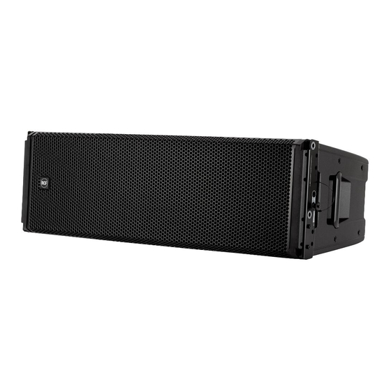
- Page 1 OWNER MANUAL ACTIVE THREE-WAY HDL 50-A LINE ARRAY MODULE...
- Page 2 HDL 50-A is changing the concept of large format arrays, providing primary performances to an extended market of professional users.
-
Page 3: Safety Precautions
Before powering up, make sure that all the connections have been made correctly and the voltage of your mains corresponds to the voltage shown on the rating plate on the unit, if not, please contact your RCF dealer. The metallic parts of the unit are earthed through the power cable. An apparatus with CLASS I construction shall be connected to a mains socket outlet with a protective earthing connection. -
Page 4: General Operating Precautions
(wall, ceiling, structure, etc.), and the components used for attachment (screw anchors, screws, brackets not supplied by RCF etc.), which must guarantee the security of the system / installation over time, also considering, for example, the mechanical vibrations normally generated by transducers. - Page 5 3. THE HDL 50 SYSTEM The HDL 50-A is a true active high power ready to use touring system for large events, indoors and outdoors. Equipped with 2x12” woofers, four symmetrical 6.5” midranges and two 2” drivers, it offers excellent playback quality and high sound pressure levels with a built in 2200W RMS powerful digital amplifier that delivers superior SPL, while reducing energy requirement.
-
Page 6: Rigging The System
Country and local laws and regulations. • Always check that all the parts of the rigging system that are not provided from RCF are: -appropriate for the application... - Page 7 Designer” software it is very easy to understand safety factors and limits for each specific configuration. To better comprehend in which safety range the mechanics are working a simple introduction is needed: HDL 50-A arrays’ mechanics are built with certified UNI EN 10025 Steel. RCF prediction software calculates forces on every single stressed part of the assembly and shows the minimum safety factor for every link.
- Page 8 System very curved PREDICTION SOFTWARE – SHAPE DESIGNER HDL 50-A Shape Designer is a temporary software, useful for the setup of the array, for mechanics and for proper preset suggestions. The optimal setting of a loudspeaker array cannot ignore the basics of acoustics and the awareness that many factors contribute to a sonic result that matches expectations.
-
Page 9: Software Installation
The software was developed with Matlab 2015b and requires Matlab programming libraries. At the very first installation user should refer to the installation package, available from the RCF website, containing the Matlab Runtime (ver. 9) or the installation package that will download the Runtime from the web. Once the libraries are correctly installed, for all the following version of the software the user can directly download the application without the Runtime. - Page 11 After the choice of folders for HDL50-SahpeDesigner software (Figure 2) and Matlab Libraries Runtime the installer takes a couple of minutes for the installation procedure.
- Page 12 DESIGN THE SYSTEM The HDL50 Shape Designer software is divided into two macro sections: the left part of the interface is dedicated to project variables and data (size of audiences to cover, height, number of modules, etc.), the right part shows the processing results.
-
Page 13: Recommended Workflow
NOTE: the 3D model inside the GLL file permits inside AFMG Focus the selection of the “Local” presets. This implies the use of 4 of the 15 presets for the simulation. This limitation will be overcome with the release of the official RCF simulation software. - Page 14 LOW FREQUENCY PRESET USING REAR PANEL ROTARY KNOB The available presets in the rear panel of the loudspeaker, named as “Local” in the software, are only four of the nine available in RDNet. The numbers are proportional, in terms of gain, to the reduction applied to the low frequencies of all the clusters.
- Page 15 HIGH FREQUENCY PRESET USING RDNet From the HDL50 Shape Designer it is possible to export the suggested filters set to RDNet; after the selection of all the cabinets in the cluster, by pressing the Load Presets button in the “group” property tab, the user can choose the “.txt” file generated by HDL50-ShapeDesigner.
- Page 16 RIGGING COMPONENTS Description Accessory p/n FLYBAR HDL 50 A. Suspension bar to fly a maximum of 20 modules 13360334 Front bracket to hook the first module FLY BAR PICK UP TTL 55-A. Hooking bracket and shakle for safety chain 13360127 Mount bracket inclinometer QUICK LOCK PINS KIT 4F.
- Page 17 AC 2X AZIMUT PLATE. It allows the horizontal aim control of the cluster. The system must be hook with 3 motors. 1 frontal and 2 attached to the azimuth plate. 13360336 HDL 50-A 4X KART. Necessary to carry and rigging 4 HDL 50-A...
-
Page 18: Rigging Procedure
Flying frame. Ensure all Locking pins are fully inserted and securely locked before lifting any load. In the first instance use HDL 50-A Shape Designer software to calculate the proper set up of the system and to check the safety factor parameter. - Page 19 PREPARATION OF THE FLYBAR Place the flybar and remove the side pins from the transport position. The front bracket will rotate, so lock it. Fix the front brackets in vertical position locking the pins in position 2. Recheck the Locking pin is securely locked by briefly pulling the Locking pin towards you.
- Page 20 Hook the flybar to the chain and lift the flybar to a suitable height for the first cabinet. PRESET OF SPLAY ANGLES 1. Remove all the rear locking pins of the cabinets turning the rear bracket into the upper module and inserting the pins in the proper position.
- Page 21 Turn down the flybar until it rests on the first speaker. Lift up the rear bracket of the highest cabinet. Insert the quick lock pin in the “suspension” hole “A” of the flybar. Begin to lift the flybar, and when it goes on traction on the first module, insert the locking pin in the hole “B”.
- Page 22 Stop lifting and insert and lock the second Locking pins (Safety pins) to prevent the system from going into compression SUSPENSION shifting the tilt of the module, and consequently of the cluster. ANGLE PIN 5° LOCKING PIN PER SUSPENSION PIN 5° Insert the front locking pins in the proper hole.
- Page 23 Working with one pick up point this is achieved by pushing forward the cluster and simultaneously lowers the height of the system. Now fix and lock the quick lock pin between the first speaker of the cluster on the ground and the last of the hanging cluster. Continue to lift the cluster and the angles of the speakers will automatically switch to the correct position.
-
Page 24: Stacking Procedure
STACKING PROCEDURE A maximum of 4 x TOP cabinets are allowed to be set up as ground stack. The assembly of HDL 50 in stacking uses the same flybar as the hanging process. Proceed as follows: Remove the pick-up front bracket and remove the laser/ inclinometer bracket. - Page 25 On subs 9006 and 9007 series fix the optional accessory “Ac Connecting Plate” cod. 13360231, to M20 female screw on the upper part of the sub. Place the flybar to sub and insert the Ac Connecting Plate between the two cental pipes. Fix the flybar to the Ac Connection Plate using the two quick lock pins.
-
Page 26: Care And Maintenance - Disposal
During transportation ensure the rigging components are not stressed or damaged by mechanical forces. Use suitable transport cases. We recommend the use of the RCF HDL50 touring kart for this purpose. Due to their surface treatment the rigging components are temporarily protected against moisture. However, ensure the components are in a dry state while stored or during transportation and use. -
Page 27: Specifications
SPECIFICATIONS HDL50-A Frequency Response 40 Hz - 20 kHz Max Spl 140 dB Horizontal Coverage Angle 90° Vertical Coverage Angle 10° Compression Driver 2x1.4”, 3.0”v.c. Midrange 4x6.0”, 2.0”v.c. Fullrange Woofer 2x12”, 3.0”v.c. INPUTS Input Connector XLR male, RDNet Output Connector XLR female, RDNet Input Sensitivity + 4 dBu... - Page 28 RCF SpA: Via Raffaello, 13 - 42124 Reggio Emilia - Italy tel. +39 0522 274411 - fax +39 0522 274484 - e-mail: rcfservice@rcf.it...
Need help?
Do you have a question about the HDL 50-A and is the answer not in the manual?
Questions and answers