
Related Manuals for RCF HDL 26-A


Summary of Contents for RCF HDL 26-A
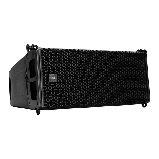
- Page 1 OWNER MANUAL HDL 26-A ACTIVE LINE ARRAY MODULE ACTIVE SUBWOOFER HDL 35-AS ARRAY MODULE...
-
Page 2: Important Note
The manual is to be considered an integral part of the product and must accompany the system when it changes ownership as a reference for correct installation and use as well as for the safety precautions. RCF S.p.A. will not assume any responsibility for the incorrect installation and/or use of the product. - Page 3 8. RCF S.p.A. strongly recommends this product is only installed by professional qualified installers (or specialised firms) who can ensure correct installation and certify it according to the regulations in force. The entire audio system must comply with the current standards and regulations regarding electrical systems.
- Page 4 THE HDL 35-AS The HDL 35-AS is the ideal flyable bass complement for the HDL 26-A array system. It features a baltic birch plywood cabinet housing one 4.0” voice coil, 15” Neodymium woofer to handle frequencies from 40 Hz to 140 Hz with the maximum linearity and lowest distortion.
-
Page 5: Rigging The System
RIGGING THE SYSTEM RCF has developed a complete procedure to set up and hang an HDL 26-A line array system starting from software data, enclosures, rigging, accessories, cables, until the final installation. - Page 6 Shape Designer” software it is very easy to understand safety factors and limits for each specific configuration. To better comprehend in which safety range the mechanics are working a simple introduction is needed: HDL 26-A arrays’ mechanics are built with certified UNI EN 10025 Steel. RCF prediction software calculates forces on every single stressed part of the assembly and shows the minimum safety factor for every link.
- Page 7 System very curved PREDICTION SOFTWARE – SHAPE DESIGNER RCF Easy Shape Designer is a temporary software, useful for the setup of the array, for mechanics and for proper preset suggestions. The optimal setting of a loudspeaker array cannot ignore the basics of acoustics and the awareness that many factors contribute to a sonic result that matches expectations.
-
Page 8: Software Installation
The software was developed with Matlab 2015b and requires Matlab programming libraries. At the very first installation user should refer to the installation package, available from the RCF website, containing the Matlab Runtime (ver. 9) or the installation package that will download the Runtime from the web. Once the libraries are correctly installed, for all the following version of the software the user can directly download the application without the Runtime. - Page 10 After the choice of folders for HDL 26-A Shape Designer software (Figure 2) and Matlab Libraries Runtime the installer takes a couple of minutes for the installation procedure.
-
Page 11: Designing The System
DESIGNING THE SYSTEM The RCF Easy Shape Designer software is divided into two macro sections: the left part of the interface is dedicated to project variables and data (size of audiences to cover, height, number of modules, etc.), the right part shows the processing results. - Page 12 ACTIVE LED. This LED blinks when the speaker is transmitting data over RDNet. RDNET DATA INPUT AND DATA LINK. The RDNET IN/OUT PLUG SECTION features etherCON connectors for the RCF RDNet protocol. This allows the user to completely control the speaker using the RDNet software.
- Page 13 RDNet setup is loaded and bypass any speaker local preset. RDNET IN/OUT PLUG SECTION. The RDNET IN/OUT PLUG SECTION features etherCON connectors for the RCF RDNet protocol. This allows the user to completely control the speaker using the RDNet software.
- Page 14 Accessory p/n Description 13360360 BARRA SOSPENSIONE HDL 6-A - up to 16 HDL 26-A - up to 8 HDL35-AS - up to 4 HDL35-AS + 8 HDL 26-A 13360022 QUICK LOCK PIN 13360372 FLY BAR PICK UP HDL 6-A CONNECTION BRACKET FOR SECURELY LOCKING THE STACKING CLUSTER ON A SUBWOOFER...
- Page 15 ACCESSORIES 13360129 HOIST SPACING CHAIN. It allows enough space for the hang of most 2 motor chain containers and avoids any impact on the vertical balance of the array when it is suspended from a single pick-up point. 13360372 FLY BAR PICK UP HDL 6-A + 2 QUICK LOCK PIN (SPARE PART P/N 13360022) 13360351 AC 2X AZIMUT PLATE.
-
Page 16: Rigging Procedure
In the first instance use the EASY Shape Designer software to calculate the proper set up of the system and to check the safety factor parameter. The HDL 6-A flybar allows the suspension of: - HDL 6-A and HDL12-AS - HDL 26-A and HDL35-AS... - Page 17 1. FLYBAR SETUP The HDL 6-A flybar allows to set the central bar in two different configurations “A” e “B”. Configuration “B” allows a better upper inclination of the cluster. FLYBAR WITH CENTRAL BAR IN “A” POSITION FLYBAR WITH CENTRAL BAR IN “B”...
- Page 18 1.2 PICK UP POINT POSITION UP POINT POSITION POINT ITION PICK UP POINT PICK UP POINT “B” POSITION “A” POSITION PICK UP POINT POSITION PICK UP POINT 2. SYSTEM SUSPENSION PROCEDURE PICK UP POINT PICK UP POINT “B” POSITION PICK UP POINT PICK UP POINT “A”...
- Page 19 1. Insert the frontal quick lock pins “F” 2. Rotate the rear bracket and secure it to the flybar with the rear quick lock pin “S” to the HDL 26-A Link Point hole 2.2 SECURING THE SECOND HDL 26-A SPEAKER TO THE FIRST (AND CONSECUTIVE) 1.
- Page 20 2.3 SECURING THE FLYBAR TO THE FIRST HDL35-AS SPEAKER 1. Insert the frontal quick lock pins “F” 2. Rotate the rear bracket and secure it to the flybar with the rear quick lock pin “S” on the HDL12 Link Point hole. 2.4 SECURING THE SECOND HDL35-AS SPEAKER TO THE FIRST (AND CONSECUTIVE): 1.
- Page 21 2.5 CLUSTER HDL35-AS + HDL 26-A 1. Using the quick lock pin “P”, secure the linking bracket to the HDL 26-A speaker on the “Link point to HDL35-AS” hole, on the rear bracket. 2. Rotate the HDL 26-A rear bracket and block it on the linking bracket between the two metal flaps.
- Page 22 1. Secure the flybar to HDL35-AS 2. Secure the stacking bar“B” (as shown in the picture) to the flybar using the quick lock pin “S” (follow the indication “stacking point”) 1. Secure HDL 26-A to the flybar using the frontal quick lock pins “F1”.
- Page 23 2. Secure the flybar to the safety bracket using the linchpins “X” and block them with the cotter pins “R”. 3. Adjust the feet to stabilize the flybar on the subwoofer then block them with thieir nuts to avoid unscrewing. 4. Assemble the HDL 26-A speaker with the same procedure. WARNING: ALWAYS VERIFY THE SYSTEM SOLIDITY IN EVERY CONFIGURATION...
-
Page 24: Ground Stacking
1. Screw all three plastic feet “P”. 2. Adjust the feet to stabilize the flybar on the subwoofer then block them with thieir nuts to avoid unscrewing. 3. Assemble the HDL 26-A speaker with the same procedure. WARNING: ALWAYS VERIFY THE SYSTEM SOLIDITY IN EVERY CONFIGURATION 3.3 POLE MOUNTING WITH SUSPENSION BAR... - Page 25 3.4 POLE MOUNTING WITH POLE MOUNT 3X HDL 26-A 1. Secure the flybar on the pole by screwing the knob “M” 2. Assemble the speakers HDL 26-A with the same procedure used on stacking on sub HDL35-AS WARNING: ALWAYS VERIFY...
-
Page 26: Care And Maintenance - Disposal
Do not stack more than six HDL 26-A on one Kart. Exercise extreme caution when moving stacks of six cabinets with the Kart to avoid tipping. Do not move stacks in the front-to-back direction of the HDL 26-A’s (the long side); always move stacks sideways to avoid tipping. -
Page 27: Specifications
SPECIFICATIONS HDL 26-A HDL 35-AS Frequency Response 40 Hz - 20 kHz 40 Hz - 140 kHz Max Spl 133 dB 134 dB Horizontal Coverage Angle 100° Vertical Coverage Angle 10° Compression Driver 1.5” neo, 3.0”v.c. Woofer 2 x 6.0” neo, 2.0”v.c. - Page 28 RCF SpA: Via Raffaello, 13 - 42124 Reggio Emilia - Italy tel. +39 0522 274411 - fax +39 0522 274484 - e-mail: rcfservice@rcf.it...
Need help?
Do you have a question about the HDL 26-A and is the answer not in the manual?
Questions and answers