Sign In
Upload
Download
Table of Contents
Contents
Add to my manuals
Delete from my manuals
Share
URL of this page:
HTML Link:
Bookmark this page
Add
Manual will be automatically added to "My Manuals"
Print this page
×
Bookmark added
×
Added to my manuals
Manuals
Brands
Electrolux Manuals
Hob
EHG 9320
Service manual
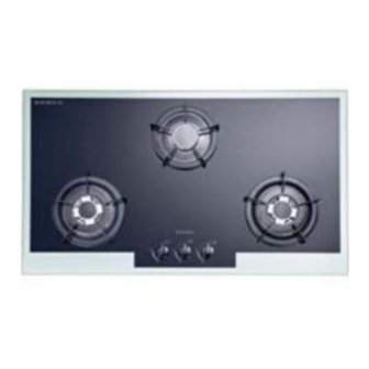
Electrolux EHG 9320 Service Manual
Gas hob on glass and stainless steel
Hide thumbs
1
Table Of Contents
2
3
4
5
6
7
8
9
10
11
12
13
14
15
16
17
18
19
page
of
19
Go
/
19
Contents
Table of Contents
Troubleshooting
Bookmarks
Advertisement
Table of Contents
1
Table of Contents
2
General Notes
3
How Does Gas Burner Operate
4
Components Specification
5
Tools
6
Repair Process
7
Remove the Dirty Oil from Nozzle
8
Wiring Diagram
9
Conversion Details
10
Spare Parts
11
Trouble Shooting
Download this manual
SERVICE MANUAL
Table of
Contents
Previous
Page
Next
Page
1
2
3
4
5
Advertisement
Table of Contents
Need help?
Do you have a question about the EHG 9320 and is the answer not in the manual?
Ask a question
Questions and answers
Related Manuals for Electrolux EHG 9320
Hob Electrolux EHG9832X Instruction Booklet
90cm gas hob with cast iron pan supports (36 pages)
Hob Electrolux EHG 9832 Instruction Booklet
Electrolux gas hob instruction booklet (36 pages)
Hob Electrolux Electric Hobs Brochure & Specs
Induction hobs (4 pages)
Hob Electrolux EHG 97 Instruction Booklet
(13 pages)
Hob Electrolux EHG 97 Instruction Booklet
(12 pages)
Hob Electrolux EHG97X Instruction Booklet
(12 pages)
Hob Electrolux EHG678 Series Instruction Manual
Electrolux built-in hob (8 pages)
Hob Electrolux EHG 75932 Instruction Booklet
Electrolux gas hob (32 pages)
Hob Electrolux EHG 9330 Service Manual
Gas hob on glass and stainless steel (19 pages)
Hob Electrolux EHG 9835 Operating Instructions Manual
(20 pages)
Hob Electrolux EHG9360BS User Manual
Built-in gas hob with steam (13 pages)
Hob Electrolux EHG8321BC Installation & User Manual
(12 pages)
Hob Electrolux EHG8321BC Installation & User Manual
(36 pages)
Hob Electrolux EHG641W Instruction Booklet
60cm gas hob with enamel pan supports (36 pages)
Hob Electrolux EHG6435 User Manual
Electrolux gas hob (60 pages)
Hob Electrolux EHG 770 Instruction Booklet
Electrolux gas hob instruction booklet (17 pages)
This manual is also suitable for:
Egg 9430
Egg 9420
Ehg 9330
Ehg 9340
Table of Contents
Print
Rename the bookmark
Delete bookmark?
Delete from my manuals?
Login
Sign In
OR
Sign in with Facebook
Sign in with Google
Upload manual
Upload from disk
Upload from URL


Need help?
Do you have a question about the EHG 9320 and is the answer not in the manual?
Questions and answers