Lightspeed 955 Access Installation Manual
Access link with cat 885
Hide thumbs
Also See for 955 Access:
- Set up and daily operation instructions (2 pages) ,
- Quick start manual (2 pages) ,
- User manual (53 pages)
Table of Contents
Advertisement
Quick Links
Download this manual
See also:
User Manual
Advertisement
Table of Contents

Related Manuals for Lightspeed 955 Access


Summary of Contents for Lightspeed 955 Access
- Page 1 955 Access Access Link with Cat 885 Access Systems Installation Guide...
-
Page 2: Important Safety Instructions
IMPORTANT SAFETY INSTRUCTIONS Read these instructions. 13. Unplug this apparatus during lightning storms or when Keep these instructions. unused for long periods of Heed all warnings. time. Follow all instructions. 14. Refer all servicing to qualified service personnel. Servicing is Do not use the apparatus required when the apparatus near water. -
Page 3: Table Of Contents
1. Location of the Amplifier Installation Planning 2. Installation of Amplifier Wall Bracket 800WB SECTION 3: Connecting power supply to 955 Access and Cat 885 Connecting Power Connecting Access Link to Cat 885 SECTION 4: TCQ Multimedia Ceiling Speaker Installation Instructions Speaker Location &... -
Page 4: System Components And Unpacking
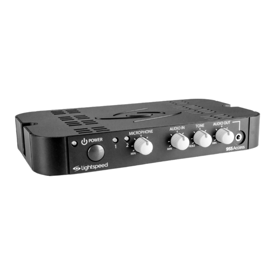
SYSTEM COMPONENTS AND UNPACKING The standard configuration of the Access system will contain: Option #1 MICROPHONE AUDIO IN TONE AUDIO OUT POWER MAX TREBLE BASS 955 Access Receiver/Ampliefier Amplifier Power Supply Option #2 Access Link Audio Hub MICROPHONE AUDIO IN TONE POWER TREBLE... - Page 5 SYSTEM COMPONENTS AND UNPACKING CONT’D Flexmike® Classroom Microphone Flexmike Cradle Charger & Power Supply P5E2.0 Cable (for Option #2)
- Page 6 SYSTEM COMPONENTS AND UNPACKING CONT’D Speakers Systems can be configured with a variety of different speaker types, including the following: TCQ (x 1) DRQ (x 4) 4jCS (x4) WMQ (x 4) (plenum rated) (Available in U.S. and Canada only) (Available in U.S. only)
- Page 7 SYSTEM COMPONENTS AND UNPACKING CONT’D Standard Components (U.S. and Canada) Wireless Audio Base Station (Option #1) Access Link Audio Hub (Option #2) Audio amplifier/mixer (Option #2) 24V-2.5-NA 24V/2.5A power supply for U.S. and Canada P5E2.0 2’ plenum-rated Cat5e cable (Option #2) Flexmike classroom transceiver with battery pack and lanyard NH2.4V AA NiMH rechargeable battery pack for Flexmike, one per Flexmike...
- Page 8 PageFirst sensor clip with wire MSC3535 3.5mm to 3.5mm stereo audio cable Media Connector with power adaptor and MICROPHONE AUDIO IN AUDIO OUT LINK POWER cable Sharemike FCAD (Flexcat Speaker Pods) *For further information on Flexcat for small group instruction, please visit www.lightspeed-tek.com...
-
Page 9: Location Of The Amplifier
It can be set in a cabinet, on a tabletop, or mounted on the wall. The 955 Access may be wall-mounted using the molded screw flanges; appropriate mounting hardware should be purchased locally. The Cat 885 may be located on a wall using the optional 800WB wall-mount bracket. -
Page 10: Installation Of Amplifier Wall Bracket 800Wb
2. INSTALLATION OF AMPLIFIER WALL-MOUNT BRACKET 800WB Wall-mount Set-up Specifications: Dimensions (D x W x H): 11” x 20.7” x 5.5” The optional Lightspeed wall shelf (part Weight: 5.15 lbs #800WB) is specifically designed to support Load Capacity: 25 lbs the Cat 885. - Page 11 2. INSTALLATION OF AMPLIFIER WALL-MOUNT BRACKET 800WB cont’d 1. Use level to determine that the shelf is straight. 2. The back of the shelf (the portion that is flush against the wall) has four mounting holes. Using a pencil, mark the location of the mounting holes onto the wall.
-
Page 12: Connecting Power
SECTION 3: CONNECTING POWER 1. CONNECTING THE POWER SUPPLY TO 955 ACCESS OR CAT 885 1. Ensure the power button is in the off position. 2. Connect the DC end of the power supply to the black power jack labeled DC POWER. - Page 13 2. ACCESS LINK CONNECTION TO CAT 885 When you are connecting Access Link into a Cat 885 amplifier, you can use use Cat 5 cabling to integrate the two components (a 2’ cable is included with the system). This connection will send the audio from Access Link to the Cat 885 as well as provide power for the Access Link (no need for an additional AC power connection).
-
Page 14: Tcq Multimedia Ceiling Speaker Installation Instructions
SECTION 4: SPEAKER LOCATION & INSTALLATION Tools and equipment that may be needed to install the speakers outlined in this manual: • Straight edge • Utility knife or drywall saw • Screwdriver, standard & phillips • Screwdriver, small jewelers type ,1/8” wide tip •... -
Page 15: Installation
TCQ SPEAKER INSTALLATION INTRUCTIONS CONT’D 1. SELECTING SPEAKER Figure 1: Identify the center of the room MOUNTING LOCATIONS 1. One TCQ speaker will distribute sound throughout a classroom of up to 1200 square feet (112 sq m). The location of the speaker is important to ensure even sound distribution. - Page 16 TCQ SPEAKER INSTALLATION INTRUCTIONS CONT’D Throw Away Remaining 2a. SECURING THE TCQ Ceiling Tile Existing Tile Grid New T-Bar SPEAKER (U.S. & CANADA ONLY) To comply with Building Codes, the TCQ Cut with 12” straight MUST be secured to the building structure edge with 2 safety wires.
- Page 17 TCQ SPEAKER INSTALLATION INTRUCTIONS CONT’D 8. Locate the four (4) self-drilling sheet metal screws. 9. Utilizing existing holes on the vertical section of the ceiling rail (center of the hole to the base of the rail must be a minimum of 0.6” - see figure 8), drill two screws on each 2’...
- Page 18 Remove the spacer brackets from each of the four sides of the TCQ. Replace the two screws into the woofer end of the speaker cabinet to ensure proper audio quality Note: If your ceiling grid is any other dimension than mentioned above, contact your local Lightspeed representative. INSTALLING SAFETY WIRE: 1. Locate the 6m length of safety Figure 13: Looping the Safety Wire wire.
- Page 19 TCQ SPEAKER INSTALLATION (OUTSIDE U.S. & CANADA ONLY) cont’d anchor or eye screw Loop the other end of the safety wire through one of the tabs on the TCQ (located in opposite corners). Pull the wire through until it is taut and twist it around itself at least five times to secure the TCQ and cut off any excess wire as needed.
-
Page 20: Drq Ceiling Speaker Installation Instructions
DRQ CEILING SPEAKER INSTALLATION INSTRUCTIONS Tools and Equipment Speaker Components • Small flathead screwdriver • (4) DRQ speakers • Philips screwdriver • (4) Tile bridges • Marker or pencil • (2) 30 ft bundles of plenum-rated speaker wire (if ordered) marked with a white •... - Page 21 DRQ CEILING SPEAKER INSTALLATION INSTRUCTIONS cont’d 4. Turn the tile on its side and insert the Figure 3: Remove the Grille speaker into the front side of the tile. Place the tile bridge around the back- side of the speaker, oriented horizontally across the tile (as shown in Figure 2).
- Page 22 DRQ CEILING SPEAKER INSTALLATION INSTRUCTIONS cont’d 7. Connect the wire to the input set of -+ connectors , paying attention to polarity and tighten the screws on top to secure. 8. Repeat 2 through 7 to connect Speakers #3 and #4. Note that only two speakers can be wired together per amplifer out- put (minimum 4 ohm load).
-
Page 23: Wmq Wall Speaker Installation Instructions
WMQ WALL SPEAKER INSTALLATION INSTRUCTIONS Tools and Equipment WMQ Speaker • Small flathead screwdriver • Drill with 3/16” (.1875mm) drill bit • Phillips head screwdriver • Marker or pencil Speaker Components Figure 1: Speaker Placement • (4) WMQ speakers Optimum Good •... - Page 24 WMQ WALL SPEAKER INSTALLATION INSTRUCTIONS cont’d 7. If the walls are drywall, drill pilot holes Figure 2: Mounting the Speaker with a 3/16” (.1875mm) drill bit, then screw in the supplied drywall anchors. 8. While holding the bracket against the wall, drill the mounting screws into the drywall anchors (or directly into a stud).
- Page 25 WMQ WALL SPEAKER INSTALLATION INSTRUCTIONS cont’d 2. CONNECTING AND ROUTING SPEAKER WIRE Locate the plenum rated wire included with 5. Route the wire to Speaker #2. Secure and the speaker components (If ordered). conceal wire as needed. 1. Distribute the appropriate lengths of 6.
-
Page 26: 4Js Ceiling Speaker Installation Instructions (Plenum Rated)
4JCS CEILING SPEAKER INSTALLATION INSTRUCTIONS (Plenum Rated) Tools and Equipment Speaker Components • Straight edge • (4) Speaker/baffle assembly • (4) Tile bridge • Marker • (4) Speaker enclosure • Scissors (template) • (16) Mounting screws • Utility knife • (8) Wire nuts •... - Page 27 4JCS CEILING SPEAKER INSTALLATION INSTRUCTIONS (Plenum Rated) cont’d 4JCS Locations 1. SELECTING SPEAKER Figure 2: Speaker Placement MOUNTING LOCATIONS 4JCS Locations Ceiling Level A standard system includes 4 ceiling speak- ers for rooms up to 1600 sq ft (148sqm) with a ceiling height of 9-12 feet (2.75m - 3.75m).
- Page 28 4JCS CEILING SPEAKER INSTALLATION INSTRUCTIONS (Plenum Rated) cont’d Figure 3: Remove the Grille 4. Remove the speaker grille by turning and pushing one of the arms upward. 5. Turn the tile on its side and insert the speaker into the front side of the tile and place the tile bridge horizontally across the back of the tile.
- Page 29 4JCS CEILING SPEAKER INSTALLATION INSTRUCTIONS (Plenum Rated) cont’d 3. CONNECTING AND ROUTING SPEAKER WIRE Prep two conductor 18 awg plenum rated speaker wire ends for insertion into the speaker connectors. NOTE: it is advised to prep and connect each speaker at ground level.
- Page 30 4JCS CEILING SPEAKER INSTALLATION INSTRUCTIONS (Plenum Rated) cont’d 5. Install the speaker enclosure on the tile bridge securing it in place by turning the enclosure clockwise (see Figure 6). 6. Install speaker #1 with tile into the ceiling grid and route cabling (following local building codes) to speaker #2.
-
Page 31: Connecting Wire To Amplifier
CONNECTING WIRE TO AMPLIFIER 955 Access (Figure 1) NOTE: Wiring should follow the class 2 wiring 1. Unplug the euro-block SPEAKER OUTPUT methods as outlined in the National Electric connector from the amplifier. Code. 2. Insert the two wires into the connector, pay-... -
Page 32: Charging The Flexmike
Replacement NiMH battery packs may only be purchased through Lightspeed Technologies (part # NH2.4V). Do not attempt to charge with other battery packs. They can overheat and expand creating a significant hazard and damaging the microphone (this is not covered by warranty). -
Page 33: Operating The Flexmike
4. While speaking in a normal voice, fine-tune the microphone volume on the front of the 955 Access or Access Link up or down. Proper volume level should be as follows: • Your voice should be clearly heard by another person on the other side of the room. - Page 34 SHAREMIKE: CHARGING Make sure the charger is plugged 4. Leave the Sharemike plugged in into a wall outlet. Connect one end overnight (8-10 hours) to obtain a full of the charging cable into the jack charge. The light will turn green when labeled CHARGE on the bottom of the charging is complete.
-
Page 35: Audio Integration
4. SHAREMIKE: INITIAL SET-UP 1. Ensure the 955 Access or Access Link is on. The blue light on the front of the Access Link will glow. 2. Turn on the Sharemike by pressing and holding the power button until the LED lights. - Page 36 Projector Projector Speaker(s) Teacher’s Microphone Audio Out VGA Out Access Transmission AUDIO IN AUDIO OUT LINK POWER Audio Out Video Out Audio In MICROPHONE AUDIO IN TONE AUDIO OUT POWER Audio Out Video Out DVD/VCR MAX TREBLE BASS 955 Access...
- Page 37 5b. AUDIO INTEGRATION possible setup cont’d Video In Projector Projector Speaker(s) Teacher’s Teacher’s Microphone Audio Out VGA Out Access Transmission MICROPHONE AUDIO IN TONE Video Out Audio Out POWER TREBLE BASS Audio In Audio Out DVD/VCR Access Link with Cat 885...
-
Page 38: Pagefirst Installation
SECTION 6: INSTALLATION INSTRUCTIONS FOR OPTIONAL EQUIPMENT 1. PAGEFIRST INSTALLATION The following components are included Figure 1: Hanging the Sensor Clip when the PageFirst option is purchased as an add-on: • PageFirst sensor clip with wire pigtail (PFSC) • 50’ length of wire with connector •... - Page 39 Connecting Pagefirst to amplifier The sensor needs to be hard-wired back to the amplifier. 1. For 955 Access, insert the PageFirst wire into the left side of the six pin euro-block connector on the amplifier. Tighten the screws on top of the connector with small screwdriver to secure the wire.
-
Page 40: Optional Media Connector Setup
C. If the first two options do not give optimum volume level, the last place to adjust the volume is the CH. A Volume on the amplifier. D. NOTE: The Media Connector microphone volume locks out controls on the 955 Access and Access Link. - Page 41 2a. OPTIONAL MEDIA CONNECTOR AUDIO INTEGRATION The Media Connector is designed to integrate with the 955 Access or Access Link and multiple audio sources, allowing other instructional technologies to be clearly heard throughout the classroom. Video In Projector Projector Speaker(s) Teacher’s...
-
Page 42: Troubleshooting
• Confirm batteries are charged each night. A blinking red light on the power button indicates a low battery. • Confirm proper batteries are used. The Flexmike requires the Lightspeed NH2.4V rechargeable battery pack. The Sharemike requires the Lightspeed NH2APK rechargeable pattery pack. -
Page 43: Tips To Obtain Optimum Audio Performance
Slowly turn up the volume level while talking into the microphone. • If a Media Connector is registered (paired) with the 955 Access or Access Link, make sure that the volume level of the Media Connector is not turned down all the way. - Page 44 LI G HTSPEED TE C H NO L O G IE S 1 1 5 09 S W HE R M AN R O AD / T U AL AT IN , OR 970 62 T OLL F R E E : 8 00.732. 89 99 / P HON E : 50 3 . 68 4.55 38 / FA X : 5 03. 684 .3 197 LI G HTSPE E D-TE K .CO M IG0519US01-3...
Need help?
Do you have a question about the 955 Access and is the answer not in the manual?
Questions and answers