Table of Contents
Advertisement
Quick Links
Download this manual
See also:
Owner's Manual
Clean Air
OWNER'S MANUAL
Bernard
A Division of Miller Electric Mfg. Co.
449 West Corning Road, Box 667
Beecher, Illinois 60401 USA
OM-CA-1.5
Processes
MIG (GMAW) Welding
Description
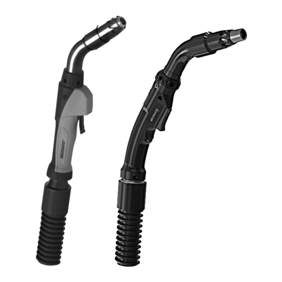
Fume Extraction MIG (GMAW)
Welding Gun
Series
™
Phone: 1-855-MIGWELD (644-9353)
1-519-737-3000
(International)
Fax:
708-946-6726
For more information, visit us at BernardWelds.com
March 2017
(US & Canada)
Advertisement
Table of Contents

Related Manuals for Bernard CLEAN AIR SERIES


Summary of Contents for Bernard CLEAN AIR SERIES
- Page 1 MIG (GMAW) Welding Description Fume Extraction MIG (GMAW) Welding Gun Clean Air Series ™ OWNER’S MANUAL Bernard Phone: 1-855-MIGWELD (644-9353) (US & Canada) A Division of Miller Electric Mfg. Co. 1-519-737-3000 (International) 449 West Corning Road, Box 667 Fax: 708-946-6726 Beecher, Illinois 60401 USA For more information, visit us at BernardWelds.com...
- Page 2 Please read, understand and follow all safety precautions. While every precaution has been taken to assure the accuracy of this owner’s manual, Bernard assumes no responsibility for errors or omissions. Bernard assumes no liability for damages resulting from the use of information contained herein.
-
Page 3: Table Of Contents
2-2 Duty Cycle and Overheating............................SECTION 3 - INSTALLATION......................3-1 Installing to a Feeder with Power Pin......................... 3-2 Installing to a Feeder with a Euro or Bernard Power Pin..................3-3 Installing to a Fume Extraction Unit........................... SECTION 4 - OPERATION....................... -
Page 4: Section 1 - Safety Precautions For Gmaw Welding Guns - Read Before Using
SECTION 1 - SAFETY PRECAUTIONS - READ BEFORE USING 1-1 Fume Extraction Hazards b. You experience dizziness, impaired vision, or eye, nose, or mouth irritation. c. The equipment is damaged. Fume Extraction Misuse can be d. Air flow decreases or stops. dangerous e. -
Page 5: Arc Rays And Welding Hazards
1-2 Arc Rays and Welding Hazards and causing electric shock, sparks, and fire hazards. • Do not use welder to thaw frozen pipes. • Remove stick electrode from holder or cut off welding ARC RAYS can burn eyes and skin. wire at contact tip when not in use. -
Page 6: Additional Safety Warnings For Installation, Operation And Maintenance
situations use of a DC, constant voltage wire welder is stationary support or cylinder rack to prevent falling or recommended. And, do not work alone! tipping. • Disconnect input power or stop engine before installing • Keep cylinders away from any welding, cutting, or other or servicing this equipment. - Page 7 ELECTRIC AND MAGNETIC FIELDS (EMF) • Use only genuine replacement parts from the can affect implanted Medical Devices manufacturer. • Perform maintenance and service according to the Owner’s • Wearers of Pacemakers and other Manuals, industry standards, and national, state/provincial and Implanted Medical Devices should keep local codes.
-
Page 8: California Proposition 65 Warning
1-7 Commercial Warranty fitness for any purpose. Bernard shall not be liable under any circumstances to Buyer, or Product is warranted to be free from defects in material and to any person who shall purchase from Buyer, for damages of any workmanship for 1 Year after the sale by an authorized Buyer. -
Page 9: Section 2 - Specifications
SECTION 2 - SPECIFICATIONS 2-1 Specifications Fume Extraction MIG Welding Gun 300 amp gun feeds maximum wire size of 5/64" Duty Cycle Rating: 100%: 300 Amp with Shielding gas 60%: 300 Amp with Mixed Gases 400 amp gun feeds maximum wire size of 5/64” Duty Cycle Rating: 100%: 400 Amp with Shielding gas... -
Page 10: Section 3 - Installation
2. Insert control plug into feeder. 3. Feed welding wire into power pin by hand and tighten drive rolls. 3-2 Installing to a Feeder with a Euro or Bernard Power Pin Euro 1. Insert the Euro power pin to face of receptacle. -
Page 11: Section 4 - Operation
SECTION 4 - OPERATION 4-1 Pulling the Trigger 1. Trigger - When pressed, energized wire feeds and shielding gas flows. 4-2 Adjusting the Vacuum Chamber 1. Vacuum Chamber - The vacuum chamber can be adjusted to any of four set positions. Adjust the vacuum chamber by pulling it back or pushing it forward until it locks into the desired position. -
Page 12: Section 5 - Replacement
SECTION 5 - REPLACEMENT 5-1 Changing Consumables A. Changing Quik Tip Consumables ™ electrode into the gas diffuser and lock by installing nozzle onto the gas diffuser. Nozzle is used to secure 1. Remove vacuum chamber. contact tip. 2. Remove threaded nozzle by turning in a 4. -
Page 13: Changing The Liner
5-2 Changing the Liner A. Changing Conventional Liner 1. Remove nozzle, contact tip, and gas diffuser/ retaining head and lay cable straight. Using a 10 mm wrench, turn liner lock counterclockwise until it is free from the power pin. Remove liner from gun assembly. -
Page 14: Changing The Neck And Switch
5-3 Changing the Neck and Switch A. Changing the Neck 1. Remove the two top pod screws (A) on the side of the gun. 2. Slide the top pod (B) up and back towards the rear of the handle and pull the trigger housing (C) down. -
Page 15: Changing The Vacuum Hose
5-4 Changing the Vacuum Hose 1. Open the handle and remove the neck and trigger by following the steps listed in the ‘Changing the Neck and Switch’ section 5-3. 2. With a 1/4 counterclockwise rotation, remove the vacuum hose rear cap from the rear strain relief assembly. - Page 16 8. Install strain relief and vacuum hose assembly. 9. Reinstall liner by following the steps listed in the ‘Changing the Liner’ section 5-2. C. Bernard Quick Disconnect 1. Remove the liner by following the steps listed in the ‘Changing the Liner’ section 5-2. Remove vacuum hose assembly.
-
Page 17: Section 6 - Optimizing Fume Capture
SECTION 6 - OPTIMIZING FUME CAPTURE 6-1 Optimizing Fume Capture Follow the diagram below for optimizing the efficiency of fume capture from your fume extraction MIG gun. The joints and positions of welds will affect the efficiency of fume capture. Optimal Optimal capture efficiency is achieved when fume gun is positioned directly above the weld puddle. -
Page 18: Section 7 - Parts List
SECTION 7 - PARTS LIST 7-1 Replacement Parts Page 16... - Page 19 2280069 Screw 2950012 Screw Cover 1010039 Adapter Block (Miller, Lincoln, Tweco) 1010027 Adapter Block (Bernard & Euro) GN2021 Electrical Plug, Non-D/S (Miller, Lincoln,Tweco Power Pins) See Clean Air Spec Sheet* Liner Assy See Clean Air Spec Sheet* Power Pin Components...
- Page 20 BernardWelds.com/TechnicalSupport ..............Scan to view Clean Air Spec Sheet Bernard , Clean Air , Centerfire , Quik Tip and other names are trademarks of Bernard, a division of Miller Electric Mfg. Co. ™ ™ ™ ™ Tregaskiss , TOUGH LOCK and QUICK LOAD are trademarks of Tregaskiss, a division of ITW Canada Inc.
Need help?
Do you have a question about the CLEAN AIR SERIES and is the answer not in the manual?
Questions and answers