Table of Contents
Advertisement
Quick Links
Clean Air
OWNER'S MANUAL
Bernard
A Division of Miller Electric Mfg. LLC
449 West Corning Road
Beecher, Illinois 60401 USA
OM-CA-1.9
Processes
MIG (GMAW) Welding
Description
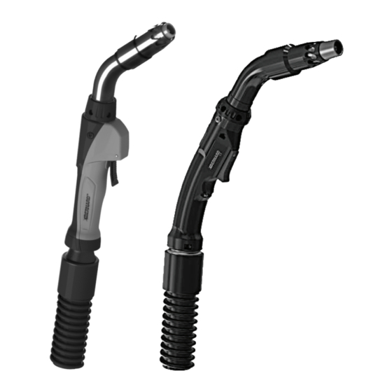
Fume Extraction MIG (GMAW)
Welding Gun
Series
™
Phone: 1-855-MIGWELD (644-9353)
1-519-737-3000
(International)
Fax:
708-946-6726
For more information, visit us at BernardWelds.com
July 2018
(US & Canada)
Advertisement
Table of Contents

Subscribe to Our Youtube Channel
Related Manuals for Bernard Clean Air Series


Summary of Contents for Bernard Clean Air Series
- Page 1 Processes MIG (GMAW) Welding Description Fume Extraction MIG (GMAW) Welding Gun Clean Air Series ™ OWNER’S MANUAL Bernard Phone: 1-855-MIGWELD (644-9353) (US & Canada) A Division of Miller Electric Mfg. LLC 1-519-737-3000 (International) 449 West Corning Road Fax: 708-946-6726 For more information, visit us at BernardWelds.com...
- Page 2 Please read, understand and follow all safety precautions. While every precaution has been taken to assure the accuracy of this owner’s manual, Bernard assumes no responsibility for errors or omissions. Bernard assumes no liability for damages resulting from the use of information contained herein.
-
Page 3: Table Of Contents
SECTION 3 – INSTALLATION ......................9 3-1 Installing to a Feeder with Power Pin ������������������������������������������������������������������������������������������������������������������������������������������9 3-2 Installing to a Feeder with a Euro or Bernard Power Pin �������������������������������������������������������������������������������������������������������������� 9 3-3 Installing to a Fume Extraction Unit���������������������������������������������������������������������������������������������������������������������������������������������9 SECTION 4 – OPERATION ......................10 4-1 Pulling the Trigger ���������������������������������������������������������������������������������������������������������������������������������������������������������������������10... -
Page 4: Declaration Of Conformity
DECLARATION OF CONFORMITY for European Community (CE marked) products. Bernard Welding, 449 West Corning Rd., Beecher, IL 60401 U.S.A. declares that the product(s) identified in this declaration conform to the essential requirements and provisions of the stated Council Directive(s) and Standard(s). -
Page 5: Section 1 - Safety Precautions - Read Before Using
SECTION 1 - SAFETY PRECAUTIONS FOR GMAW WELDING GUNS - READ BEFORE USING Protect yourself and others from injury — read, follow, and save these important safety precautions and operating instructions. 1-1 Symbol Usage DANGER! − Indicates a hazardous situation which, if not avoided, will result in death or serious injury. -
Page 6: California Proposition 65 Warnings
BUILDUP OF GAS can injure or kill. NOISE can damage hearing. • Shut off compressed gas supply when not in Noise from some processes or equipment can use. damage hearing. • Always ventilate confined spaces or use • Check for noise level limits exceeding approved air-supplied respirator. -
Page 7: Principal Safety Standards
Bernard reserves the right to repair, replace or refund the but not limited to, any delay, act, error or omission of Bernard. purchase price of non-conforming product. Product found Genuine Bernard parts must be used for safety and performance not defective will be returned to the Buyer after notification by Customer Service. -
Page 8: Section 2 - Specifications
SECTION 2 - SPECIFICATIONS 2-1 Specifications Fume Extraction MIG Welding Gun 300 amp gun feeds maximum wire size of 5/64" Duty Cycle Rating: 100%: 300 Amp with Shielding gas 60%: 300 Amp with Mixed Gases 400 amp gun feeds maximum wire size of 5/64” Duty Cycle Rating: 100%: 400 Amp with Shielding gas... -
Page 9: Section 3 - Installation
2. Insert control plug into feeder. 3. Feed welding wire into power pin by hand and tighten drive rolls. 3-2 Installing to a Feeder with a Euro or Bernard Power Pin Euro 1. Insert the Euro power pin to face of receptacle. -
Page 10: Section 4 - Operation
SECTION 4 - OPERATION 4-1 Pulling the Trigger 1. Trigger - When pressed, energized wire feeds and shielding gas flows. 4-2 Adjusting the Vacuum Chamber 1. Vacuum Chamber - The vacuum chamber can be adjusted to any of four set positions. Adjust the vacuum chamber by pulling it back or pushing it forward until it locks into the desired position. -
Page 11: Section 5 - Replacement
SECTION 5 - REPLACEMENT 5-1 Changing Consumables A. Changing Quik Tip Consumables ™ electrode into the gas diffuser and lock by installing nozzle onto the gas diffuser. Nozzle is used to secure 1. Remove vacuum chamber. contact tip. 2. Remove threaded nozzle by turning in a counter- 4. -
Page 12: Changing The Liner
5-2 Changing the Liner A. Changing Conventional Liner 1. Remove nozzle, contact tip, and gas diffuser/ retaining head and lay cable straight. Using a 10 mm wrench, turn liner lock counterclockwise until it is free from the power pin. Remove liner from gun assembly. -
Page 13: Changing The Neck And Switch
5-3 Changing the Neck and Switch A. Changing the Neck - Straight Handle Model 1. Remove the two top pod screws (A) on the side Straight Handle Model of the gun. 2. Slide the top pod (B) up and back towards the rear of the handle and pull the trigger housing (C) down. -
Page 14: Changing The Vacuum Hose
C. Changing the Neck - Curved Handle Model Curved Handle Model 1. Remove the vacuum chamber and front end consumables (A). 2. Remove the screws (B) to remove the vacuum tube (C). 3. Remove screws and nuts (F) and gently spread the handle (E) apart, keeping hold of the trigger (G). -
Page 15: Changing The Power Pin
Curved Handle Model B. Vacuum Hose on Curved Handle Model 1. Open the handle and remove the neck. Follow the steps listed in the ‘Changing the Neck and Switch’ section 5-3 C. and D. instructions. 2. With a 1/4 counterclockwise turn, remove the vacuum hose rear cap from the rear strain relief Slide the old vacuum hose forward and remove from the cable. - Page 16 8. Install strain relief and vacuum hose. 9. Reinstall liner by following the steps listed in the ‘Changing the Liner’ section 5-2. C. Bernard Quick Disconnect 1. Remove the liner by following the steps listed in the ‘Changing the Liner’ section 5-2. Remove vacuum hose.
-
Page 17: Section 6 -Optimizing Fume Capture
SECTION 6 - OPTIMIZING FUME CAPTURE 6-1 Optimizing Fume Capture Follow the diagram below for optimizing the efficiency of fume capture from your fume extraction MIG gun. The joints and positions of welds will affect the efficiency of fume capture. Optimal Optimal capture efficiency is achieved when fume gun is positioned directly above the weld puddle. -
Page 18: Section 7 - Parts List
SECTION 7 - PARTS LIST 7-1 Replacement Parts 300, 400, 500, 600 amp with Straight Handle... - Page 19 Screw 2950012 Screw Cover 1010039 Adapter Block (Miller, Lincoln, Tweco) 1010027 Adapter Block (Bernard & Euro) GN2021 Electrical Plug, Non-D/S (Miller, Lincoln,Tweco Power Pins) See Clean Air Gun Spec Sheet* Liner See Clean Air Gun Spec Sheet* Power Pin Components...
-
Page 20: Replacement Parts 300, 400 Amp With Curved Handle
7-2 Replacement Parts 300, 400 amp with Curved Handle... - Page 21 Vacuum Hose Adapter Kit (Includes: (1) 2-1/8” to 1-1/2” threaded hose fitting, (1) #25) Clamp 1010039 Adapter Block (Miller, Lincoln, Tweco) 1010027 Adapter Block (Bernard & Euro) GN2021 Electrical Plug, Non-D/S (Miller, Lincoln,Tweco Power Pins) See Clean Air Gun Spec Sheet* Liner...
- Page 22 NOTES...
- Page 23 BernardWelds.com/TechnicalSupport ..............Scan to view Clean Air Gun Spec Sheet Bernard , Clean Air , Centerfire , Quik Tip and other names are trademarks of Bernard, a division of Miller Electric Mfg. LLC. ™ ™ ™ ™ Tregaskiss ™...
Need help?
Do you have a question about the Clean Air Series and is the answer not in the manual?
Questions and answers