Table of Contents
Advertisement
Quick Links
� SCDSC? 11:·
IN-DASH STEREO
2010-UP CHEVROLET CAMARO
WITH TOUCH-SCREEN INTERFACE
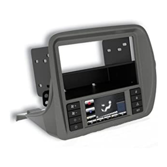
This premium installation kit is for 2010-Up Chevrolet Camaro vehicles. lncluded are all the parts
you need to mount your саг stereo or CD player into your vehicle's dash. Refer to the individual
instruction in this manual to remove your vehicle's factory radio and assemЫe the kit.
CAUTION
DISCONNECT YOUR VEHICLE'S NEGATIVE ВАПЕRУ TERMINAL BEFORE ТНЕ INSTALLATION
ТО HELP PREVENT ELECTRICAL DAMAGE. WE RECOMMEND ТНЕ USE OF А VOLT/OHM
METER OVER А TEST LIGHT ТО СНЕСК WIRING. А TEST LIGHT OR GROUNDED WIRE PROBE
CAN CAUSE DAMAGE ТО ТНЕ VEHICLE'S COMPUTER AND/OR DIAGNOSTIC SYSTEMS. AVOID
ALL FACTORY AIRBAG WIRING - AIRBAGS CAN ACCIDENTALLY DEPLOY CAUSING SERIOUS
INJURY OR DEATH.
NOTES
• See your vehicle's instructions for any special tools your installation might require.
• Read all instructions accompanying your саг stereo for proper wiring and mounting instructions.
This instruction Ьooklet is based оп carefullydocumented data and research of automoblle dash disassemЫy, wire harness/codes
and information pertaining to installation of this kit (GM5201AB) in 2010-Up Chevrolet Camaro vehicles. Scosche lndustries, lnc.
cannot Ье held responsiЫe for discrepancies/inconsistencies that may occur due to the automoblle manufacturing changes or
options, or damage that may occur in the automoblle during the installation of components while using this Ьooklet.
INSTALLATION KIT FOR
INTRODUCTION/PRELIMINARY
LIABILIТY DISCLAIMER
GM5201AB
Advertisement
Table of Contents

Related Manuals for Scosche GM5201AB


Summary of Contents for Scosche GM5201AB
- Page 1 This instruction Ьooklet is based оп carefullydocumented data and research of automoblle dash disassemЫy, wire harness/codes and information pertaining to installation of this kit (GM5201AB) in 2010-Up Chevrolet Camaro vehicles. Scosche lndustries, lnc. cannot Ье held responsiЫe for discrepancies/inconsistencies that may occur due to the automoblle manufacturing changes or...
-
Page 2: Parts List
PARTS LIST 1. Main panel with built-in touch screen (*) 2. Stereo mounting bracket (left) 3. Stereo mounting bracket (right) 4. Dash pocket for single din mount 5. Power harness (not shown-see page 3) cJ cJ / cJ SOLD SEPARATELY: cJ cJ CAMOSM OnStar retention interface... - Page 3 STEREO ASSEMBLY / MOUNTING PANEL SINGLE DIN ISO INSTALLATION 1 . Attach 6552 pocket to the back the of main kit panel with the (2) supplied screws as shown above. 2. Mount the 7147 and 7148 left and right brackets to the sides of the aftermarket stereo using the screws supplied with the stereo as shown below.
- Page 4 STEREO ASSEMBLY / MOUNTING DOUBLE DIN ISO INSTALLATION 1. Mount the 714 7 and 7148 left and right brackets to the sides of the aftermarket stereo using the screws supplied with the stereo. 2. Connect and mount the stereo in the dash. The main kit panel mounts to the dash over the stereo.
- Page 5 2010-up CAMOSM Camaro OnStar retention №,li module (Sold separately) ________ (bypass plug) AFTERMARKET RADIO GM5201AB WIRE COLOR CODES White Left Front Positive (LF+) White/Black Left Front Negative (LF-) Gray Right Front Positive (RF+) Gray/Black Right Front Negative (RF-) Left Rear Positive (LR+)
-
Page 6: Vehicle Startup
OnStar® module*. 5. Move OnStar® module, radio connector, and HVAC connector to the left of the radio cavity. 6. Route the 8 and 24 pin connectors of Scosche harness to original location of HVAC connector. 7. Connect the Scosche harness along with antenna and all other accessories to the aftermarket radio and insert into radio cavity. -
Page 7: Hazard Warning Flashers
CLIMATE & CONVENIENCE CONTROLS FIGURE 2 Home TFT Color Touch Screen layout WARM Temp range COOL 6. Rear Defog 1. AirTemp Up 7. Recirculate 2. Air Temp Down 8. Pass Heated Seat 3. Мах NC On/Off 9. Vent Mode 4. Driver's Heated Seat 1 О. -
Page 8: Temperature Control
CLIMATE & CONVENIENCE CONTROLS (cont.) FAN SPEED CONTROL «А То increase fan speed, press the fan speed UP button оп the control panel (pg. 7, Fig. 1, #1 ). Оп the color ТFТ touch screen а graphic level indicator will move up indicating the current fan speed (pg. -
Page 9: Preview Window
DISPLAY SCREEN SETTINGS FIGUREЗ Settings Home Screen layout Brightness С=] Version Number 1. Display Settings 6. Auto Theme Setting (Vehicle-controlled) 2. Саг Settings 7. Brightness Control (ТFТ screen) 3. Back/Return 8. Preview Window 4. Day Theme Setting (override) Other: Software version number appearson 5. - Page 10 VEHICLE FEATURE / SETTINGS The color ТFТ touch screen interface is used to access the vehicle's built-in customization features. VEHICLE SEПINGS MENU Press the "Set" button (see page 6, Fig. 1, #8) оп the control рапе! to access the user controlled features and settings.
-
Page 11: Steering Wheel Controls
VEHICLE FEATURE / SETTINGS (cont.) VEHICLE FEATURE DETAILS Climate and Air Quality Heated Seats: Оп ог Off when vehicle is remote started Collision/Detection Systems Park Assist feature: ЕnаЫе ог DisaЫe the vehicle's ultrasonic bumper object sensors (Depends оп vehicle options/equipment) Lighting Exit Lighting: Set exterior lights delay when exiting vehicle at night Vehicle Locator Lights: Set exterior lights ON ог... - Page 12 То ensure proper functionality, cycle the ignition key from "Off" to "Run" TWO times (2Х) after first connecting the interface to your vehicle.
Need help?
Do you have a question about the GM5201AB and is the answer not in the manual?
Questions and answers
Ar yra pardavime kokia kaina