Table of Contents
Advertisement
Quick Links
Download this manual
See also:
Installation Manual
Manufacturer:
Model Number(s):
Core Module Version:
Document Revision Date:
O
S
VERVIEW AND
UPPORTED
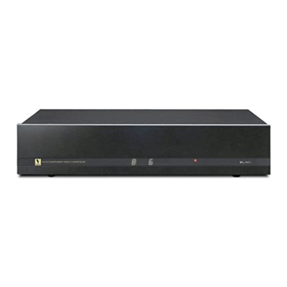
The ELAN V883 and V85 are 8 X 8 Component Video Controller which switches eight
component/composite sources to any of eight component/composite outputs and can connect to the g!
software with a RS-232 serial connection to allow reliable 2-way communication. Up to four V883s or
V85s can be stacked for a total of 32 zone outputs from eight source inputs.
T
HE FOLLOWING FEATURES ARE SUPPORTED
Serial Pass Through: V883/V85 can be connected to the RS-232 output on an ELAN S12 or S8.6, thus
allowing the devices to share a single COM Port on the g! system controller.
Multiple Chassis Configuration: Up to four V883/V85s can be linked together to provide 32 zone
outputs from eight source inputs.
T
HE FOLLOWING FEATURES ARE NOT SUPPORTED
Any feature not specifically noted as supported should be assumed to be unsupported.
I
O
NSTALLATION
VERVIEW
1. During the rough-in phase, install wires for the sources, amplifiers and displays for each zone.
2. Also during the rough-in phase, run a Cat5 wire from the location of the switch back to the Network
Assembly of the g! system for RS-232 communications. Refer to the RS-232 Connection Options
Integration Note for other options.
3. Install the switch, the sources, amplifier, displays and speakers.
4. If using Core Module version 4.0, use VIA!Tools to configure the V883/V85 for proper zone
switching.
5. Confirm proper audio and video switching as a stand alone system.
6. Connect the g! system to the switch electrically. See the wiring diagrams for more information.
7. Configure the g! system for the switch and confirm communication between the switch and the g!
system controller. See g! Configuration Details.
8. Test the system by changing sources in a zone to confirm the correct source plays. Test source
control for any sources that are to be controlled from the g! interface.
ELAN Home Systems ● 1690 Corporate Circle ● Petaluma, CA 94954 USA
tech support: 800.622.3526 • main: 760.710.0990 • sales: 877.289.3526 • email: elan@elanhomesystems.com
©2013 ELAN Home Systems. All rights reserved. ELAN and g! are trademarks of ELAN Home Systems. All other trademarks are the property of their respective owners.
ELAN Home Systems
V883, V85
4.0.1288 and newer (V883)
4.0 1587 and newer (V85)
1/15/2013
F
EATURES
:
:
Integration Note
Advertisement
Table of Contents

Subscribe to Our Youtube Channel
Summary of Contents for Elan V883
- Page 1 ELAN Home Systems ● 1690 Corporate Circle ● Petaluma, CA 94954 USA tech support: 800.622.3526 • main: 760.710.0990 • sales: 877.289.3526 • email: elan@elanhomesystems.com ©2013 ELAN Home Systems. All rights reserved. ELAN and g! are trademarks of ELAN Home Systems. All other trademarks are the property of their respective owners.
- Page 2 ONNECTION IAGRAMS 1: S PTION TAND LONE ATERIALS D e v ic e M a nuf a c t ure r P a rt N um be r P ro t o c o l C o nne c t o r T ype N o t e s Co mpo site Video Cable A nalo g...
- Page 3 PTION LAVE Cat5 Cable Assy Elan S8.6 Video Display RS-232 g! System Controller DB9F to RJ45 Adapter Elan V883 Source Inputs Video Outputs DB9M to RJ45 Adapter RS-232 Component Video Cables Video Display Composite Video Cables Source 1(Serial) Source 2 (IR)
- Page 4 Move any unused zones to the right into Available Zones to remove from the viewer Notes: 1. If multiple Elan Zone Controllers are used, only one communications device is required. 2. Select the appropriate number of zones from the list based on the number of V883/V85 chassis in the configuration. 4 of 5...
- Page 5 OMMON ISTAKES 1. Setting up multiple communication devices when using serial pass-thru from another piece of ELAN gear (such as S12, S8.6). If using serial pass thru only one Communication Device is required. 5 of 5...


Need help?
Do you have a question about the V883 and is the answer not in the manual?
Questions and answers