Table of Contents
Advertisement
Quick Links
Para español, visita:
http://www.generac.com/service-support/product-support-lookup
Pour le français, visiter :
http://www.generac.com/service-support/product-support-lookup
SAVE THIS MANUAL FOR FUTURE REFERENCE
Owner's Manual
50 Hz Air-Cooled Generators
8 kVA to 13 kVA
This product is not intended to be used in
a critical life support application. Failure to
adhere to this warning could result in
death or serious injury.
Register your Generac product at:
WWW.GENERAC.COM
1-888-GENERAC
(888-436-3722)
000918
WARNING
(000209a)
Advertisement
Table of Contents

Related Manuals for Generac Power Systems 8 kVA


Summary of Contents for Generac Power Systems 8 kVA
- Page 1 Owner’s Manual 50 Hz Air-Cooled Generators 8 kVA to 13 kVA 000918 WARNING This product is not intended to be used in a critical life support application. Failure to adhere to this warning could result in death or serious injury.
- Page 2 Use this page to record important information about your generator set. Record the information found on your unit data label on this page. See General Information for the location of the unit Model: data label. The unit has a label plate affixed to the inside partition, to the left of the control panel console as shown in Figure 2-1.
-
Page 3: Table Of Contents
Table of Contents Section 1: Safety Rules & General Setting the Exercise Timer ....... 14 Information Battery Charger ..........14 Introduction ............1 Manual Transfer Operation ....... 14 Read This Manual Thoroughly ........1 Transfer to Generator Power Source ......14 How to Obtain Service ..........1 Transfer to Utility Power Source ........15 Safety Rules ............2 Automatic Transfer Operation ...... - Page 4 Table of Contents Section 5: Troubleshooting / Quick Reference Guide Generator Troubleshooting ......31 Quick Reference Guide ........32 Section 6: Quick Reference Guide System Diagnosis ..........35 Owner’s Manual for 50 Hz Air-Cooled Generators...
-
Page 5: Section 1: Safety Rules & General Information Introduction
Safety Rules & General Information Section 1: Safety Rules & General Information Introduction WARNING Thank purchasing this compact, high Indicates a hazardous situation which, if not avoided, performance, air-cooled, engine-driven generator. It is could result in death or serious injury. designed to automatically supply electrical power to operate critical loads during a utility power failure. -
Page 6: Safety Rules
Safety Rules & General Information Safety Rules WARNING Study these SAFETY RULES carefully before installing, operating, or servicing this equipment. Become familiar with this owner’s manual and with the unit. The generator can operate safely, efficiently, and reliably only if it is (000182) properly installed, operated, and maintained. -
Page 7: Exhaust Hazards
Safety Rules & General Information Electrical Hazards WARNING DANGER Environmental Hazard. Always recycle batteries at an official recycling center in accordance with all local Electrocution. Contact with bare wires, laws and regulations. Failure to do so could result in terminals, and connections while generator environmental damage, death or serious injury. -
Page 8: Fire Hazards
Safety Rules & General Information Fire Hazards Explosion Hazards DANGER WARNING Fire hazard. Do not obstruct cooling and ventilating airflow around the generator. Inadequate ventilation could result in fire hazard, possible equipment damage, death or serious injury. (000217) (000192) DANGER WARNING Connection of fuel source must be done by a qualified Fire and explosion. -
Page 9: Section 2: General Information
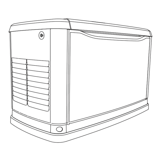
General Information Section 2: General Information The Generator 001786 Figure 2-1. Components and Control Locations Lock with Cover Battery Compartment Oil Fill Cap Sediment Trap (Battery not supplied) Main Line Circuit Exhaust Enclosure Oil Filter Fuel Regulator Breaker (Generator Disconnect) Airbox with Air Cleaner Status LED Indicators Composite Base... -
Page 10: Specifications
General Information Specifications Generator Model 8 kVA 10 kVA 13 kVA Rated Voltage 220/230/240 Rated Maximum Load Current (Amps) at Rated 36.4 / 34.8 / 33.3 45.5 / 43.5 / 41.7 59.1 / 56.5 / 54.2 Voltage* Main Circuit Breaker... -
Page 11: Protection Systems
General Information Protection Systems Fuel Requirements DANGER The generator may need to run for long periods of time with no operator present to monitor the engine/generator Explosion and Fire. Fuel and vapors are conditions. The generator is equipped with protection extremely flammable and explosive. -
Page 12: Replacement Parts
General Information Replacement Parts Description 8 kVA 10 kVA 13 kVA 26R Exide Battery 0H3421S 0E9368 0E7585A Spark Plug (RL87YC or equivalent) (RC14YC4 or equivalent) Oil Filter 070185E Air Filter 0E9371A 0J8478 Control Panel Fuse 0D7178T Transfer Switch Fuses 073590A Accessories NOTE: Performance enhancing accessories are available for air-cooled generators. -
Page 13: Section 3: Operation
Operation Section 3: Operation Site Prep Verification 1. Cut the plastic bag to remove the keys. 2. Use the keys to open the lid of the generator. The generator must be installed so that airflow into and NOTE: The enclosed keys provided with this unit are out of the generator is not impeded. -
Page 14: Intake Side Panel Removal
Operation Intake Side Panel Removal 3. Lift the intake panel up and away from the generator. Figure 3-2. The intake side panel (A) must be NOTE: Always lift the intake side panel straight up removed to access the battery compartment, fuel before pulling away from enclosure. -
Page 15: Control Panel Interface
Operation Control Panel Interface Interface Menu Displays Figure 3-5. The control panel interface (A) is located The LCD Panel under the lid of the enclosure. Verify that both the left and right side locks are unlocked before attempting to lift the lid of the enclosure. -
Page 16: Menu System Navigation
Operation Menu System Navigation To get to the MENU, use the ESCAPE button from any page. You may need to press the ESCAPE button several times ↑ ↓ before reaching the MENU page. Navigate to the desired menu by using the buttons. -
Page 17: Owner's Manual For 50 Hz Air-Cooled Generators
Operation Current Date/Time UP ARROW = 02/14/16 07:40 (mm/dd/yy hr:min format) DOWN ARROW = ENTER Run Hours (H) ENTER MAINT: Run Hrs ENTER Maint. Log Scheduled DEALER Access Requires Password ENTER ENTER - 1 thru 50 + EXAMPLE: "Battery Maintained" Inspect Battery 200 RnHr or 12/27/16 "Schedule A Serviced"... -
Page 18: Setting The Exercise Timer
Operation Setting the Exercise Timer Manual Transfer Operation This generator is equipped with a configurable exercise DANGER timer. There are two settings for the exercise timer: Electrocution. Do not manually transfer under load. Day/Time: The generator will start and exercise for the Disconnect transfer switch from all power sources period defined, on the day of the week and at the time of day prior to manual transfer. -
Page 19: Transfer To Utility Power Source
Operation • Will not transfer to generator if utility is present. • Will transfer to generator if utility fails (below 65% of nominal for five consecutive seconds) MANUAL after warm-up. • Will transfer back when utility returns for 15 consecutive seconds. The engine will continue to run until removed from the MANUAL mode. -
Page 20: Automatic Sequence Of Operation
Operation Automatic Sequence of Operation The cleaning cycle is an extended warming up period which lasts for several minutes while the normal genera- tor voltage output is determined to be low. During this Utility Failure cycle, the generator controller will display “Warming Up” If the generator is set to AUTO, when utility fails (below on the display screen. -
Page 21: Section 4: Maintenance
Section 4: Maintenance Maintenance Performing Scheduled Maintenance Regular maintenance will improve performance and extend engine/equipment life. Generac Power Systems, It is important to perform maintenance as specified in the Inc. recommends that all maintenance work be Service Schedule for proper generator operation. -
Page 22: Service Schedule
Maintenance Service Schedule Schedule A Schedule B Daily If Running Continuously Every Service Every Two Years Every Four Years or Before Each Use Year or 200 Hours or 400 Hours ● Check enclosure louvers for dirt and debris * ● Check lines and connections for fuel or oil leaks ●... -
Page 23: Checking Engine Oil Level
Maintenance Checking Engine Oil Level Engine Oil Requirements To maintain the product warranty, the engine oil should WARNING be serviced in accordance with the recommendations of this manual. your convenience, Generac Risk of burns. Allow engine to cool before Maintenance Kits are available that include engine oil, oil draining oil or coolant. -
Page 24: Changing The Oil And Oil Filter
Maintenance Changing the Oil and Oil Filter Servicing the Air Cleaner Proceed as follows to change the oil and oil filter: Proceed as follows to service the air cleaner: 1. Press the MANUAL button on the control panel to 1. Press the OFF button on the control panel to stop the start the engine, and run it until it is thoroughly generator. -
Page 25: Valve Clearance Adjustment
Maintenance NOTE: Allow engine to cool before adjusting valve clearance. 1. Remove spark plug wires and position wires away from plugs. 2. Remove spark plugs. 3. Remove the four screws attaching the valve cover. Remove and discard gasket. 4. Make sure the piston is at top dead center (TDC) of its compression stroke (both valves closed). -
Page 26: Battery Maintenance
Maintenance Battery Maintenance WARNING The battery should be regularly inspected per the Electrical shock. Disconnect battery ground Service Schedule. Contact an IASD for assistance if terminal before working on battery or battery necessary. wires. Failure to do so could result in death or serious injury. -
Page 27: Cleaning The Sediment Trap
Maintenance • be any electrical problems during generator operation or DO NOT smoke when near the battery. when utility power is returned. • DO NOT cause flame or spark in the battery area. • Discharge static electricity from the body before Corrosion Protection touching the battery by first touching a grounded metal surface. -
Page 28: Return To Service
Maintenance 11. Remove the battery and store it in a cool, dry room on a wooden board. 12. Clean and wipe down the entire generator. Return to Service Proceed as follows to return the unit to service after storage: 1. Verify utility power is off. 2. - Page 29 Troubleshooting / Quick Reference Guide Section 5: Troubleshooting / Quick Reference Guide Generator Troubleshooting Problem Cause Correction Engine will not 1. Blown fuse. 1. Correct short circuit condition by replacing 7.5 crank. amp fuse in generator control panel. Contact an Independent Authorized Service Dealer (IASD) if fuse continues to blow.
-
Page 30: Quick Reference Guide
Troubleshooting / Quick Reference Guide Quick Reference Guide To clear an active alarm, press the OFF button, the ENTER button, and then press AUTO. If the alarm reoccurs, contact an IASD. Active Alarm Problem Things to Check Solution FLASHING Unit running in AUTO but NONE Check MLCB. - Page 31 Troubleshooting / Quick Reference Guide Active Alarm Problem Things to Check Solution Unit will not start in Check the LEDs / MISWIRE Contact an IASD. AUTO with utility loss. screen for alarms. Unit will not start in Check the LEDs / OVERVOLTAGE Contact an IASD.
- Page 32 Troubleshooting / Quick Reference Guide This page intentionally left blank. Owner’s Manual for 50 Hz Air-Cooled Generators...
- Page 33 Quick Reference Guide Section 6: Quick Reference Guide System Diagnosis To clear an active alarm, press the ENTER button twice and then press AUTO. If the alarm reoccurs, contact an Independent Authorized Service Dealer (IASD). Table 6-1. System Diagnosis Active Alarm Problem Things to Check Solution...
- Page 34 Quick Reference Guide Table 6-1. System Diagnosis (Continued) Active Alarm Problem Things to Check Solution Unit will not start in Check the LED’s / UNDERSPEED Contact an IASD. AUTO with utility loss. Screen for alarms. STEPPER Unit will not start in Check the LED’s / Contact an IASD.
- Page 36 Part No. 0L6635 Rev. A 08/19/16 Generac Power Systems, Inc. ©2016 Generac Power Systems, Inc. All rights reserved S45 W29290 Hwy. 59 Specifications are subject to change without notice. Waukesha, WI 53189 No reproduction allowed in any form without prior written 1-888-GENERAC (1-888-436-3722) consent from Generac Power Systems, Inc.
Need help?
Do you have a question about the 8 kVA and is the answer not in the manual?
Questions and answers