Table of Contents
Advertisement
Quick Links
Owner's Manual
Australian 50 Hz Air-Cooled Generator Sets
8 kVA to 13 kVA
WARNING
Loss of life. This product is not intended to
be used in a critical life support application.
Failure to adhere to this warning could result
in death or serious injury.
(000209b)
Register your Generac product at:
www.generac.com/au
+61 2 8106 3100
SAVE THIS MANUAL FOR FUTURE REFERENCE
Advertisement
Table of Contents

Subscribe to Our Youtube Channel
Related Manuals for Generac Power Systems 8 kVa


Summary of Contents for Generac Power Systems 8 kVa
- Page 1 Owner’s Manual Australian 50 Hz Air-Cooled Generator Sets 8 kVA to 13 kVA WARNING Loss of life. This product is not intended to be used in a critical life support application. Failure to adhere to this warning could result in death or serious injury.
- Page 2 Use this page to record important information about this generator set. Record the information found on the unit data label on this page. See General Information for the location of unit data Model: label. The unit has a label plate affixed to the inside partition, to the left of the control panel console as shown in Figure 2-1.
-
Page 3: Table Of Contents
Table of Contents Section 1: Safety Rules & General Menu System Navigation ........16 Information Setting the Exercise Timer ....... 18 Introduction ............1 Battery Charger ..........18 Read This Manual Thoroughly ........1 Operating Modes ..........19 Safety Rules ............1 Transfer Switch Operation ....... 19 How to Obtain Service ..........2 Automatic Sequence of Operation .... - Page 4 Table of Contents This page intentionally left blank. Owner’s Manual for Australian 50 Hz Air-Cooled Generators...
-
Page 5: Section 1: Safety Rules & General Information
Safety Rules & General Information Section 1: Safety Rules & General Information Introduction Safety Rules Thank you for purchasing this compact, high perfor- The manufacturer cannot anticipate every possible cir- mance, air-cooled, engine-driven generator set. It is cumstance that might involve a hazard. The alerts in this designed to automatically supply electrical power to oper- manual, and on tags and decals affixed to the unit, are ate critical loads during a utility power failure. -
Page 6: How To Obtain Service
Safety Rules & General Information How to Obtain Service WARNING When the generator set requires servicing or repairs, contact an IASD for assistance. Service technicians are Equipment damage. Only qualified service personnel may factory trained and are capable of handling all service install, operate, and maintain this equipment. -
Page 7: Exhaust Hazards
Safety Rules & General Information Electrical Hazards WARNING DANGER Environmental Hazard. Always recycle batteries at an official recycling center in accordance with all local Electrocution. Contact with bare wires, laws and regulations. Failure to do so could result in terminals, and connections while generator environmental damage, death, or serious injury. -
Page 8: Fire Hazards
Safety Rules & General Information Fire Hazards Explosion Hazards DANGER WARNING Fire hazard. Do not obstruct cooling and ventilating Explosion and fire. Fuel and vapors are extremely airflow around the generator. Inadequate ventilation flammable and explosive. No leakage of fuel is could result in fire hazard, possible equipment permitted. - Page 9 Safety Rules & General Information WARNING Electrical shock. Disconnect battery ground terminal before working on battery or battery wires. Failure to do so could result in death or serious injury. (000164) WARNING Risk of burns. Batteries contain sulfuric acid and can cause severe chemical burns.
- Page 10 Safety Rules & General Information This page intentionally left blank. Owner’s Manual for Australian 50 Hz Air-Cooled Generators...
-
Page 11: Section 2: General Information
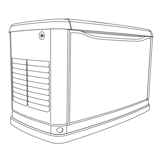
General Information Section 2: General Information Generator Set Components and Controls 001363 Figure 2-1. 8 kVA—Components and Control Locations Lock with cover Exhaust enclosure Composite base Fuel regulator vents (2) Main line circuit breaker (MLCB) (generator set Status LED indicators... - Page 12 General Information 002708 Figure 2-2. 10 kVA and 13 kVA—Components and Control Locations Lock with cover Exhaust enclosure Composite base Fuel inlet MLCB (generator set Status LED indicators Data plate location Fuel regulator vents (2) disconnect) Airbox with air cleaner Oil drain Sediment trap Wi-Fi module...
-
Page 13: Data Decals
General Information Data Decals Two decals on the unit provide information about the unit itself and required fuel inlet pressure for correct operation. Model Data Decal Includes important information about the unit including: • model number • serial number • production date •... -
Page 14: Specifications
General Information Specifications Generator Set Model 8 kVA 10 kVA 13 kVA Rated voltage 220 / 230 / 240 Rated maximum load current (a) at rated 36.4 / 34.8 / 33.3 45.5 / 43.5 / 41.7 59.1 / 56.5 / 54.2... -
Page 15: Protection Systems
General Information Protection Systems Fuel Requirements The generator set may need to run for long periods of time with no operator present to monitor engine/genera- DANGER tor set conditions. The generator set is equipped with Explosion and Fire. Fuel and vapors are extremely protection systems to automatically shut down unit to flammable and explosive. -
Page 16: Replacement Parts
General Information Replacement Parts Description 8 kVA 10 kVA 13 kVA 26R Exide battery 0H3421S 0E9368 0G0767A Spark plug (RL87YC or equivalent) (RC12YC or equivalent) Oil filter 070185E Air filter 0E9371A 0J8478 Control panel fuse 0D7178T Transfer switch fuses See transfer switch manual for part number Accessories NOTE: Performance enhancing accessories are available for air-cooled generator sets. -
Page 17: Section 3: Operation
Operation Section 3: Operation Site Prep Verification operate in or be subjected to standing water. Verify all potential water sources such as water sprinklers, roof run-off, rain gutter downspouts, and sump pump dis- DANGER charges are directed away from generator set enclosure. Loss of life. -
Page 18: Front Access Panel Removal
Operation Front Access Panel Removal 3. Lift intake side panel up and away from generator set. Figure 3-2. Remove front access panel (A) by lifting it straight up and out once lid is open. NOTE: Always lift intake side panel straight up before pulling away from enclosure. -
Page 19: Led Indicator Lights
Operation LED Indicator Lights All appropriate panels must be in place during any opera- tion of generator set. This includes operation by a servic- Figure 3-5. Three LEDs are visible behind a translu- ing technician while conducting troubleshooting pro- cent lens on the generator set side panel. These LEDs cedures. -
Page 20: Menu System Navigation
Operation Menu System Navigation To get to MENU, use ESCAPE button from any page. Multiple presses of ESCAPE button may be required before ↑ ↓ reaching MENU page. Navigate to desired menu by using buttons. Press ENTER button when desired menu is dis- played and flashing. - Page 21 Operation Figure 3-8. Navigation Menu Owner’s Manual for Australian 50 Hz Air-Cooled Generators...
-
Page 22: Setting The Exercise Timer
Operation Setting the Exercise Timer Battery Charger This generator set is equipped with a configurable exer- NOTE: Battery charger is integrated into control module cise timer. There are two settings for the exercise timer: in all models. • Day/Time: Generator set will start and exercise for Battery charger operates as a smart charger that verifies: period defined, on the day of the week and at time •... -
Page 23: Operating Modes
Operation Operating Modes Mode Description • MANUAL Will not transfer to generator set if mains power is present. • Will transfer to generator set if mains power drops (below 156V for five consecutive seconds—dealer program- mable) after warm-up. • Will transfer back when mains power returns for 15 consecutive seconds (dealer programmable). Engine will continue to run until removed from MANUAL. -
Page 24: Cold Smart Start
Operation Shutting Generator Set Down While Cold Smart Start Under Load or During a Utility Outage The generator set will monitor ambient temperature when Cold Smart Start is enabled. The warm-up delay will be adjusted based on prevailing conditions. DANGER The Cold Smart Start feature is factory-enabled, but can Automatic start-up. -
Page 25: Section 4: Maintenance
Performing Scheduled Maintenance Regular maintenance will improve performance and It is important to perform maintenance as specified in the extend engine/equipment life. Generac Power Systems, Service Schedule for correct generator set operation. Inc. recommends all maintenance work be performed by Engine oil and oil filter must be changed, and valve clear- an IASD. - Page 26 Maintenance Service Schedule Daily If Running Schedule A Schedule B Every Service Continuously or Every Two Years Every Four Years Year Before Each Use or 200 Hours or 400 Hours Inspect enclosure louvers for dirt and debris * ● Inspect lines and connections for fuel or oil leaks ●...
-
Page 27: Checking Engine Oil Level
Maintenance Checking Engine Oil Level Engine Oil Requirements CAUTION WARNING Engine damage. Verify proper type and quantity of Risk of burns. Allow engine to cool before engine oil prior to starting engine. Failure to do so draining oil or coolant. Failure to do so could could result in engine damage. -
Page 28: Servicing The Air Cleaner
Maintenance 8. Press MANUAL button on control panel to start 8. Verify air inlet duct (D) is correctly connected to air engine. Run for one minute, and inspect for leaks. cleaner cover. 9. Press OFF button on control panel to stop engine. 9. -
Page 29: Valve Clearance Adjustment
4-4. Loosen rocker jam nut (D) using a front of the engine to access the flywheel nut. Use a large 10mm wrench (8 kVA units) or 13mm wrench (10– socket and socket wrench to rotate flywheel nut clock- 13 kVA units). -
Page 30: Battery Maintenance
Tighten jam nut to specification required in Electrical shock. Disconnect battery ground chart below: terminal before working on battery or battery 8 kVA 8.2 Nm (72 in-lbs) wires. Failure to do so could result in death or serious injury. -
Page 31: Inspecting The Battery
Maintenance • If electrolyte contacts skin, wash it off immediately with water. • If electrolyte contacts eyes, flush thoroughly with water immediately and seek medical attention. • Wash down spilled electrolyte with an acid neutral- izing agent. A common practice is to use a solution of 454 g (1 lb) bicarbonate of soda to 3.8 L (1 gal) of water. -
Page 32: Post Maintenance Checks
Maintenance 4. Use a clean-out tool (not provided) to remove accumulated moisture and particles from sediment trap cap and body (B). 5. Wipe inside of each component with a clean, dry, lint-free cloth. 6. Seal threads of sediment trap cap with appropriate sealing compound. -
Page 33: Remove From, And Return To Service Procedure
Maintenance Remove From, and Return To Service Return to Service Procedure WARNING Remove From Service Explosion. Batteries emit explosive gases. Always connect positive battery cable first to WARNING avoid spark. Failure to do so could result in death or serious injury. Explosion. - Page 34 Maintenance This page intentionally left blank. Owner’s Manual for Australian 50 Hz Air-Cooled Generators...
-
Page 35: Section 5: Troubleshooting/Quick Reference Guide
Troubleshooting/Quick Reference Guide Section 5: Troubleshooting/Quick Reference Guide Generator Set Troubleshooting Problem Cause Correction Correct short circuit condition by replacing 7.5A fuse Blown fuse. in generator set control panel. Contact an IASD if fuse continues to blow. Loose, corroded, or faulty battery cables. Engine will not crank Tighten, clean, or replace as necessary. - Page 36 Troubleshooting/Quick Reference Guide Problem Cause Correction Generator set MLCB (generator set disconnect) is Set generator set MLCB (generator set disconnect) OFF (OPEN). to ON (CLOSED). Faulty transfer switch coil. No transfer to Faulty transfer relay. standby after mains Contact an IASD.
-
Page 37: Quick Reference Guide
Troubleshooting/Quick Reference Guide Quick Reference Guide To clear an active alarm, press OFF button on control panel, then ENTER button, and finally AUTO button. If alarm reoccurs, contact an IASD. Active Alarm Problem Action Solution Check generator set FLASHING Unit running in AUTO but Check generator set MLCB (generator set NONE MLCB (generator set... - Page 38 Troubleshooting/Quick Reference Guide Active Alarm Problem Action Solution Unit will not start in Check LEDs / screen OVERVOLTAGE Contact an IASD. AUTO with utility loss. for alarms. Clear alarm. Using control panel, check battery by navigating to BATTERY MENU Yellow LED illuminated in Check screen for option from the MAIN MENU.
- Page 40 S45 W29290 Hwy. 59 All rights reserved. Waukesha, WI 53189 Specifications are subject to change without notice. AUS: +61 2 8106 3100 No reproduction allowed in any form without prior written USA: 1-262-544-4811 consent from Generac Power Systems, Inc. www.generac.com/au...
Need help?
Do you have a question about the 8 kVa and is the answer not in the manual?
Questions and answers