Table of Contents
Advertisement
Quick Links
Advertisement
Table of Contents

Related Manuals for Galletti WH SERIES


Summary of Contents for Galletti WH SERIES
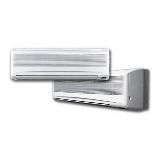
- Page 1 High wall fan coil units TECHNICAL MANUAL HIGH WALL FAN COIL UNITS...
-
Page 2: Declaration Of Conformity
REMOTE CONTROL FUNCTION ..........3 RATED TECHNICAL DATA ............ 3 Coupled with Galletti water chillers and heat pumps, they provide an environmentally friendly alternative to direct expansion systems. SOUND LEVELS ..............4 WH fan coils are hallmarked by the quality of their components and their COOLING CAPACITY ............ -
Page 3: Remote Control Function
REMOTE CONTROL FUNCTION REMOTE CONTROL FUNCTIONS COOLING If the room temperature is lower than the setting temperature, the If the room temperature is higher than the set temperature, the cooling heating mode is activated. The motor driven valve is triggered. The mode is activated. -
Page 4: Sound Levels
SOUND LEVELS Fan speed Octave band sound power level A - weighted sound power level A - weighted sound pressure level (1,5 m distance, 2 directional factor) 125 Hz 250 Hz 500 Hz 1000 Hz 2000 Hz 4000 Hz 8000 Hz dB/A dB/A high... -
Page 5: Heating Capacity
HEATING CAPACITY Legend: Inlet air temperature dry bulb Dpw Pressure drop on water side Inlet water temperature Heating capacity Outlet water temperature Water flow rate Fan speed: high medium 20°C / Tw 45 / 40°C 60°C / 50°C 70°C / 60°C 2640 4130 5340... -
Page 6: Overall Dimensions
OVERALL DIMENSIONS Rear panel with water valve (optionals) 1020 1160 BACK VIEW 1020 1160 INSTALLATION CLEARANCE REQUIREMENTS ceiling higher than eye level floor SY66000120 - 03 All copying, even partial, of this manual is strictly forbidden... -
Page 7: Wiring Diagrams
WIRING DIAGRAMS LEGEND: JP1: NO JUMPER FOR UNIT WITHOUT MOTORIZED VALVE JP1: JUMPER FOR UNIT WITH MOTORIZED VALVE REC MOD (RECEIVER) WH 10 SY66000120 - 03 All copying, even partial, of this manual is strictly forbidden... - Page 8 WIRING DIAGRAMS WH 20 - 30 SY66000120 - 03 All copying, even partial, of this manual is strictly forbidden...
Need help?
Do you have a question about the WH SERIES and is the answer not in the manual?
Questions and answers