Table of Contents
Advertisement
Quick Links
Advertisement
Table of Contents

Related Manuals for Dinstar MMTG200


Summary of Contents for Dinstar MMTG200
- Page 1 MMTG200 Trunk Gateway User Manual V2.0...
- Page 2 MTG200 Trunk Gateway User Manual Revision Records File Name MTG200 Trunk Gateway User Manual Document Version Firmware Version 1/2.01.04.03 Date 17/04/2014 Revised by Technical Support Department...
-
Page 3: Table Of Contents
MTG200 Trunk Gateway User Manual Content 1. PRODUCT INTRODUCTION 1.1 Overview 1.2 Equipment Structure 1.2.1 Rear View 1.2.2 Front View 1.2.3 RJ-48c Line sequence 1.3 Functions and Features 1.3.1 Protocol standard supported 1.3.2 System Function 1.3.3 Industrial standards supported 1.3.4 General hardware specification 2. - Page 4 MTG200 Trunk Gateway User Manual 2.9 SIP Config 2.9.1 SIP Parameter 2.9.2 SIP Trunk 2.10 IP Group Config 2.10.1 IP Profile 2.11 Voice & Fax 2.12 Maintenance 2.12.1 Management Parameter 2.12.2 Data Restore 2.12.3 Data Restore 2.12.4 Version Information 2.12.5 Firmware Upload 2.12.6 Password Modification 2.12.7 Device Restart 3.
-
Page 5: Product Introduction
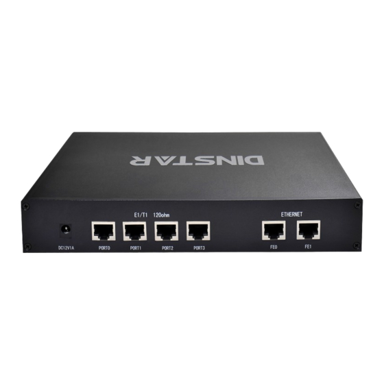
MMTG202-2E1: two ports E1/T1 trunk gateway • MMTG204-4E1: four ports E1/T1 trunk gateway • Notes: MMTG200 support ISDN PRI by default, need to apply new license to enable SS7/R2 if necessary. 1.2 Equipment Structure 1.2.1 Rear View Figure 1-2-1 MTG200 Rear View... -
Page 6: Front View
MTG200 Trunk Gateway User Manual Table 1-2-1 MTG200 Rear View Description Interface Description The power interface. DC12V.1A Port0-Port3 E1/T1 Port. There are 4E1 options. The Service Ethernet Interface, standard 10/100BASE-TX Ethernet interfaces. Default IP address is 192.168.1.111 d efault subnet mask is 255.255.255.0 ,... -
Page 7: Rj-48C Line Sequence
MTG200 Trunk Gateway User Manual Indicating the connection On: Network connection normal, and 0 indicates FE0 state of the network and 1 indicates FE1 Indicating the network Off:10Mbps bandwidth bandwidth SPEED Yellow On:100Mbps bandwidth 1.2.3 RJ-48c Line sequence MTG200 trunk gateway adopts standard RJ-48C interface and impedance value is 120Ω. Connected end device by cross lines sequence. -
Page 8: Industrial Standards Supported
MTG200 Trunk Gateway User Manual ● T.38/ Pass-Through FAX over IP ● HTTP/Telnet configuration ● Firmware upgrade by TFTP/Web 1.3.3 Industrial standards supported ● Stationary use environment: EN 300 019: Class 3.1 ● Storage environment: EN 300 019: Class 1.2 ●... -
Page 9: Parameter Setting
MTG200 Trunk Gateway User Manual 2. Parameter setting 2.1 Login First, device FE0 port connect PC with string, and then fill FE0 IP address in browser, FE0 default IP address is 192.168.1.111. It will request customer to input user name and password. Default user name and password are “admin”. -
Page 10: Status &Statistics
MTG200 Trunk Gateway User Manual Status &Statistics Users through to traverse the left navigation tree, and can complete view, edit and configuration device in the right configuration interface. TG configuration flow chart below:... -
Page 11: System Information
MTG200 Trunk Gateway User Manual 2.2.1 System Information This configuration page includes general information and version information. Figure 2-2-1 System Information Table 2-2-1 Description of System Information MAC address Hardware address of FE0 port Service Ethernet Mode Network mode of FE0, include: static and DHCP. Service Ethernet Interface Include: IP address, subnet mask, FE0 port default gateway Management Ethernet Interface... - Page 12 MTG200 Trunk Gateway User Manual Table 2-2-2 Description of E1/T1 status 1. LOS Alarm: Signal loss alarm, this alarm is created when receiving is lost; please check the physical connection whether disconnected. 2. RAI Alarm: Receive remote alarm indication, it is a signal transmitted in the outgoing direction when a terminal determines that it has lost the incoming signal.
-
Page 13: Pstn Trunk Status
MTG200 Trunk Gateway User Manual 8.R-blocked: Remote blocked, means that communication can only be initiated from remote 9.B-blocked: Both Sides blocked, means that the two sides cannot communication 2.2.3 PSTN Trunk Status Figure 2-2-3 PSTN Trunk Status Table 2-2-3 Description of PSTN Trunk Status PRI Trunk No The number of PRI trunk, each trunk corresponds to a PRI link Trunk Name... -
Page 14: Pri Call Statistics
MTG200 Trunk Gateway User Manual Register Status Indicate the status of SIP trunk ( a ccess mode ) , register or unregister, when is under peer to peer mode, the values is meaningless, as '---' Link Status Established and Fault status. 2.2.5 PRI Call Statistics Figure 2-2-5 PRI Trunk Call Statistics Table 2-2-5 PRI Description of PRI call statistics... -
Page 15: Network
MTG200 Trunk Gateway User Manual Table 2-2-6 Description of SIP Call Statistics SIP Trunk No The number of SIP trunk Trunk Name The name used to describe the PRI trunk Current Calls Number of lines that are being called currently 2.3 Network Figure 2-3-1 Network Configuration Table 2-3-1 Description of Network Configuration... -
Page 16: Pri Config
MTG200 Trunk Gateway User Manual Interface (FE0) Use the following IP If Selected ,Set a static IP for Service Ethernet Interface .Need address to fill the IP address, Subnet Mask, and Default Gateway If users approach the net via PPPoE, please Select it and fill your PPPoE account and password. -
Page 17: Pri Trunk
MTG200 Trunk Gateway User Manual Four options available: User provider, no shield; User provide, check and Screening Indicator for Displaying send; User provide, check and having failure; Network provide. The default option is: User provider, no shield. Caller Number Four options available: User provider, no shield; User provide, check and Screening Indicator for No Displaying send;... -
Page 18: Ss7 Config (Optional)
MTG200 Trunk Gateway User Manual The number of PRI trunk; when user add PRI trunk, 0~7 number will appear in the pull- down menu to be selected (the number here depends on E1/T1 physical port number actually existed in equipment). After trunk number is established, filling in Trunk No corresponding port number in “E1/T1 Port No.”, so as to assign E1/T1 to designated trunk;... - Page 19 MTG200 Trunk Gateway User Manual SS7 is a standard protocol to initiate a calling connection with SPC exchange. Notes: 1. “Trunk No.” is a shared data, therefore, SS7 „Trunk No.‟ can't be the same as PRI “Trunk No.” 2. SPC length is 24bits when option “ANSI” or “ITU-CHINA” is selected in item “Standard Type”.
-
Page 20: Ss7 Mtp Link
MTG200 Trunk Gateway User Manual Trunk Name Name of trunk, it can be edited to any name user want. Protocol SPC types: ITU-T (14 bit), ANSI (24 bit), ITU-CHINA (24 bit) Protocol Type Supported two protocol types: ISUP and TUP Signaling Point Code format includes hexadecimal system and ITU pointcode SPC Format structure (decimal system) -
Page 21: Ss7 Circuit
MTG200 Trunk Gateway User Manual Figure 2-6-5 SS7 MTP Link Add SS7 MTP link description Trunk No It is consistent with foregoing “Trunk No” of SS7 trunk. Equipment maximum support 2 signaling links, these two links share workload, when one link fails, the other link will take over the load until restore from failure, and then they will Link No share the load again. -
Page 22: Ss7 Circuit Maintain
MTG200 Trunk Gateway User Manual Figure 2-6-6 SS7 Circuit description CIC (circuit identification code) is an important parameter of SS7 circuit. It should be confirmed with service provider. If the CIC is mismatched, it will result in one-way voice communication. SS7 Circuit Add Trunk No The “Trunk No.”... - Page 23 MTG200 Trunk Gateway User Manual Figure 2-6-7 SS7 Circuit Maintain-E1/T1 SS7 Circuit Maintain-E1/T1 description Operation Mode There are port operation and channel optional Port No Display the port number Protocol Type TUP or ISUP Status There are 16 status with ports, each state corresponds to a color: activated, disable, fault, RAI Alarm, ISDN/SS7 Signal Alarm, Frame-Sync, Idle, Signal, Busy, L-blocked, R-blocked, B- blocked, Blocking, Unblocking and Resetting.
- Page 24 MTG200 Trunk Gateway User Manual Figure 2-6-8 SS7 Circuit Maintain-Channel If user wants to manage the channel, please select operation mode to channel. Select current port, use will see port status and protocol type. The following will show the slot and channel status.
-
Page 25: R2 Config(Optional)
MTG200 Trunk Gateway User Manual 2.7 R2 Config(optional) 2.7.1 R2 Param Figure 2-7-1 R2 Parameter It is the default configuration for MTG200. Description says the state name, means the different countries supported R2 parameters standards. According to demands add R2 parameters of user countries. - Page 26 MTG200 Trunk Gateway User Manual Figure 2-7-2 R2 Parameter Add...
-
Page 27: R2 Trunk
MTG200 Trunk Gateway User Manual Parameter Description Param ID Identification parameter group Description Description parameter information, Points out which countries standard the parameters are. CDbits C, Dbit value of A, B, C,Dbit in R2 lines of signaling. Request Next The rear party notices the front party ahead called number has received, and each other can send a next number. -
Page 28: Pstn Group Config
MTG200 Trunk Gateway User Manual E1 Port No According to T1 / E1 port position sequence sort, usually starting from 0 Protocol Param Select R2 parameter group. 2.8 PSTN Group Config 2.8.1 E1/T1 Parameter Figure 2-8-1 E1/T1 Parameter Modify the E1/T1 parameters: Figure 2-8-2 E1/T1 Parameter Table 2-8-1 Description of Modify E1/T1 Parameter Work Mode... -
Page 29: Coder Group
MTG200 Trunk Gateway User Manual Line Built Out Cable length. E1 lines docking, the environment will affect the E1 line signal strength, signal strength according to (DB value) to select the long-term or short-term. 2.8.2 Coder Group Figure 2-8-3 Coder Group Table 2-8-2 Description of Coder Group ID standard for Voice ability, total with 8 groups, where 0 is the default group ID number, the codec that equipment supports in the grouping will be displayed in 0... -
Page 30: Dial Timeout
MTG200 Trunk Gateway User Manual Dial plan used for configuring the receiving number, user can configure different prefix number, these rules can be divided into 5 groups with a dial plan ID, where 0 is the default setting. Notes: 1. In order to ensure each rule can take effect, long matching numbers (prefix) rule dial plan index value need smaller. -
Page 31: Pstn Profile
MTG200 Trunk Gateway User Manual Table 2-8-4 Description Dial Timeout Add Dial Time ID The number to identify a dial timeout rule Description Description of dial timeout Max Time for Collecting Prefix Generally refer to the time from user dial first digit to harvest in prefix number. -
Page 32: Sip Config
MTG200 Trunk Gateway User Manual Table 2-8-5 Description of Add PSTN Profile PSTN Profile ID The number to PSTN Profile Description Description of the PSTN Profile Code Group ID Refer to "Coder Group" RFC2833 Payload Type The item is 101 by default There are three ways to send DTMF: RFC2833/SIP INFO/ INBAND, in Tx DTMF Option accordance with the priority choice to send the configuration mode... -
Page 33: Sip Trunk
MTG200 Trunk Gateway User Manual 2.9.2 SIP Trunk Figure 2-9-2 SIP Trunk Figure 2-9-3 SIP Trunk Add Table 2-9-1 Description of Add SIP Trunk Trunk No The range of trunk number is 0-1 Trunk Name Description the trunk Remote Address IP address of remote SIP platform i Remote Port Q.931 port of SIP of remote platform interfacing with this TG, the... -
Page 34: Ip Group Config
MTG200 Trunk Gateway User Manual Incoming SIP Authentication Type There are two modes: IP address and Password. If user selects “password”, then password will be filled. IP to PSTN Call Restriction IP to PSTN side of the limitation on the number of calls; the range is 0~65535, the default is no limitation;... -
Page 35: Voice & Fax
MTG200 Trunk Gateway User Manual Table 2-10-1 Description of Add IP Profile IP Profile ID The number to mart the IP Profile Description Description of the PSTN Profile Declare RFC2833 in SDP Support by default Support Early Media Whether support Early Media(183) Ringback Tone to PSTN IP->... - Page 36 MTG200 Trunk Gateway User Manual Table 2-11-1 Description of Voice & Fax Disconnect Call when no RTP When selected “Yes”, detected call’s silence time packet longer than silence timeout that for a long time not received RTP packets, then hangup the call. Voice Parameter Period without RTP packet The maximum time length of silence...
-
Page 37: Maintenance
MTG200 Trunk Gateway User Manual Two modes are provided: T.38/Pass-through; Fax Mode default option is T.38. Fax Parameter Fax Tx Gain Gain of sending a fax Fax Rx Gain Gain of receiving a fax Packet time Data packing duration Redundant frame in packet The length of frame in RTP packet Data Whether to allow the control of voice data... -
Page 38: Data Restore
MTG200 Trunk Gateway User Manual Table 2-12-1 Description of Management Parameter WEB Port Listening port of local WEB service, the default is 80. Telnet Port Listening port of local Telnet service, the default is 23. Syslog Enable The default is “No”. If select “Yes”, users will set syslog server address and syslog level. Server Address Address for saving system log Syslog Level... -
Page 39: Version Information
MTG200 Trunk Gateway User Manual 2.12.3 Data Restore Figure 2-12-3 Data Restore Table 2-12-3 Description of Data Restore Database Click "Browse" to select the Database file, and then click "Restore". Dialplan Click "Browse" to select the Dialplan file, and then click "Restore". 2.12.4 Version Information Figure 2-12-4 Version Information Here users can view software, database and web version information. -
Page 40: Glossary
MTG200 Trunk Gateway User Manual 2.12.6 Password Modification Figure 2-9-6 Password Modification The configuration items are used to change the login password of web configuration. 2.12.7 Device Restart Figure 2-9-7 Device Restart Some configuration need to restart device to take effect. Click “Restart” to restart the device. 3. - Page 41 MTG200 Trunk Gateway User Manual SNMP: Simple Network Management Protocol DSCP: Differentiated Services Code Point OPC: Original Signaling Point Code DPC: Destination Signaling Point Code NGN: Next Generation Network PBX: Private Branch Exchange RTP: Real-time Transport Protocol RTCP: Real-time Transport Control Protocol STP: Signaling Transfer Point TDM: Time Division Multiplex...
Need help?
Do you have a question about the MMTG200 and is the answer not in the manual?
Questions and answers