Dinstar MTG1000 User Manual
Trunk gateway
Hide thumbs
Also See for MTG1000:
- User manual (139 pages) ,
- Quick installation manual (15 pages) ,
- Installation manual (15 pages)

Related Manuals for Dinstar MTG1000


Summary of Contents for Dinstar MTG1000
- Page 1 MTG1000 Trunk Gateway User Manual V2.0 Dinstar Technologies Co., Ltd.
- Page 2 MTG1000 User Manual Revision Records File Name MTG1000 trunk gateway user manual Document Version Firmware Version 2.02.02.01 Date 03/05/2012 Revised by Technical Support Department...
-
Page 3: Table Of Contents
MTG1000 User Manual Content 1. Product Introduction ........................1 1.1 Overview ..........................1 1.2 Equipment Structure ......................2 1.2.1 Rear View ......................... 2 1.2.2 Front View ........................ 3 1.2.3 RJ-48c Line sequence ....................4 1.3 Functions and Features ....................... 4 1.3.1 Protocol standard supported.................. - Page 4 3. FAQ .............................. 51 3.1 How to get the IP address if user modified or forgot the default IP? ....... 51 3.2 If meet other questions, please from Dinstar website and download trouble shootingV4.0 ........................... 51 4. Glossary ..........................51...
-
Page 5: Product Introduction
1. Product Introduction 1.1 Overview MTG1000 is a trunk gateway aimed at operators and call center, and used to help enterprise to realize the evolution from the traditional PBX to voice IP. On the one hand, it supports PRI/SS7 protocol and adopts standard T1/E1 trunk interface to realize docking with traditional PBX. -
Page 6: Equipment Structure
MTG1000 User Manual 1.2 Equipment Structure 1.2.1 Rear View Figure 1-2-1 MTG1000 Rear View Table 1-2-1 MTG1000 Rear View Description Interface Description Connecting the power adapter, 110~240VAC, 50~60HZ, 1.2A, double power Port0-Port7 E1/T1 port, There are 8E1/T1 ports The Service Ethernet Interface, standard 10/100BASE-TX Ethernet interfaces. Default IP address is 192.168.1.111, default subnet mask is 255.255.255.0... -
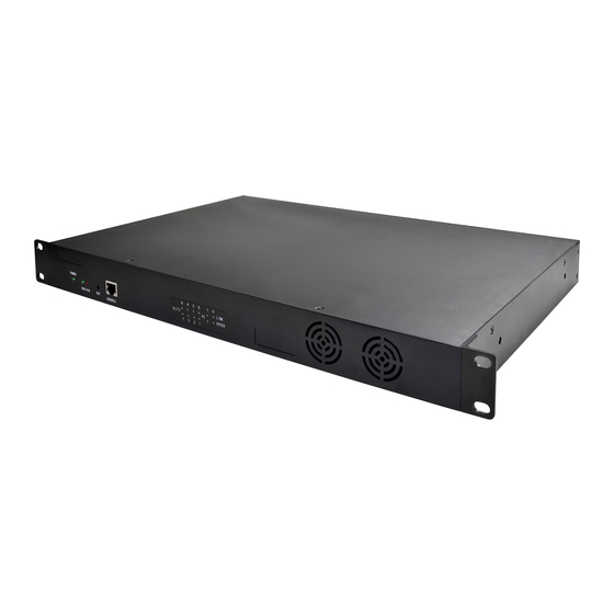
Page 7: Front View
MTG1000 User Manual 1.2.2 Front View Figure 1-2-2 MTG1000 Front View Table 1-2-2 MTG1000 Front View Description Function Color Work Status Off:Power is off POWER Power status indicator Green On: Power is on Slow blinking: Unregister Register indicator Green Fast blinking: Register... -
Page 8: Rj-48C Line Sequence
MTG1000 User Manual 1.2.3 RJ-48c Line sequence MTG1000 trunk gateway adopts standard RJ-48C interface and impedance value is 120Ω. Connected end device by cross lines sequence. 1.3 Functions and Features Protocol standard supported 1.3.1 ● Standard SIP /SIP-T/H.323/PRI/SS7 protocol ● NAT Traversing (STUN) ●... -
Page 9: Industrial Standards Supported
MTG1000 User Manual Industrial standards supported 1.3.3 ● Stationary use environment: EN 300 019: Class 3.1 ● Storage environment: EN 300 019: Class 1.2 ● Transportation environment: EN 300 019: Class 2.3 ● Acoustic noise: EN 300 753 ● CE EMC directive 2004/108/EC ●... -
Page 10: Parameter Setting
MTG1000 User Manual 2. Parameter Setting 2.1 Login First, device FE0 port connect PC with string, and then fill FE0 IP address in browser, FE0 default IP address is 192.168.1.111. It will request customer to input user name and password. Default user name and password are “admin”. -
Page 11: Web Interface Structure And Navigation Tree
MTG1000 User Manual Users through to traverse the left navigation tree, and can complete view, edit and configuration device in the right configuration interface. Figure 2-1-3 Description of System Information 2.2 Web interface structure and navigation tree After entering configuration page, according to demand choose Chinese interface or English interface, the default is English interface. - Page 12 MTG1000 User Manual Figure 2-2-2 Navigation tree MTG configuration flow chart below: 8 / 55...
-
Page 13: Status & Statistics
MTG1000 User Manual 2.3 Status & Statistics Open the operation of the navigation tree information node, and can view the device information and state system. Figure 2-3-1 Status & Statistics 9 / 55... -
Page 14: System Information
Time elapsed from device power on to now Traffic Statics Total bytes of message received and sent by FE0 port Equipment Type Equipment type; this equipment is: MTG1000 Hardware Version Hardware version of device DSP Version Digital signal processing chip driver version... -
Page 15: E1/T1 Status
MTG1000 User Manual 2.3.2 E1/T1 Status Figure 2-3-2 E1/T1 Status Table 2-3-2 Description of E1/T1 status 1. LOS Alarm: Signal loss alarm, this alarm is created when receiving is lost; please check the physical connection whether disconnected. 2. RAI Alarm: Receive remote alarm indication, it is a signal transmitted in the outgoing direction when a terminal determines that it has lost the incoming signal. -
Page 16: Pstn Trunk Status
MTG1000 User Manual Remote blocked, means that communication can only be initiated from remote 9.B-blocked: Both Sides blocked, means that the two sides cannot communication 2.3.3 PSTN Trunk Status Figure 2-3-3 PSTN Trunk Status PSTN trunk status description: 1)PRI Link Status PRI Trunk No. -
Page 17: Pri Call Statistics
MTG1000 User Manual Trunk Mode Peer and Access two modes Register Status Indicate the status of SIP trunk(access mode), register or unregister, when is under peer to peer mode, the values is meaningless, as '---' Link Status Established and Fault status. -
Page 18: Ss7 Trunk Call Statistics
MTG1000 User Manual 2.3.6 SS7 Trunk Call Statistics Figure 2-3-6 SS7 Trunk Call Statistics The parameters of SS7 trunk call statistics are the same with PRI parameters. Please refer to PRI trunk call statistics. 2.3.7 SIP Call Statistics Figure 2-3-7 SIP Trunk Call Statistics... -
Page 19: Network
MTG1000 User Manual Figure 2-3-8 H.323 Trunk Call Statistics H. 323 call statistical parameters and SIP call statistical parameters is same, can be reference SIP parameters statistics show. 2.4 Network Figure 2-4-1 Network Configuration Network Configuration IP address Set FE0 port static IP address. -
Page 20: Pri Config
MTG1000 User Manual 2.5 PRI Config PRI configuration includes PRI parameter and PRI trunk configuration Figure 2-5-1 PRI Config 2.5.1 PRI Parameter Figure 2-5-2 PRI Parameter PRI parameter description Provide six plans: Unknown, ISDN/Telephony numbering plan, data numbering plan, Calling Party telegraph numbering plan, national standard numbering plan, private numbering plan. -
Page 21: Pri Trunk
MTG1000 User Manual Six optional types are provided for called party: Unknown, International number, Called Party Number National number, Network special number, User number, Short code dialing. The Type default option is Unknown. Information Transfer Support speech and 3.1khz audio. The default option is speech. -
Page 22: Ss7 Config
MTG1000 User Manual Indicate PRI network property of E1/T1, it is divided into: “User side” and“Network side”. Switch Side When PRI loopback is carried out, the network properties of E1/T1 port at both receiving and sending sides must be different. - Page 23 MTG1000 User Manual SS7 is a standard protocol to initiate a calling connection with SPC exchange. Notes: 1. “Trunk No.” is a shared data, therefore, SS7 „Trunk No.‟ can't be the same as PRI “Trunk No.” 2. SPC length is 24bits when option “ANSI” or “ITU-CHINA” is selected in item “Standard Type”.
-
Page 24: Ss7 Mtp Link
MTG1000 User Manual 3. SPC length performance on the OPC/DPC structure; SPC pattern instructions of the different structure OPC/DPC input formats. 4. When the SPC length is 24 bits, and chosen ITU, OPC/DPC structure format is :x-y-z; x、y、z is a number of 0-255, such as: 22-222-77 5. -
Page 25: Ss7 Circuit
MTG1000 User Manual SS7 MTP link description Trunk No It is consistent with foregoing “Trunk No” of SS7 trunk. Equipment maximum support 2 signaling links, these two links share workload, when Link No one link fails, the other link will take over the load until restore from failure, and then they will share the load again. -
Page 26: Ss7 Circuit Maintain
MTG1000 User Manual Start CIC No An initial circuit number to this E1/T1 matches by both parties Count A total of 32 channels 2.6.4 SS7 Circuit Maintain According to the different operating modes, 7 circuit maintenance objects into two categories: ports and channel. -
Page 27: Slave Tg Management
MTG1000 User Manual Figure 2-6-8 SS7 Circuit Maintain-Channel If user wants to manage the channel, please select operation mode to channel. Select current port, use will see port status and protocol type. The following will show the slot and channel status. There are 16 kinds of channel states and each state corresponds to a color 2.6.5 Slave TG Management... -
Page 28: Pstn Group Config
MTG1000 User Manual 2.7 PSTN Group Config 2.7.1 E1/T1 Parameter Clock source of E1/T1can be selected “Remote” or “Local”. If selecting E1/T1 port to port0, when user modified port0, port0-3 will be changed together with port0. Port4-7 changed following the port4. -
Page 29: Coder Group
MTG1000 User Manual 2.7.2 Coder Group Figure 2-7-2 Coder Group Coder group description ID standard for Voice ability, total with 8 groups, where 0 is the default group ID Coder Group ID number, the codec that equipment supports in the grouping will be displayed in 0 group. - Page 30 MTG1000 User Manual Dial plan used for configuring the receiving number, user can configure different prefix number, these rules can be divided into 5 groups with a dial plan ID, where 0 is the default setting. Notes: 1. In order to ensure each rule can take effect, long matching numbers (prefix) rule dial plan index value need smaller.
-
Page 31: Dial Timeout
MTG1000 User Manual be set to the same value to accelerate connection rate. 4. Prefix configuration, compatible “digit map” mode. 2.7.4 Dial Timeout Figure 2-7-5 Dial Timeout Figure 2-7-6 Dial Timeout Add Dial timeout description Dial Time ID The number to identify a dial timeout rule... -
Page 32: Pstn Group
MTG1000 User Manual Figure 2-7-7 PSTN Profile PSTN profile is used to configure PSTN call number rules and parameter. Figure 2-7-8 PSTN Profile Add PSTN profile add description PSTN Profile ID The number to the PSTN Profile Description Description of the PSTN Profile Code Group ID Refer to "Coder Group"... -
Page 33: Pstn Group Management
MTG1000 User Manual Figure 2-7-10 PSTN Group Add Adding PSTN group needs to fill three parameters: trunk group Numbers, trunk group Name. Channel selection mode and at most, can add up to 16 set of data. Channel selection mode refers to E1/T1 timeslot allocation strategy in a trunk group. -
Page 34: Sip Config
MTG1000 User Manual When cross E1 port operation, don’t choose start/termination of the time. 2.8 SIP Config 2.8.1 SIP Parameter Figure 2-8-1 SIP Parameter The default Local SIP Port is 5060, and Local Domain set here can replace SIP account. -
Page 35: Sip Account
MTG1000 User Manual SIP trunk description Trunk No The range of number is 1~99 Trunk Name Description the trunk Remote Address IP address of remote platform interfacing with this equipment. Q.931 port of SIP of remote platform interfacing with this equipment, the default is... - Page 36 MTG1000 User Manual Figure 2-8-5 SIP Account Add This option is when the equipment is in the registered mode, used to manage SIP trunk account. SIP trunk account SIP Account ID SIP Account Number, from 0-127 Description Description of the SIP account IP trunk group number, “any”...
-
Page 37: H323 Config
MTG1000 User Manual 2.9 H323 Config 2.9.1 H.323 Parameter Figure 2-9-1 H.323 Parameter H.323 Parameter description Call Mode Supports faststart mode and conventional mode, faststart mode through faster. Call Signal Port Default call signal port is 1720 Enable H245 Tunneling H. -
Page 38: Trunk
MTG1000 User Manual 2.9.2 H.323 Trunk Figure 2-9-2 H.323 Trunk Figure 2-9-3 H.323 Trunk Add H.323 trunk description Trunk No. Can add up to 63 trunk Trunk Name Named for the trunk Remote IP Equipment to end interface platform IP Remote Port Equipment to end interface platform port, default is 1720. -
Page 39: Ip Group Config
MTG1000 User Manual 2.10 IP Group Config The user can group manage SIP/H.323 trunk through IP packet configuration. 2.10.1 IP Profile Figure 2-10-1 IP Profile Figure 2-10-2 IP Profile Add IP profile add IP Profile ID IP property identification number can be configured to 15 properties... -
Page 40: Ip Group
MTG1000 User Manual 2.10.2 IP Group Figure 2-10-3 IP Group Figure 2-10-4 IP Group Add Add the IP group including the IP group ID, IP group name, IP trunk selection. User can add a total of 16 IP group. IP routing mod is to show in an IP group SIP time distribution strategy. There are four options: Ascending, Descending, Cyclic ascending, Cyclic descending. -
Page 41: Call Routing
MTG1000 User Manual 2.11 Call Routing 2.11.1 Routing Parameter Figure 2-11-1 Routing Parameter Inbound and outbound call routing configuration The key steps how to Configure routing: The more accurate routing configuration, index values should be smaller. “Any” and "." are useful; suggesting configuration, to avoid cannot match the routing. -
Page 42: Pstn->Pstn Routing
MTG1000 User Manual Figure 2-11-3 PSTN->IP Add “PSTN -> IP Routing”: Routing Call from PSTN to IP PSTN->IP routing description Index Routing index number (0 ~ 255) , “PSTN->IP Routing” priority rule is according to the index to set. Reference dial plan. -
Page 43: Ip->Pstn Routing
MTG1000 User Manual Figure 2-11-5 PSTN->PSTN Add “PSTN->PSTN Routing”:Routing Call from PSTN to PSTN PSTN->PSTN Routing Index Routing index number (0 ~ 255) , “PSTN->IP Routing” priority rule is according to the index to set. Reference dial plan. Description Describe the routing Source Type Source type is PSTN group or PRI/SS7 trunk. -
Page 44: Ip->Ip Routing
MTG1000 User Manual Figure 2-11-7 IP->PSTN Routing “IP -> PSTN Routing”: Routing Call from IP to PSTN IP->PSTN routing configuration and PSTN->PSTN routing configuration are similar, the only difference is PSTN destination group. 2.11.5 IP->IP Routing Figure 2-11-8 IP->IP Routing Figure 2-11-9 IP->IP Add... -
Page 45: Number Manipulation
MTG1000 User Manual IP->IP routing configuration and PSTN->IP configuration are similar. The only difference is that the destination is the IP group. 2.12 Number Manipulation Select “Number Manipulation” in navigation tree, the display interface is shown as below: Figure 2-12-1 Number Manipulation "Number Manipulation”... -
Page 46: Pstn->Ip Callee
MTG1000 User Manual 2.12.1 PSTN->IP Callee Figure 2-12-2 PSTN->IP Callee Figure 2-12-3 PSTN->IP Callee Add “PSTN->IP Callee”:Replace the called number from PSTN PSTN->IP destination number Index Index number (0 ~ 127) Description Describe the transformation of the number PSTN Group Refer to “PSTN Group”, “any”... -
Page 47: Pstn->Ip Caller
MTG1000 User Manual 2.12.2 PSTN->IP Caller Figure 2-12-4 PSTN->IP Caller Figure 2-12-5 PSTN->IP Caller Add PSTN->IP Callee configuration parameters and IP->PSTN Caller configuration parameters are the same. Figure 2-12-6 PSTN->PSTN Callee PSTN->PSTN Callee configuration parameters with the above is basically same, only more of a “number type”... - Page 48 MTG1000 User Manual Figure 2-12-7 PSTN->PSTN Caller "Presentation indicator" parameter used to indicate the status of the operation. The operation of the option the right are: Not configured, Allowed, Restricted. Figure 2-12-8 IP->PSTN Callee IP->PSTN callee description Index Index number (0 ~ 127)
-
Page 49: Voice & Fax
MTG1000 User Manual Figure 2-12-10 IP->IP Callee Figure 2-12-11 IP->IP Caller 2.13 Voice & Fax Figure 2-13-1 Voice & Fax 45 / 55... - Page 50 MTG1000 User Manual Voice & Fax description Disconnect Call when no RTP When selected “Yes”, detected call’s silence time packet longer than silence timeout that for a long time not received RTP packets, then hangup the call. Voice Parameter Period without RTP packet...
-
Page 51: Management Parameter
MTG1000 User Manual 2.14 Management Parameter Figure 2-14-1 Management Parameter Management parameter description WEB Port Listening port of local WEB service, the default is 80. Telnet Port Listening port of local Telnet service, the default is 23. Syslog Enable The default is “No”. -
Page 52: Snmp Parameter
MTG1000 User Manual 2.14.2 SNMP Parameter Simple Network Management Protocol (SNMP) is application layer protocol, and used to manage communication line. Figure 2-14-3 SNMP Parameter SNMP Parameter description SNMP Enable Whether enable SNMP function SNMP Manager Address Network management server IP address... -
Page 53: Data Backup
MTG1000 User Manual 2.14.3 Data Backup Figure 2-14-4 Data Backup Database and dial rules will be saved to the local computer system logs through data backup. 2.14.4 Data Restore Figure 2-14-5 Data Restore Data restore description Database Click "Browse" to select the Database file, and then click "Restore". -
Page 54: Firmware Upload
MTG1000 User Manual 2.14.6 Firmware Upload Figure 2-14-7 Firmware Upload Firmware upload description Software Click "Browse" to select the firmware, and then click "Upload". Click "Browse" to select the Web software, and then click "Upload". 2.14.7 Modify Password Figure 2-14-8 Modify Password After entering configuration page, please modify password to ensure the system security. -
Page 55: Faq
1) Connect the CONSOLE with your PC Serial Port. The baud rate is 9600 bps. The user name and password is "admin". When users logged in system, and then run command "show int" for getting the IP. Please refer to http://www.dinstar.com/service/faq_145.aspx 3.2 If meet other questions, please from Dinstar website and download trouble shootingV4.0 http://www.dinstar.com/service/Training.aspx .URL is: 4.
Need help?
Do you have a question about the MTG1000 and is the answer not in the manual?
Questions and answers