Table of Contents
Advertisement
aqua
computer
User and installation manual
User and installation manual
User and installation manual
User and installation manual
All information contained in this manual is subject to change without prior notice.
© 2016
VISION
aquasuite version 2017
Current as of December 2016
All rights reserved.
Aqua Computer GmbH & Co. KG
Gelliehäuser Str. 1, 37130 Gleichen
VISION
ENGLISH: PAGE 1
DEUTSCH: SEITE 23
- 1 -
Advertisement
Table of Contents

Related Manuals for Aqua Computer VISION


Summary of Contents for Aqua Computer VISION
- Page 1 DEUTSCH: SEITE 23 Current as of December 2016 All information contained in this manual is subject to change without prior notice. All rights reserved. © 2016 Aqua Computer GmbH & Co. KG - 1 - Gelliehäuser Str. 1, 37130 Gleichen...
-
Page 2: Table Of Contents
2. Safety precautions.................4 3. Assembly instructions..............4 3.1. VISION Touch (53232, 53235)............4 3.2. VISION table top units (53236, 53237, 53238)......4 3.3. VISION connection terminal for kryographics (23664, 23665, 23666, 23667)..................4 3.4. cuplex kryos NEXT with VISION (21xxx)...........4 4. Electrical connections..............5 4.1. VISION module connector overview..........5 4.2. - Page 3 11.2. aquaremote multi device mode..........16 11.3. User defined infrared commands..........16 11.4. aquaremote: “VISION”, “Computer”, “Media” modes....16 11.5. aquaremote: Special functions in “VISION” mode......17 11.6. aquaremote: Special functions in “Computer” mode.....17 11.7. aquaremote: Special functions in “Media” mode......17 12. LED configuration (devices with integrated RGB LED only)....18 12.1.
-
Page 4: Preface
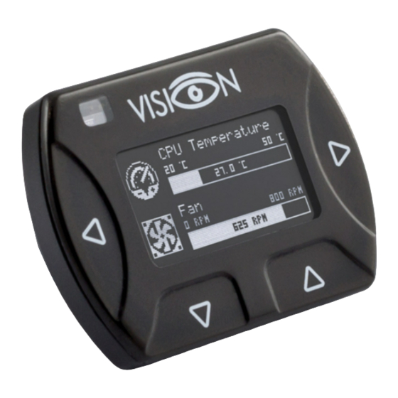
The VISION module is a multi-purpose display and monitoring controller with inte- grated OLED display. As this manual covers all members of the VISION series, some chapters of this manual will not apply to all product versions. Considering the fast technical development, we reserve the right to perform alter- ations to the products at any time. -
Page 6: Connector "Flow/Alarm
Configuration using USB connection Configuration using USB connection Configuration using USB connection The VISION module can be connected to a PC via USB interface and can then be configured using the aquasuite software. Comprehensive visualization and logging - 6 - Aqua Computer GmbH &... -
Page 7: Operation Via Keys And Display (Vision Touch Only)
Operation via keys and display (VISION Touch only) Operation via keys and display (VISION Touch only) Devices of the VISION Touch series are equipped with four keys that can be used to configure the device. Alternatively, individual key functions may be assigned for each display screen. -
Page 8: Symbols In The Headlines
With desktop mode enabled, elements of the overview page may cover program symbols on your desktop, but mouse clicks are transmitted to underlying desktop symbols. - 8 - Aqua Computer GmbH & Co. KG © 2016 Gelliehäuser Str. 1, 37130 Gleichen... -
Page 9: Creating New Overview Pages And Activating Edit Mode
If you want to move an element, “drag” this element while holding down the mouse button. Release the mouse button when the element is at the desired po- sition. © 2016 Aqua Computer GmbH & Co. KG - 9 - Gelliehäuser Str. 1, 37130 Gleichen... -
Page 10: Settings Of Individual Values
Please refer to the next chapter for details. Once a - 10 - Aqua Computer GmbH & Co. KG © 2016 Gelliehäuser Str. 1, 37130 Gleichen... -
Page 11: Export And Import Of Overview
Data log (aquasuite) Data log (aquasuite) Data log (aquasuite) Data from all connected Aqua Computer devices can be logged by the aquasuite. Logged data can then be analyzed by creating charts or be exported to files. 8.1. 8.1. Log settings Log settings 8.1. -
Page 12: Manual Data Export
Saved data can be exported from the data log into a XML file. To do so, select “Analyze data” below the “Data log” headline in the listing. Select the “Data - 12 - Aqua Computer GmbH & Co. KG © 2016 Gelliehäuser Str. 1, 37130 Gleichen... -
Page 13: Automatic Data Export
Hardware flow sensor Hardware flow sensor The second sensor in the list represents the flow sensor input of the VISION mod- ule. Calibration values for sensors sold by Aqua Computer can conveniently be se- lected from a drop-down list. Select the appropriate entry for the flow sensor con- nected to the VISION module. -
Page 14: Software Sensors (Configuration Using Aquasuite Only)
The last sixteen sensors in the list are software sensors and can be used to transmit sensor data that is not physically available to the VISION module from the com- puter by USB connection or from an aquaero 5/6 by aquabus connection. -
Page 15: Display Configuration
USB keyboard command to wake up the PC when a key of the VISION module is pressed. To do so, assign “User defined 12” to the key, click the “Edit” button and select “Power (system)” for this key. In a similar fashion, you could use the up and down keys to adjust PC volume when the media player screen is displayed. -
Page 16: Infrared Configuration (Devices With Ir Receiver Only)
The multi device mode can be used to control up to ten VISION modules indepen- dently using an aquaremote. Configure a unique key for each VISION module. In order to control a specific VISION module with activated multi device mode, press the desired mode key ( , or TV) followed by the configured unique key. -
Page 17: Aquaremote: Special Functions In "Vision" Mode
VISION Three keys of the aquaremote select the mode of op- eration: “VISION” mode is selected by pressing the “ ” key, the “ ” key selects “Computer” mode and “Media” mode can be selected by pressing the „TV“... -
Page 18: Led Configuration (Devices With Integrated Rgb Led Only)
Timer Timer Timer The VISION module can be used as a countdown timer. Actions may be triggered when the timer is started or runs out. Devices with integrated RGB LED only: The RGB LED can be configured to visual- ize the current timer state. If activated, the LED will be white for the first 50 % of the timer interval, followed by blue for another 25 % and green for the final 25 %. -
Page 19: Alarm Clock (Devices With Integrated Rgb Led Only)
Alarm clock (devices with integrated RGB LED only) Alarm clock (devices with integrated RGB LED only) The VISION module can be used as an optical alarm clock. Time, days, colors and duration can be configured. Please note that the VISION module does not contain a buffered real time clock, so the clock is reset if power supply to the de- vice is interrupted. -
Page 20: Aquabus Configuration
Flow/Alarm header function Flow/Alarm header function The “Flow/Alarm” header of the VISION module can either be used as a flow sen- sor input or as an alarm output: Flow sensor: You may connect a flow sensor to this header using the appro- ●... -
Page 21: Basic Settings (Aquasuite)
VISION sired language in the basic aquasuite settings and restart the aquasuite software. Afterwards, perform a firmware update of the VISION module to change the lan- guage. During the firmware update process, do not disconnect the device from the PC and do not power down the PC! After the firmware is successfully updated, the aquasuite software will be automatically closed. -
Page 22: Waste Disposal
24/7. To get in direct contact with our customer support team, we offer several options: email: support@aqua-computer.de Address: Aqua Computer GmbH & Co. KG Gelliehäuser Str. 1 37130 Gleichen Germany Tel: +49 5508 9749290 (9-16 h Central European Time) Fax: +49 5508 9749291 - 22 - Aqua Computer GmbH &...
Need help?
Do you have a question about the VISION and is the answer not in the manual?
Questions and answers