Table of Contents
Advertisement
Quick Links
aqua
computer
User and installation manual
User and installation manual
User and installation manual
User and installation manual
The information contained in this manual is subject to change without prior
© 2014
aquaero 5
aquaero 6
notice. All rights reserved.
Current as of April 2014
Aqua Computer GmbH & Co. KG
Gelliehäuser Str. 1, 37130 Gleichen
AQUAERO 5/6
ENGLISH: PAGE 1
DEUTSCH: SEITE 49
- 1 -
Advertisement
Table of Contents

Related Manuals for Aqua Computer aquaero 5


Summary of Contents for Aqua Computer aquaero 5
- Page 1 The information contained in this manual is subject to change without prior notice. All rights reserved. Current as of April 2014 ENGLISH: PAGE 1 DEUTSCH: SEITE 49 © 2014 Aqua Computer GmbH & Co. KG - 1 - Gelliehäuser Str. 1, 37130 Gleichen...
-
Page 2: Table Of Contents
5.1. Operation via USB connection.............13 5.2. Operation without USB connection............14 5.3. Operation via keys and display (aquaero 5/6 PRO and XT only)....14 5.4. Operation via aquaremote (aquaero 5/6 PRO and XT only)....14 5.5. Configuration menu (aquaero 5/6 PRO and XT only)......15 6. - Page 3 14.2. Power outputs...................34 14.3. Switching outputs and relays...............34 15. Pump configuration (aquasuite/device menu)........34 15.1. aquastream XT..................35 15.2. D5 pumps connected via aquabus............35 16. User interface configuration (aquasuite/device menu, aquaero 5/6 XT/PRO only)..................35 16.1. Language setting................35 16.2. Display settings.................36 © 2014 Aqua Computer GmbH &...
- Page 4 AQUAERO 5/6 16.3. Key settings..................36 16.4. Programmable function keys (device menu of aquaero 5/6 XT only)..36 17. Information page configuration (aquasuite/device menu, aquaero 5/6 XT/PRO only)..................36 17.1. Screenshot function (aquasuite only)............37 17.2. Special pages and logo (aquasuite only)..........37 17.3.
-
Page 5: Aquaero
26.7. Expansion board connected to aquabus is not discovered......47 27. Technical details and care instructions..........48 27.1. Technical details................48 27.2. Care instructions................48 27.3. Waste disposal.................48 27.4. Contact Aqua Computer..............48 © 2014 Aqua Computer GmbH & Co. KG - 5 - Gelliehäuser Str. 1, 37130 Gleichen... -
Page 6: Scope Of Delivery
4x Temperature sensor 70 cm 1x Internal USB connection cable (5 pins), length ca. 100 cm 1x aquabus / speed signal cable Mounting material aquaero 5 XT and aquaero 6 XT only: 1x aquaremote infrared remote control 2. Preface 2. Preface 2. -
Page 7: Electrical Connectors
Aqua Computer GmbH & Co. KG cus ed to result in personal injury. Aqua Computer GmbH & Co. KG cus- - - - ed to result in personal injury. Aqua Computer GmbH & Co. KG cus ed to result in personal injury. -
Page 8: Connector "Power
PWM controlled fans. For PWM fans, select “Outputs” “Fans” “Fan → → 4” from the menu and set “Control mode” to “PWM controlled”. - 8 - Aqua Computer GmbH & Co. KG © 2014 Gelliehäuser Str. 1, 37130 Gleichen... -
Page 9: Connector "Pwm 1/2
→ “Flow 2” from the menu and set “Mode” to “Fan 1 = Flow sensor”. Pin assignment: Pin 1: GND Pin 2: 0-12 V Pin 3: Speed signal Pin 4: PWM signal (aquaero 5: Fan 4 only) 4.4. Connector “PWM 1/2” 4.4. Connector “PWM 1/2” 4.4. Connector “PWM 1/2”... -
Page 10: Connector "Aquabus Low Speed/High Speed
4.6. Connector “aquabus low speed/high speed” 4.6. Connector “aquabus low speed/high speed” Connectors for communication with other devices from Aqua Computer. The aquaero 5/6 features one „low speed“ (aquabus 1) and one „high speed“ (aquabus 2) port. Products compatible to the “low speed” port: multiswitch USB ●... -
Page 11: Connector „Sensors
Pin assignment: Pin 1: VCC LED 1 Pin 2: VCC LED 2 Pin 3: GND © 2014 Aqua Computer GmbH & Co. KG - 11 - Gelliehäuser Str. 1, 37130 Gleichen... -
Page 12: Connector „Relay
Connector for additional power supply from the 5 Volts standby power line of the power supply unit. If connected to standby power, the aquaero 5 will re- main functional while the computer is in soft off state even if no USB standby power is supplied. -
Page 13: Operation Of The Aquaero 5/6 Device
5.1. Operation via USB connection 5.1. Operation via USB connection The aquaero 5/6 can be connected to a PC via USB interface and can then be configured using the aquasuite software. Comprehensive visualization and logging options are also available in the aquasuite software. The aquasuite software can be used with any aquaero 5/6 variant (XT, PRO and LT). -
Page 14: Operation Without Usb Connection
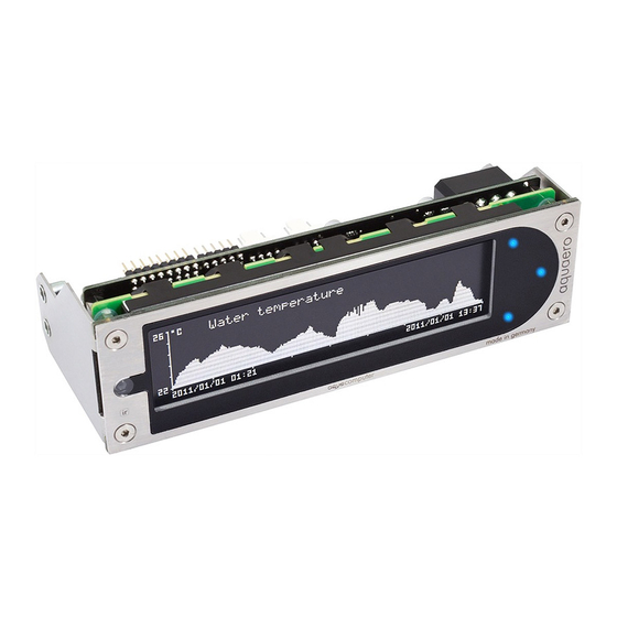
5.3. Operation via keys and display (aquaero 5/6 PRO and XT only) 5.3. Operation via keys and display (aquaero 5/6 PRO and XT only) Both aquaero 5/6 PRO and aquaero 5/6 XT are equipped with a LC display and keys and can be fully configured using these. Both variants provide three keys to the right of the display, the aquaero 5/6 XT additionally provides four programmable keys below the display. -
Page 15: Configuration Menu (Aquaero 5/6 Pro And Xt Only)
The infrared remote control aquaremote can be used with any aquaero 5/6 XT or aquaero 5/6 PRO device. The infrared receiver is located left of the display of the aquaero. The aquaero 5 LT is not equipped with an infrared receiver and can therefore not be controlled by aquaremote. -
Page 16: Special Functions In "Aquaero" Mode
(„T“ first page, „Y“ second page, ...). In the configuration menu, the keyboard can be used to enter the characters and numbers printed on the keys. - 16 - Aqua Computer GmbH & Co. KG © 2014 Gelliehäuser Str. 1, 37130 Gleichen... -
Page 17: Special Functions In "Pc Keyboard" Mode
7. Operation concept: Sensor, controller, output 7. Operation concept: Sensor, controller, output 7. Operation concept: Sensor, controller, output The aquaero 5/6 uses an extremely flexible concept for linking sensors to the various outputs. The device automatically determines which sensors ensors... -
Page 18: Controllers
● party software. They can for example be used to transmit the current CPU temperature to the aquaero 5/6 and use this value for controlling fan speeds. Up to eight software sensors can be configured. Flow sensors (Control processes can not be based on flow sensor val- ●... -
Page 19: Aquasuite Software
The software is not required for oper- ation though. All configuration parameters can be saved into the device's memory, the aquaero 5/6 XT and aquaero 5/6 PRO variants can also be configured using the keys an the device only. -
Page 20: Overview Pages (Aquasuite)
If a overview page is unlocked for editing while desktop mode is active, the page will be displayed in the aquasuite window for editing and the current desktop will be displayed as background for your convenience. - 20 - Aqua Computer GmbH & Co. KG © 2014 Gelliehäuser Str. 1, 37130 Gleichen... -
Page 21: Creating New Overview Pages And Activating Edit Mode
“drag” this element while holding down the mouse button. Release the mouse button when the element is at the desired position. © 2014 Aqua Computer GmbH & Co. KG - 21 - Gelliehäuser Str. 1, 37130 Gleichen... -
Page 22: Settings Of Individual Values
The picture will be displayed on the overview page. More complex controls such as data bindings and animations are also avail- able but will require some programming experience for configuration. - 22 - Aqua Computer GmbH & Co. KG © 2014 Gelliehäuser Str. 1, 37130 Gleichen... -
Page 23: Log Data Chart
10. Data log (aquasuite) 10. Data log (aquasuite) 10. Data log (aquasuite) Data from all connected Aqua Computer devices can be logged by the aquasuite. Logged data can then be analyzed by creating charts or be ex- ported to files. -
Page 24: Log Settings
Mouse movement while right button is pressed will move the displayed ● area of the diagram. - 24 - Aqua Computer GmbH & Co. KG © 2014 Gelliehäuser Str. 1, 37130 Gleichen... -
Page 25: Manual Data Export
“Data sources” tab in the chart configuration and select a data set to be ex- ported. If no data sources are available, you will have to configure the log © 2014 Aqua Computer GmbH & Co. KG - 25 - Gelliehäuser Str. 1, 37130 Gleichen... -
Page 26: Automatic Data Export
Mode and up to three data sources (temperature sensors) can be selected for each of the four virtual temperature sensors. The selected mode determines, how the virtual temperature is calculated from the data sources: - 26 - Aqua Computer GmbH & Co. KG © 2014 Gelliehäuser Str. 1, 37130 Gleichen... -
Page 27: Software Temperature Sensors
USB connection. This requires the third party software to be installed, configured and running as well as the “Aqua Computer Service” to be installed and active. 2. A third party software directly transmits data to the aquaero via USB connection. -
Page 28: Flow Sensors
In the AIDA64 preferences menu, writing to WMI must be activated in the „external applications“ sub-menu: After activating “Use sensor with Aqua Computer Service” in the aquasuite, click the “Select data source” button to assign the currently selected software sensor to a temperature sensor provided by third party software. -
Page 29: Power Measurement
AQUAERO 5/6 Aqua Computer can conveniently be selected from a drop-down list, a user defined value can be set for other flow sensor types. Flow sensors models mps flow 100/200/400 and “high flow USB” have to be configured using a direct USB connection to the PC before they can be uses as aquabus expansion devices with an aquaero. -
Page 30: Pressure Sensors
In the graphical curve display, the currently displayed area can be changed using the following methods: - 30 - Aqua Computer GmbH & Co. KG © 2014 Gelliehäuser Str. 1, 37130 Gleichen... -
Page 31: Set Point Controllers
Temperature and output values can be set. One RGB LED con- troller is available. © 2014 Aqua Computer GmbH & Co. KG - 31 - Gelliehäuser Str. 1, 37130 Gleichen... -
Page 32: Fan Configuration (Aquasuite/Device Menu)
If activated, the aquaero unit will set the output to the configured start boost power for the configured duration before switching to - 32 - Aqua Computer GmbH & Co. KG © 2014 Gelliehäuser Str. 1, 37130 Gleichen... -
Page 33: Programmable Fuses
14.1. LED outputs For each LED output, output behavior during alarm condition can be set: Normal operation: The output is not affected by alarm conditions. ● © 2014 Aqua Computer GmbH & Co. KG - 33 - Gelliehäuser Str. 1, 37130 Gleichen... -
Page 34: Power Outputs
14.2. Power outputs 14.2. Power outputs For both power outputs of the aquaero 5/6, a name can be set and the out- put range can be limited in both directions (“Minimum power”/”Maximum power”). The check box “Hold minimum power” determines fan output be- havior while the assigned controller output value is below the minimum pow- er setting: If the box is not checked, the fan output will switched off. -
Page 35: Aquastream Xt
16.1. Language setting In order to change the language for information pages and menus of the aquaero 5/6, simply press the middle side key of the aquaero 5/6 (or the OK button of the aquaremote if available) four times four times... -
Page 36: Display Settings
Key sound volume of the aquaero 5/6 XT/PRO keys can be adjusted, the keys can also be disabled to prevent user interaction. Touch key sensitivity can be adjusted for each of the seven aquaero 5/6 XT keys as well as brightness of the key illumination. If one or more of the touch keys constantly report to be pressed due to excessive sensitivity settings, the touch panel will be temporarily disabled. -
Page 37: Screenshot Function (Aquasuite Only)
The information page “USB LCD page” can be used to transfer user defined content onto the aquaero display. Currently, the third party software „LCD- Hype“ (author Daniel Frömmel, freeware, lcdhype.condense.de) is supported. © 2014 Aqua Computer GmbH & Co. KG - 37 - Gelliehäuser Str. 1, 37130 Gleichen... -
Page 38: Alarm Actions (Aquasuite/Device Menu)
18. Alarm actions (aquasuite/device menu) 18. Alarm actions (aquasuite/device menu) The aquaero 5/6 features eight alarm levels, which van be configured indi- vidually. Up to three actions can be configured for each alarm level. For alarm actions, speed signal output, alarm buzzer, relay, profile selection and USB keyboard commands are available. -
Page 39: Alarm Configuration (Aquasuite/Device Menu)
20. Timer configuration (aquasuite/device menu) 20. Timer configuration (aquasuite/device menu) The aquaero 5/6 features a clock timer to perform various actions on prede- fined times and days of the week. For timer actions, speed signal output, alarm buzzer, relay, profile selection and USB keyboard commands are avail- able. -
Page 40: Configure Timer Events
By default configuration, powering the PC up or down by remote control is deactivated for safety reasons. The aquaremote has a red power button that can be used for this function, the aquaero 5/6 can be trained to accept the corresponding infrared command. Select the actions to be performed to - 40 - Aqua Computer GmbH &... -
Page 41: Data Log (Aquasuite/Device Menu)
22. Data log (aquasuite/device menu) 22. Data log (aquasuite/device menu) The aquaero 5/6 unit can be configured to record measured values over an extended period of time. The menu “Log data” can be used to configure up to 16 measured values to be recorded at adjustable time intervals. The recorded information can then be displayed as charts on the aquaero display itself (menu “User interface”... -
Page 42: Save Log Data As Xml (Aquasuite Only)
Events can be filtered by type in the aquasuite event listing for better clarity. In the aquaero 5/6 XT/PRO device menu, the event log can be ac- cessed by selecting the corresponding symbol. Newly added events/alarms will be marked by a plus symbol in the event list, events/alarms no longer in effect will be marked by a minus symbol. -
Page 43: Firmware Update And Factory Defaults (Aquasuite Only)
23.5. aquaero 5 LT expansion device firmware 23.5. aquaero 5 LT expansion device firmware As a special feature, aquaero 5 LT devices can be programmed with an ex- pansion device firmware to be controlled as an aquabus expansion board by another aquaero 5 or aquaero 6 device. -
Page 44: Basic Settings (Aquasuite)
The service (background service) synchronizes date and time of all aquaero 5/6 devices connected to the PC and provides software sensors to the aquaero. - 44 - Aqua Computer GmbH & Co. KG © 2014 Gelliehäuser Str. 1, 37130 Gleichen... -
Page 45: Functional Upgrades By Aquabus Devices
Date/time 1 (111) multiswitch (53050, 53051) 8x power output 8x LED output (20-21) 1x Relay output Overlapping bus addresses, only on device per address! © 2014 Aqua Computer GmbH & Co. KG - 45 - Gelliehäuser Str. 1, 37130 Gleichen... -
Page 46: Trouble Shooting
LT programmed as expansion device Delete and reprogram device firmware Corrupt firmware Delete and reprogram device firmware Hardware failure Contact Aqua Computer Support - 46 - Aqua Computer GmbH & Co. KG © 2014 Gelliehäuser Str. 1, 37130 Gleichen... -
Page 47: Aqua Computer Gmbh & Co. Kg
Incorrect key sensitivity setting (XT only) Adjust key sensitivity (aquasuite/aquaremote) Defective touch controller board (XT only) Contact Aqua Computer or replace with spare part no. 53128. 26.6. Device does not respond to aquaremote 26.6. Device does not respond to aquaremote 26.6. -
Page 48: Technical Details And Care Instructions
27.1. Technical details 27.1. Technical details 27.1. Technical details Dimensions W x H x D: 148 mm x 43 mm x 59 mm (aquaero 5/6 XT/PRO) 144 mm x 42 mm x 22 mm (aquaero 5 LT) Power supply voltage: 12 V DC ±5 %, 5 V DC ±5 %...
Need help?
Do you have a question about the aquaero 5 and is the answer not in the manual?
Questions and answers