TESTO 871 Instruction Manual
Thermal imager
Hide thumbs
Also See for 871:
- Instruction manual (46 pages) ,
- Short instructions (7 pages) ,
- Quick start manual (2 pages)

Related Manuals for TESTO 871


Summary of Contents for TESTO 871
- Page 1 871 - Thermal Imager Instruction manual Short Instruction instructions manual Thermography pocket guide Videos...
-
Page 3: Table Of Contents
Contents Contents 1 Safety and waste disposal ..............5 1.1 Zu diesem Dokument ................5 1.2 Safety ..................... 5 1.3 Waste disposal ..................7 2 Technical data ..................8 2.1 Bluetooth module ................... 8 2.2 General technical data ................8 3 Description of the instrument ............. - Page 4 Contents 7.7 Image type ................... 35 7.8 Activating humidity, solar or electrical mode ........35 7.9 Activating the differential temperature ..........36 7.10 Configuration ..................37 7.10.1 Settings ................. 37 7.10.2 SuperResolution ..............38 7.10.3 Save JPEG function .............. 38 7.10.4 Connectivity ................
-
Page 5: Safety And Waste Disposal
Only perform maintenance and repair work on this instrument that is described in this documentation. Follow the prescribed steps exactly. • Use only original spare parts from Testo. • During operation, this instrument must not be pointed at the sun or other intensive sources of radiation (e.g. - Page 6 1 Safety and waste disposal Batteries • Improper use of batteries may cause the batteries to be destroyed, or lead to injury due to current surges, fire or escaping chemicals. • Only use the batteries supplied in accordance with the instructions in the instruction manual.
-
Page 7: Waste Disposal
• At the end of its useful life, dispose of the instrument via separate collection for electrical and electronic devices. Please observe local regulations regarding waste disposal, or alternatively return the product to Testo for disposal. -
Page 8: Technical Data
2 Technical data 2 Technical data 2.1 Bluetooth module The use of the wireless module is subject to the regulations and stipulations of the respective country of use, and the module may only be used in each case in countries for which a country certification has been granted. - Page 9 Coldspot • Hotspot • Differential temperature • ScaleAssist • IFOV warner • Surface moisture distribution • Humidity measurement with testo 605i humidity probe • Solar mode (manual) • Electrical mode (manual) • Electrical measurement with testo 770 wireless clamp meter...
- Page 10 2 Technical data Imager equipment Feature Values Digital camera Fullscreen mode File format .jpg • Video streaming • WiFi via the App Image storage Feature Values • .jpg File format • .bmt • Option of exporting in .bmt .jpg .png .csv .xls Memory capacity...
- Page 11 Protection class (IEC 60529) IP 54 Vibration (IEC 60068-2-6) Standards, tests, warranty Feature Values 2014/30/EU 2014/53/EU Warranty 2 years, warranty conditions: see www.testo.com/warranty You can find the EU declaration of conformity on the Testo homepage www.testo.com under the product-specific downloads.
-
Page 12: Description Of The Instrument
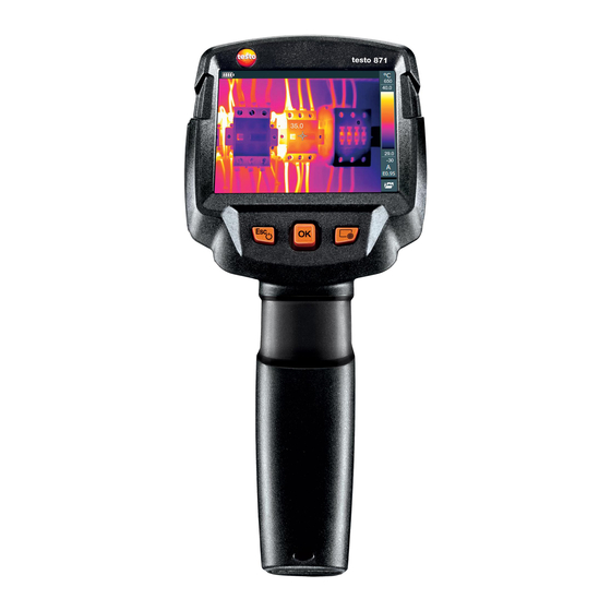
3 Description of the instrument 3 Description of the instrument 3.1 Use The testo 871 is a handy, robust thermal imager. You can use it to undertake the non-contact measurement and display of surface temperature distribution. Areas of application •... -
Page 13: Displays Overview
6 Infrared camera lens; Takes infrared images; protects the lens protective cap 7 Digital camera Takes real images (testo 871-2 only) Trigger Saves the displayed image 9 Battery compartment Contains the rechargeable battery 3.3 Displays overview Element... -
Page 14: Power Supply
3 Description of the instrument Element Function Battery capacity / charge status: : Battery operation, capacity 75-100% : Battery operation, capacity 50-75% : Battery operation, capacity 25-50% : Battery operation, capacity 10-25% : Battery operation, capacity 0-10% : Mains operation, battery is charging 3 Image display IR image or real image display 4 °C or °F... -
Page 15: Operation
4 Operation 4 Operation 4.1 Initial operation Please read the testo 871 1st steps commissioning instructions supplied (0970 8652). 4.2 Switching instrument on and off Switching on the camera - Remove protective cap from the lens. - Press The camera starts. -
Page 16: Getting To Know The Menu
4 Operation Switching off the camera - Press and hold down until the progress bar is complete. The display goes off. The camera is switched off. 4.3 Getting to know the menu - Press to open the menu. - Move the joystick down/up to... -
Page 17: Quick Select Button
4 Operation 4.4 Quick select button The quick select button is another navigation option that you can use to call up certain functions simply at the touch of a button. Quick select menu items Menu item Function Image gallery Opens an overview of saved images. Set scale limits. - Page 18 4 Operation - Move the joystick up/down until the orange box appears around the required menu item. - Press The quick select button is assigned to the selected menu item. The icon for the selected function is displayed bottom right. Using the quick select button - Press ...
-
Page 19: Wlan Connection - Using The App
5 WLAN connection - using the App 5.1 Activating/disabling the connection To connect via WLAN, you need a tablet or smartphone with the Testo Thermography App already installed on it. You can get the App from the App Store for iOS devices or from the Play Store for Android devices. -
Page 20: Using The App
5 WLAN connection - using the App 5.2 Using the App 5.2.1 Establishing a connection - WLAN is activated in the thermal imager. - Smartphone/tablet -> Settings -> WLAN settings -> camera is shown with serial number and can be selected. - Press Connect. - Page 21 5 WLAN connection - using the App Gallery - The thermal imager is connected via WLAN. Selection -> Gallery The saved images are displayed and can be managed.
-
Page 22: Bluetooth Connection
6 Bluetooth® connection ® 6 Bluetooth connection A connection between the thermal imager and the testo 605i humidity probe or ® testo 770-3 clamp meter can be established via Bluetooth ® Bluetooth 4.0 required - Open Menu. - Move the joystick down and select Configuration. - Page 23 6 Bluetooth® connection When connected to the humidity probe The thermal imager switches automatically to humidity measurement. Humidity probe readings are displayed in the header. If a WLAN connection is enabled in addition, the Bluetooth data transfer is continued. However, it is not possible to establish a new connection to a humidity probe.
-
Page 24: Performing The Measurement
7 Performing the measurement 7 Performing the measurement Factory settings The instrument settings can be reset to the factory settings. Time/date, country settings and counter are not reset. Menu -> Configuration -> Reset options. - Select the Factory settings function. ... -
Page 25: Saving An Image
7 Performing the measurement Ideal framework conditions • Building thermography, investigating the building shell: Considerable temperature difference between inside and outside required (ideal: ≥ 15 °C / ≥ 27 °F). • Consistent weather conditions, no intensive sunlight, no precipitation, no strong wind. -
Page 26: Setting Measuring Functions
7 Performing the measurement 7.2 Setting measuring functions - Open the Measurement submenu. The submenu with measurement functions opens: • Pixel mark: Single point measurement: the temperature measuring point in the centre of the image is marked with white crosshairs and the value is displayed. -
Page 27: Image Gallery
7 Performing the measurement 7.3 Image gallery Saved images can be displayed, analysed or deleted. File names Designation Explanation Infrared image preview Infrared image with attached real image 000000 Consecutive number Images captured with SuperResolution File names can be changed via the PC, e.g. in Windows Explorer. Displaying a saved image Saved images can be viewed and analyzed in the image gallery. - Page 28 7 Performing the measurement - Select the Image gallery function. All saved images are displayed in the form of an infrared preview. - Move joystick to select an image. - Press to open the selected image. The image is displayed. Analyzing an image Saved images can be analyzed using the Single point measurement, Hotspot, Coldspot and Differential temperature measuring functions.
- Page 29 7 Performing the measurement Deleting an image - Select the Image gallery function. All saved images are displayed in the form of an infrared preview. - Move joystick to select an image. - Press Delete image? is displayed. - Press to delete the image.
-
Page 30: Setting The Scale
7 Performing the measurement 7.4 Setting the scale Manual scaling can be activated instead of automatic scaling (continuous automatic adjustment to the current min./max. values). The scale limits can be set within the measurement range. The activated mode is displayed bottom right: automatic scaling, manual scaling and... - Page 31 7 Performing the measurement - Move the joystick to the right, select Min.Temp. (lower limit value). - Move the joystick up/down to set the value. - Move the joystick to the right, select Min.Temp. (lower limit value) Max.Temp. (upper limit value). - Move the joystick up/down to set the values.
-
Page 32: Setting Emissivity And Reflected Temperature
7 Performing the measurement 7.5 Setting emissivity and reflected temperature This function is only available if the Image type is set to infrared image. You can choose between user-defined emissivity and 8 materials with permanently set emissivity. The reflected temperature (RTC) can be set individually. -
Page 33: Selecting The Emissivity
7 Performing the measurement Material (material temperature) Emissivity Wood (70 °C) 0.94 Cork (20 °C) 0.70 Radiator, black anodised (50 °C) 0.98 Copper, slightly tarnished (20 °C) 0.04 Copper, oxidised (130 °C) 0.76 Plastics: PE, PP, PVC (20 °C) 0.94 Brass, oxidised (200 °C) 0.61 Paper (20 °C) -
Page 34: Customizing The Emissivity
7 Performing the measurement 7.5.2 Customizing the emissivity - Select the Emissivity function. - Move the joystick up/down until User defined is selected. - Move the joystick to the right until is selected. - Manually set value. - Press OK. 7.5.3 Setting the RTC - Select the Emissivity... -
Page 35: Selecting The Colour Palette
7 Performing the measurement 7.6 Selecting the colour palette This function is only available if the Image type is set to infrared image. - Select the Palette function. - Move the joystick up/down to select the required colour palette and then press OK. -
Page 36: Activating The Differential Temperature
7 Performing the measurement Values for current, voltage and power can be transferred from the testo 770-3 clamp meter. 7.9 Activating the differential temperature Differential temperature enables the temperatures between two measuring points to be calculated. - Open Menu. - Move the joystick down and select Measurement. -
Page 37: Configuration
7 Performing the measurement - Point-RTC selection: Move the joystick to the right -> select measuring point -> press -> move the measuring point to the live image using joystick -> press OK. Move the joystick to the right, set the value manually. End measurement: move the joystick to the right, press End. -
Page 38: Superresolution
7 Performing the measurement Power-save options The illumination intensity of the display can be set. A lower intensity increases the battery life. The time until automatic switch-off can be set. - Select the Power-save options function. - Move the joystick up/down to select the required intensity level and then press OK. -
Page 39: Connectivity
7 Performing the measurement - Press OK. - Add a date/time stamp to a JPEG file if required. Turn function on or off for this. 7.10.4 Connectivity ® Enable/disable WLAN or Bluetooth Menu -> Configuration -> Connectivity - Move the joystick to the right (>). -
Page 40: Info
7 Performing the measurement 7.10.6 Info The following instrument information is displayed: • Device data (e.g. serial number, device name, firmware version) • Options • Measurement functions • WiFi • Radio certifications • Legal information 7.10.7 Fullscreen mode The scale and the quick select button function indicator can be hidden. - Select the Fullscreen mode function. - Page 41 7 Performing the measurement Factory settings The instrument settings can be reset to the factory settings. Time/date, country settings and counter are not reset. Menu -> Configuration -> Reset options. - Select the Factory settings function. Apply factory settings? is displayed.
-
Page 42: Maintenance
8 Maintenance 8 Maintenance 8.1 Charging the rechargeable battery - Open the cover of the interface terminal. - Connect the recharger cable to the Micro-USB interface. - Connect the mains unit to a mains socket. The charging process will start. If the battery has been completely drained, the charging time is approx. - Page 43 8 Maintenance - Switch the instrument off. - Open the battery compartment. - Release the battery and remove.
-
Page 44: Cleaning The Instrument
8 Maintenance - Insert new battery and slide upwards until it clicks into place. - Close the battery compartment. 8.3 Cleaning the instrument Cleaning the instrument housing - The interface terminal is closed. - The battery compartment is closed. - Rub down the surface of the instrument with a damp cloth. -
Page 45: Tips And Assistance
If we have not been able to answer your question, please contact your dealer or Testo Customer Service. You will find contact details on the back of this document or on the website www.testo.com/service-contact. -
Page 46: Accessories And Spare Parts
100 °C, 200 °C ISO calibration certificate: Freely selectable calibration 0520 0495 points in the range -18 °C to 250 °C For further accessories and spare parts, please refer to the product catalogues and brochures or look up at www.testo.com. -
Page 47: Authorizations And Certification
10 Authorizations and certification 10 Authorizations and certification testo 865 testo 868 Product testo 871 testo 872 0560 8650 0560 8680, 0560 8681 Mat.-No. 0560 8711, 0560 8712 0560 8721, 0560 8722, 0560 8723 The use of the wireless module is subject to the regulations and stipulations of the respective country of use, and the module may only be used in countries for which a country certification has been granted. - Page 48 10 Authorizations and certification Europa + EFTA The EU Declaration of Conformity can be found on the testo homepage www.testo.com under the product specific downloads. EU countries: Belgium (BE), Bulgaria (BG), Denmark (DK), Germany (DE), Estonia (EE), Finland (FI), France...
- Page 49 Laser* Conform to IEC / EN 60825-1:2014 Laser class 2 Do not stare into the beam! * Use only in products of testo 872 for Europe+EFTA countries, Turkey and Australia IC Warnings RSS-Gen & RSS-247 statement: This device complies with Industry Canada licence-exempt RSS standard(s).
- Page 50 10 Authorizations and certification (2) l'utilisateur de l'appareil doit accepter tout brouillage radioélectrique subi, même si le brouillage est susceptible d'en compromettre le fonctionnement. Caution: Radio Frequency Radiation Exposure This equipment complies with IC radiation exposure limits set forth for an uncontrolled environment and meets the IC radio frequency (RF) Exposure Guidelines.
- Page 51 10 Authorizations and certification on, the user is encouraged to try to correct the interference by one or more of the following measures: • Reorient or relocate the receiving antenna. • Increase the separation between the equipment and receiver. • Connect the equipment into an outlet on a circuit different from that to which the receiver is connected.
- Page 52 0970 8710 en 01...
Need help?
Do you have a question about the 871 and is the answer not in the manual?
Questions and answers