Table of Contents
Advertisement
SERVICE
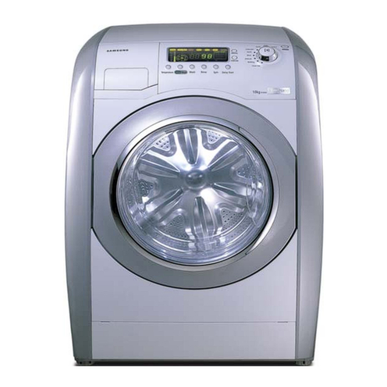
WM1255A
Refer to the service manual in the itself (http://itself.sec.samsung.co.kr/) for the more information.
WM1255AGS/XEN
BASIC MODEL
WM1245A
Manual
THE FEATURE OF PRODUCT
1. Silver Nano Sterilization,
Anti-bacteria
2. Premium Design
3. Wide Graphic Display
4. Direct Drive Motor
5. A Giant 10kg Capacity
6. 40cm Wide Porthole
7. Slanted Drum
8. Optimal Drying System
Advertisement
Table of Contents

Related Manuals for Samsung WM1255AGS/XEN


Summary of Contents for Samsung WM1255AGS/XEN
- Page 1 2. Premium Design 3. Wide Graphic Display 4. Direct Drive Motor 5. A Giant 10kg Capacity 6. 40cm Wide Porthole 7. Slanted Drum 8. Optimal Drying System Refer to the service manual in the itself (http://itself.sec.samsung.co.kr/) for the more information.
-
Page 2: Table Of Contents
CONTENTS 1. PRECAUTIONS 1-1. SAFETY PRECAUTIONS 1-2. PRECAUTIONS UPON INSTALLATION 2. THE FEATURE OF PRODUCT 2-1. PART NAMES 2-2. SPECIFICATIONS 2-3. THE COMPARATIVE SPECIFICATIONS OF PRODUCT 2-4. THE COMPARATIVE SPECIFICATIONS OF PRODUCT 2-5. WM1255A FEATURES 3. PRODUCT SPECIFICATIONS 3-1. OVERVIEW OF THE CONTROL PANEL 4. - Page 3 CONTENTS 8. BLOCK DIAGRAM 9. THE ACTUAL PCB 9-1. THE ACTUAL MAIN PCB 9-2. THE ACTUAL SUB PCB 10. SCHEMATIC-DIAGRAM 11. PCB CIRCUIT DIAGRAM 11-1. PCB CIRCUIT DIAGRAM (Main) 11-2. CIRCUIT DIAGRAMS OF MAIN PARTS 11-3. MOTOR-DRIVING PART 11-4. DISPLAY PART 12.
-
Page 4: Precautions
1. Precautions 1-1. Safety Precautions 1. Ensure that users do not repair the product themselves. ▶ This may cause harm or shorten the lifetime of the product. 2. Ensure that the power plug is disconnected before performing A/S (especially A/S for electrical parts). ▶... -
Page 5: Precautions Upon Installation
1-2.Precautions upon Installation ■ How to disassemble the safety apparatus 1. Remove the screw of the safety 2. Remove the safety apparatus from apparatus using a spanner. the back of the main body. 3. Insert the stopper into 4. Insert 4 stoppers into each the groove for fixing the groove for fixing the safety safety appratus. - Page 6 ■ Grounding ※ Make sure to ground the unit to prevent electric leakage or shock. With a grounded receptacle ▶ It does not need an additional grounding. ■ Water Drainage ▶ Hook the drain hose over the Wash Basin or Laundry Tub or plug the end of the drain hose into the Standpipe - The end of the drain hose must be passed...
- Page 7 ■ Installation Manner 1. Select an installation place in advance. ▶ The distance between the washing machine and the wall must be at least 10cm. 2. Check the balance ▶ If you press down or shake any part of the front, left or right side of the washing machine and it still wobbles, adjust the feet again until the machine is standing solidly.
-
Page 8: The Feature Of Product
THE FEATURE OF PRODUCT Part Names 2-1. Cold Water supply hose Detergent Drawer Control panel Drain Hose Door Debris filter Door release Base cover Emergency drain tube Adjustable feet - 5 -... -
Page 9: Specifications
2-2. Specifications FRONT LOADING TYPE WASH TYPE W650mm X D774mm X H939mm DIMENSION GROSS W727mm X D857mm X H1015mm 50 kPa ~ 780 kPa WATER PRESSURE 92 kg WEIGHT GROSS 99 kg WASH & SPIN CAPACITY 10.0 kg (DRY LAUNDRY) 6.0 kg DRY CAPACITY 220V... -
Page 10: The Comparative Specifications Of Product
2-3. THE COMPARATIVE SPECIFICATIONS OF PRODUCT Item 10.0kg Old (10.0kg) WM1255A WM1245A Model Name 10.0kg 10.0kg Washing Capacity Drying 6.0kg 6.0kg 78 ℓ 78 ℓ Drum Capacity DD INVERTER DD INVERTER Washing Motor Heater (220V) 1900W 1900W Cold water / Drain pump Cold water / Drain pump Supply/Drain Balancer... -
Page 11: The Comparative Specifications Of Product
2-4. THE COMPARATIVE SPECIFICATIONS OF PRODUCT 10.0kg WM1255A WM1245A Model Name Function AG+ WASH MEMORY Exterior Replacement Part Specifications Name Top Cover SNOW-WHITE SNOW-WHITE Panel-Control SNOW-WHITE SNOW-WHITE Panel-Drawer SNOW-WHITE SNOW-WHITE Cover Door IMPERIAL-SILVER IMPERIAL-SILVER Deco Top IMPERIAL-SILVER IMPERIAL-SILVER Design Deco Front IMPERIAL-SILVER IMPERIAL-SILVER Button-Push(F) -
Page 12: Wm1255A Features
2-5. WM1255A Features This washing machine performs the washing and dehydration functions by rotating its drum around a 10° inclined axis of rotation to the horizontal axis. 1. Washing The washing technique employed is to let the clothing fall from the top of the drum cycle. 2. - Page 13 4. Silver-Nano System 1) Purpose - Provides sterilization for the wash cycle using the combination of the silver ionized water and the chemical detergent. - Provides anti-bacteria feature to protect external bacteria from infiltrating into the laundry by means of silver-nano coating. - Prevents any harmful substances from growing in the tub (mold, various bacteria, bad smell, etc) 2) Driving System...
- Page 14 5. Advantages of the WM1255A (1) Maximized Anti-bacteria and Sterilization - Introducing Silver Nano Technology (2) Saves water (Washes with a smaller amount of water than 'normal' washing machines) (3) Less wear and tear on clothing (4) High-temperature washing (95 ℃ -washing) available for sterilization/hygiene purposes. (5) It is an energy saving model by employing a high-efficiency motor.
- Page 15 :200~250rpm) ~95rpm) :200~250rpm) ~95rpm) Retry Retry Retry Retry 5times 5times 10times 10times Simple Simple /Main /Main Dehydration Dedydration 3times 3times Re-supply Re-supply Next Cycle of Water of Water Cloth- untwisting Error Error End of Dehydration - 12 - Samsung Electronics...
- Page 16 Reference 2. Liquid Balance - Principle of Liquid Balance The previous drum-type washing machines used to control 'Unbalances' on the principle of weight so that the weight of the product was quite heavy, whereas this product decreases the weight by employing a liquid balance.. Unbalance Unbalance At Stop / Acceleration...
-
Page 17: Product Specifications
PRODUCT SPECIFICATIONS 3-1. OVERVIEW OF THE CONTROL PANEL 1. Cycle Display LED It displays the present operating cycle and the setup cycle. ● Pressing the Pause button displays the amount of cycles remaining. ● 2. Power Switch This switches the power ON/OFF. ●... - Page 18 - Silver Anti-bacteria: the silver nano kit starts operation in water supply for the last rinse cycle. When the silver nano key is selected, the last rinse time becomes longer than the others for ● effective anti-bacteria feature. When the silver nano key is selected, the silver nano LED turns on and when the wash or rinse ●...
- Page 19 below 55℃. - You cannot select the add laundry function during the Clean-tub course When selecting the add laundry key, if the machine is already operating, the machine stops ● temporarily. When the add laundry key is pressed, the machine stops the drum rotating and drains the ●...
- Page 20 6. Program Chart ① . Jog-dial Switch This switch enables the selection of a course in the following order: Towel ↔ Cotton ↔ Cotton 95 ℃ ↔ Cotton 75 ℃ ↔ Coloureds ↔ Quick ↔ Wool ↔ Delicate ↔ Bedding ↔ Clean Tub.
- Page 21 7. Function Buttons 1) The Function Buttons have 75±16.7ms of the effective time of pressing. 2) If the press of a Function Button is sensed, a function button sound is heard. 3) If two or more buttons are pressed, the button pressed first will be selected. (Except for special buttons (Power Button)) 4) Cases where Function Buttons are not selectable: ①...
- Page 22 3) Water Supply Function ① When selecting Wash -. Water is supplied through cold water + hot water(option) valves to the frequency level of the wash set up for each course. (The hot-water valve does not operate when the temperature is set to below 60 ℃ .) If the wash temperature is set to over 40 ℃...
- Page 23 5) SOFT KEEP ① When all cycles are done along with Drying, the END feature starts to operate. Once this is completed, if you do not remove the laundry, the washer rotates the drum in reverse to avoid wrinkles. ② The reverse-rotation continues up to 30 minutes after the completion of all cycles. ③...
-
Page 24: Alignment And Adjustments
ALIGNMENT AND ADJUSTMENTS 4-1 Error Mode Error Display Cause/Appearance of Error Way of Release Water If higher than 32kHz or lower than 10kHz of water level level sensor frequency is continuously kept for 4sec in every Power Off sensor 0.5sec measurement, this error will occur. abnormal (caused by wire-breaking of water level sensor) If AD converter data in water temp sensor become larger... - Page 25 Unplug the If AC power signal is detected for longer than 4sec even after Main relay power plug, and connection of power plug or after opening of the relay by power abnormal PCB needs to off, this error will occur. repair.
- Page 26 If the washing water temperature is increasing more than Open the main 4°C every 5sec during the operation of washing heater, this relay at once, error will occur. If higher than 100°C of the washing water is and Power will detected for longer than 6sec at the temperature sensor, this be automatically error will occur also.
-
Page 27: Troubleshooting (Test Mode)
4-2. Troubleshooting (Test Mode) 1. Troubleshooting (Test Mode) ① . Connect the power cord to the power socket. ② . Switch the Power Button on while pressing the Spin and Drying Selector buttons. ③ . All of the LEDs will be turned on in the Display window. (Check the LEDs.) If you release the button being pressed, will be displayed. - Page 28 -. Drain Pump ON/OFF -. The rinse LED turns on 5 times when A) Keep it on regardless of the operating the drain pump operates. rate. -. Fan Motor ON/OFF A) The error checking time is shortened to 6 -. 150 mins. during the fan motor seconds in test mode.
-
Page 29: Detailed Examination Of Problems
4-3. Detailed Examination of Problems The Setup of the Test Mode (Order) 1. Press the Power S/W while pressing the Spin/Drying Time buttons (This makes a beeping sound [as in beep-beep], and turns on all of the LEDs - check the condition of the buzzer and the LED.) 2. -
Page 30: Assembly And Disassembly
ASSEMBLY AND DISASSEMBLY 5-1. TOOLS FOR DISASSEMBLY AND ASSEMBLY Tool Heater(1),Tub(16), Fixer screw(5) 10㎜ Box driver 13㎜ Motor(1), Balance(5), Shock Absorber (2 holes each in 19㎜ left/right), Pulley(1) ,Damper(oil)(2), Damper(friction 1) Double-ended Replaced by box driver 10, 13, 19㎜ spanner A Tool for protecting empty turning of bolt or abrasion Vice pliers from using box driver... - Page 31 5-2. ASSEMBLY AND DISASSEMBLY Part Name Figure Method of Repair Disassembly Order MOTOR 1.Disassemble the two screws used to fix the Back Cover. Separate the Back Cover and remove the M19 nut used to fix the Motor. (Caution: Turn counterclockwise to release. Turning slowly will make it more difficult to disassemble, since the motor may rotate at the same time.
- Page 32 Part Name Figure Method of Repair Exchangin 1. Remove the four screws on the back. g the Sub and the Power S/W ① 2. Separate the Deco top (L,R) by pushing it backwards. Remove the two screws used to fix the Cover top. Remove the screws used to fix the Deco Front (L,R) with the Cover Top.
- Page 33 Part Name Figure Method of Repair ① 1. Put an I-type screwdriver into the gap between Drain the Cover Front (L) and the Cover Front Panel PUMP and press downdwards to separate the hook. . Turn the Cap Drain Hose anti-clockwise and separate it from the Frame front (L).
- Page 34 Part Name Figure Method of Repair Door S/W 1.Open the Door. ① 2. Remove the Spring Diaphragm. (It is easy to remove if you first pull out the spring placed at the lower part of the Diaphragm using a I-type screwdriver.) ※...
- Page 35 Part Name Figure Method of Repair 1. Remove the two screws used to fix the Back Cover - Remove the Back Cover Heater/ - Remove the Cap at ( 가 ) region Thermostat (가) ① 2. Remove the connection wire - Separate the Thermostat fixed on the lower part of the Tub by inclining the set 30°...
- Page 36 Part Name Figure Method of Repair Exchangin 1. Remove the four screws on the back. g the Main PCB ① 2. Remove the Deco top L,R by pushing it backwards from the front. ( → See the direction of the arrow) Remove the four screws used to fix the Cover top.
- Page 37 Part Name Figure Method of Repair 1. Separate the Deco top, Top cover. Water ① - Separate the screws used to fix the Water Supply Supply Valve. Valve - Separate the Valve Wire. - Separate the Valve Hose. OPTION Check Trouble Points 1.Hot water-(opton), Main-, and Pre-valves function by pressing the Water Temperature Button in Test mode.
- Page 38 Part Name Figure Method of Repair You can locate the silver kit inside the housing Silver kit drawer by removing the cover. - Remove the water hose connected between the housing drawer and the silver kit. - Untie the two cable ties on the cover PCB of the silver kit.
- Page 39 Part Name Figure Method of Repair Condenser 1. Remove the Deco top & Top cover Replacement - Loosen the screws - Remove the connector Check Point 1. Check for damage to the outer look and the terminals Belt / Check Point 1.
- Page 40 Part Name Figure Method of Repair Thermostat 1. Remove the connector - Loosen the screws Replacement ※ Note: the two thermostats are different from each other with regard to their properties. Difference : Auto type - no press system in the center (90' marked point on the dry duct surface) Manual Type - a press system in the center...
- Page 41 Part Name Figure Method of Repair Heater 1. Remove the frame plate U - Loosen the screws between the housing fan "U" Replacemen and "L" - Loosen the screws between the housing fan "U" and the tub (Point A) 2. Loosen the three screws for fixing the heater Check Point 1.
-
Page 42: Trouble Diagnosis
Trouble Diagnosis 6-1. Related Parts to Errors for Checking Error 5E (Drain abnormal):Drain not worked. dE (Door open) dE1(Door switch abnormal) Door switch not worked. dE2(Door being continuously worked) Not worked. UE(Unbalance abnormal)Dehydration not worked. HE(Heater abnormal) HE1(Heater abnormal): HEATING not worked. - Page 43 Error 17 13E(Communication abnormal) tE(Thermister abnormal:HEATING HEATER) tE2(Thermister abnormal: Condensing Thermister) tE3(Thermister abnormal: Drying Thermister) 8E(Hot/Cold Water Hoses wrong connected each other) 22 14E(Button being pressed) 23 CE(Cooling abnormal) 24 FE(Drying Motor abnormal) 25 F(Overload detected) 26 Vibration high 27 Not powered - 40 -...
-
Page 44: Exploded Views And Parts List
Exploded Views and Parts List 7-1. Exploded View of Whole Parts - 41 -... -
Page 45: Exploded View Of Detergent Tray/Sub Pcb
7-2. Exploded View of Detergent Tray/SUB PCB Y0162 C0103 C0081 C0043 C0056 C0044 Y0066 C0029 R0014 C0105 C0082 Y0066 C0029 A0128 C0055 A0329 C0002 - 42 -... -
Page 46: Parts List Of Detergent Tray/Sub Pcb
CODE NO. DESCRIPTION SPECIFICATION SA/SNA C0103 3405-001067 SWITCH-MICRO 125/250VAC,15A/0.1A,200GF,S C0105 DC64-00505E BUTTON-ENCODER H1245A,ABS,SNOW-WHT,C C0029 DC97-06253A ASSY-KNOB ENCODER SD100,ASSY-ENCODER C0002 DC97-09568C ASSY-PANEL CONTROL WM1255AGS/XEN,DUTCH/1 C0044 DC64-00854A BUTTON-PUSH(P) WC1235A,ABS,POWER C0055 DC64-00855A DECORATION-BUTTON(F) WC1235A,ABS C0056 DC64-00856A DECORATION-BUTTON(P) WC1235A,ABS A0329 DC64-00859A INLAY-ENCODER WC1235A,PC Y0162 MFS-WM1255A-S0... -
Page 47: Exploded View Of Tub/Damper/Main/Motor Pcb
7-4. Exploded Views of TUB/Damper/Main/Motor PCB U0095 U0221 W0035 U0198 F0005 U0071 U0064 U0163 H0075 U0201 R0001 U0202 U0358 S0058 R0158 U0013 U0137 I0043 W0004 U0038 U0029 U0061 U0061 F0224 U0061 J0013 I0043 I0071 Y0161 U0359 R0125 - 44 -... -
Page 48: Parts List Of Tub/Damper/Main/Motor Pcb
7-5. Parts List of TUB/Damper/Main/Motor PCB CODE NO. DESCRIPTION SPECIFICATION SA/SNA H0075 DC31-00049A MOTOR-DRUM NEWMOTECH,SEW-HW125,1 F0224 DC67-00060A WEIGHT-BALANCER TS85-PJT,FE,LOWE U0095 6602-001177 BELT-TIMING GEAR EL416H3,POLYURETHAN,T2. U0198 DC31-00044B MOTOR-FAN WDS020ATVA,50Hz,22 W0035 DC32-00004B THERMISTOR 40KOHM(4020~170,5V, F0005 DC47-00002C THERMOSTAT SDF-V501,250V,16A,145 F0005 DC47-00003C THERMOSTAT Z-12,250V,16A,90,75 U0163 DC47-00012B HEATER-DRY... -
Page 49: Exploded View Of Frame Front/Assy Door
7-6. Exploded View of Frame front/Assy Door R0065 R0030 D0045 D0004 F0064 C0058 D0010 A0355 D0107 D0061 - 46 -... -
Page 50: Parts List Of Frame Front/Assy Door
7-7. Parts List of Frame front/Assy Door CODE NO. DESCRIPTION SPECIFICATION SA/SNA D0004 DC97-04959A ASSY-HINGE TS85-PJT,STS304 D0045 DC97-04968A ASSY-HOLDER GLASS TS85-PJT,FRPP/WHT D0010 DC97-04969M ASSY-COVER DOOR SEW-HR125Q,SILVER/METAL- A0355 DC66-00360A LEVER SEW-HW125,LDPE(XZ700),L292 C0058 DC64-00519A DOOR-LOCK S/W DW100,NYLON,WHT,VD R0065 DC63-00370B COVER-FRONT PANEL SEW-HW126,ABS, F0064 DC97-04961A ASSY-FRAME FRONT... -
Page 51: Exploded View Of Frame
7-8. Exploded View of Frame R0073 R0160 P0053 R0070 F0125 A0351 R0159 Y0162 A0351 R0021 I0003 W0032 I0068 R0158 R0105 R0020 R0104 Q0006 A0352 R0104 R0105 I0068 R0103 R0019 A0282 A0086 I0022 W0036 A0086 F0062 I0040 A0358 B0070 - 48 -... -
Page 52: Parts List Of Frame
7-9. Parts List of Frame CODE NO. DESCRIPTION SPECIFICATION SA/SNA I0003 DC67-00089A HOSE-WATER SEW-HW125,EPDM,ID5,OD9,T2,L70 I0040 DC62-10289B HOSE-WATER(C) WIP4013SRW,PVC+NYLON,ID10. A0282 DC63-00375D COVER-BACK SEW-HW125,GI,T0.5,NO- I0022 DC97-00139V ASSY-HOSE DRAIN(O) V7-PJT,PP/L2000 A0351 DC61-00912A SPRING-HANGER TS85-PJT,SWC,CD2.0,ID14,OD B0070 DC97-06665A ASSY-LEG TS-85,ASSY-LEG F0125 DC61-01159A FRAME-PLATE(U) SEW-HR125,HOT-GI,T1 A0358 DC63-00374B COVER-FRONT(L) SEW-HW126,ABS,S... - Page 53 7-10. Parts List (SA) CODE NO. DESCRIPTION SPECIFICATION SA/SNA Z0036 6001-001668 SCREW-MACHINE TH,+,M5,L16,PASS,STS430,FP Z0027 6001-001773 SCREW-MACHINE TH,+,M5,L12,STS430,S Z0010 6002-001006 SCREW-TAPPING TH,+,2S,M4,L12,STS410, Z0013 6002-001279 SCREW-TAPPING PWH,+,1,M4,L12,PASS,STS304 D0106 DC63-00369M COVER-DOOR SEW-HR125Q,ABS,AQUQ D0055 DC64-00484A DECORATION-LID TS85-PJT,ABS,NI D0066 DC64-00485A DOOR-SAFETY TS85-PJT,PC,PRN C0093 DC61-00982A SPRING-BUTTON(P) SEW-3HW125,STS304 W0001 DC96-00570B...
- Page 54 CODE NO. DESCRIPTION SPECIFICATION SA/SNA N0004 DC61-60497A CLAMPER HOSE SWF-P12,HSWR,ID70/OD75.8, U0016 DC62-00156A SEAL-OIL TS85-PJT,NBR(SD45.5),BLK U0363 DC63-00512A COVER-HEATER SEW-HW125,SBHG1-A,T0.5, U0364 DC69-00633A PACKING-TUB TS85-PJT,EPDM-FOAM,L18 I0039 DC97-08272A ASSY-HOSE DRAIN SEW-5HR120,DRAIN+PRESSUR N0010 DC65-00009A CLAMPER HOSE TS85-PJT,HSWR,YEL,OD24/ U0183 DC67-00120A HOSE-JOINT AIR SEW-3HW1232,PP,ID15,OD20, U0078 DC97-08148C ASSY-SEMI TUB BACK K1~V7 DRY,SGEC/BEARIN U0062 DC97-05666B...
- Page 55 CODE NO. DESCRIPTION SPECIFICATION SA/SNA Z0037 6002-001307 SCREW-TAPPING TH,+,1,M5,L16,PASS Z0019 6006-001170 SCREW-TAPPING TH,+,WT,TC,M4,L10,ZPC(YEL) R0029 DC96-00772A ASSY-TRANS REACTORV TS85-PJT,220V/60Hz R0012 DC97-04962D ASSY-COVER FRONT K1,NO-SPRAY/NO-LABEL N0006 DC61-40081A HOLDER-WIRE DAWH-2NC,NYLON66,NTR R0036 DC61-00824A BODY-DRAWER TS85-PJT,PP(TB-53),W R0025 DC97-04971T ASSY-PANEL DRAWER TS-85,GB R0122 DC61-00902A SPRING-DRAWER TS85-PJT,STS304,CD0.6, P0001 DC97-05452E ASSY-COVER TOP...
-
Page 56: Block Diagram
BLOCK DIAGRAM... -
Page 57: The Actual Pcb
9. The Actual PCB 9-1. The Actual MAIN PCB 7. Hall Sensor Port: Hall Sensor Power, Data 1. PCB Power: The voltage between two ends (220V) 8. Sensor System: Thermistor, Water Level Sensor, 2. Noise Filter: Noise Filtering System Door Lock Sensor 3. -
Page 58: The Actual Sub Pcb
9-2. The Actual SUB PCB Course Selection Dial Cotton Cotton Drying Silver Wash Number Spin Speed 95℃ Washing COTTON 75℃ Selector Wash Course Selection of Rinse Setup Temp. Setup COLOUREDS TOWEL Setup QUICK WOOL DELICATES BEDDING CLEAN TUB COURSE SELECTION DIAL - 55 -... -
Page 59: Schematic-Diagram
10. SCHEMATIC-DIAGRAM... -
Page 60: Pcb Circuit Diagram
11. PCB CIRCUIT DIAGRAM This Document can not be used without Samsung's authorization. 11-1. PCB CIRCUIT DIAGRAM (Main) -
Page 61: Circuit Diagrams Of Main Parts
11-2. Circuit Diagrams of Main Parts 1.Power Power Press of Power S/W switches NC to NO and makes Micom start to drive. At this moment, sequential sigals generated from Micom function to operate Power Relay continuously. One more press of Power S/W switches NC to NO and permits Micom to accept the signal. It will cut off Power by switching the Relay ON/OFF. -
Page 62: Motor-Driving Part
11-3. MOTOR-Driving Part A voltage of DC 300V is sent from MIG10j503 to Motor through Power Line, and Hall Sensor checks the rotation through feedback of the signal into Main Micom(TMP88PS43F) when Motor is being rotated. Power Line Hall sensor - 59 -... -
Page 63: Display Part
11-4. Display Part TMP88CS42N Water Temperature & Level Sensors Water Level Sensing Water Temp Sensing TMP88CS42N - 60 -... -
Page 64: Reference Information
12. REFERENCE INFORMATION 12-1. MODEL NAME Actual Model Name in the Market BOM Model Code Option A : AG+ Wash Buyer Drum INTRO machine YR 2005 classification RPM Notation according to 1000rpm : 10 Alphanumeric notaton type : 1200rpm : 12 based on the color, WM (Washer &... -
Page 65: Terminology
12-2. TERMINOLOGY 1) ASSY-MAIN PCB (Imbalance Sensor) → To prevent the laundry from gathering on one side of the tube causing noise and vibration, the washing machine uses an imbalance detection device that evenly disentangles the laundry before the hydrating cycle starts. 2) DOOR-LOCK S/W →... - Page 66 9) PRE-WASH → The machine does a preliminary wash of about 10 minutes prior to the main wash. This is particularly effective for cleaning badly stained laundry. 10) WEIGHT SENSOR → The tube automatically rotates when no water is supplied to detect the laundry weight so that the proper wash time can be determined.
-
Page 67: Fabric Care Chart
12-3. FABRIC CARE CHART Can be ironed at 100 û C max Resistant material Do not iron Delicate fabric Can be dry cleaned using any solvent Item may be washed at 95 C Dry clean with perchloride, lighter fuel, Item may be washed at 60 C pure alcohol or R113 only Dry clean with aviation fuel, Item may be washed at 40 C... -
Page 68: Q&A
12-5. Q & A Q1. The machine does not respond to my keystrokes even while operating. Check if Child Lock is on. To switch it off, see the User Guide. Q2. The hydration time in the Drying course is set to 17 minutes. Can I change the time in any way? We have extended the hydration time for faster drying. - Page 69 Q10. While operating, the time disappears temporarily in the last hydration cycle and returns with another time. Is this an error? The machine detects the laundry weight before the hydration cycle and determines the final drying time. The drying time will then disappear for a moment. The initial drying time is changed to a more accurate drying time before being displayed.
- Page 70 Q18. What is the difference between anti-bacteria and sterilization? Sterilization is a process that initially gets rid of up to 35000 different bacteria into asepsis. In the meantime, anti-bacteria is a process that injects a small number of bacteria in the asepsis conditions and checks how many bacteria survived after 18 hours.
- Page 71 Solut ion Type Part Situati on Before consu lti ng cause method ☞ Door is DRUM appearance part Being opened & closed In case of a cover not being opened or closed WASHER bad/Being attached & rerecomm drying the d detached bad ended safe level.
- Page 72 상담 DRUM a noise Water leakage being occurred Lead to reassembe when water supply hose is Disconnect WASHER at water supply connection departed. ☞ If the det DRUM water leakage Water being overflowed from General It may be used with so much detergent or left WASHER related detergent box(front loading...
- Page 73 ☞ Disconne DRUM 4E :front loading Water level sensor inferiority This may be happened when there is any WASHER washing machine rerecomm foreign material inside the water supply and drain material inse error ended valve or the interior components of the prodcuts do not operate normally.
- Page 74 ▶ Is it chec DRUM water supply Water being supplied little General It may appear when the tap is not opened WASHER related consulting properly or there is a foreign material inside. inserted? ☞ the hose of entrance. C ☞ Sove the DRUM water supply Detergent being remained...
- Page 75 ▶Check wh DRUM dehydrating Not being squeezed well General It may appear when there are clothes like vinyl. WASHER related consulting prevent the request an e ☞ There ma DRUM dehydrating Water being in at purchasing WASHER related rerecomm products tes ended ☞...
- Page 76 ELECTRONICS © Samsung Electronics Co., Ltd. September 2005 This Service Manual is a property of Samsung Electronics Co.,Ltd. Printed in Korea Any unauthorized use of Manual can be punished under applicable International and/or domestic law. Code No. : DC68-02081A...
Need help?
Do you have a question about the WM1255AGS/XEN and is the answer not in the manual?
Questions and answers