
Related Manuals for Microchip Technology EVB-LAN9252-3PORT


Summary of Contents for Microchip Technology EVB-LAN9252-3PORT
-
Page 1: Evaluation Board
EVB-LAN9252-3PORT ® EtherCAT PHY Connection Mode Evaluation Board User’s Guide 2015 Microchip Technology Inc. DS50002403A... - Page 2 SQTP is a service mark of Microchip Technology Incorporated in the U.S.A. Silicon Storage Technology is a registered trademark of Microchip Technology Inc. in other countries. GestIC is a registered trademark of Microchip Technology Germany II GmbH & Co. KG, a subsidiary of Microchip Technology Inc., in other countries.
- Page 3 Object of Declaration: EVB-LAN9252-3PORT 2015 Microchip Technology Inc. DS50002403A-page 3...
- Page 4 ® EVB-LAN9252-3PORT EtherCAT ESC PHY Connection Mode User’s Guide NOTES: 2015 Microchip Technology Inc. DS50002403A-page 4...
-
Page 5: Table Of Contents
3.2.5 SoC ......................22 3.3 Mechanicals ....................24 Appendix A. EVB-LAN9252-3PORT Evaluation Board A.1 Introduction ....................25 Appendix B. EVB-LAN9252-3PORT Evaluation Board Schematics B.1 Introduction ....................27 Appendix C. Bill of Materials (BOM) C.1 Introduction ....................39 Worldwide Sales and Service ..................44 ... - Page 6 ® EVB-LAN9252-3PORT EtherCAT ESC PHY Connection Mode User’s Guide NOTES: 2015 Microchip Technology Inc. DS50002403A-page 6...
-
Page 7: Preface
Development Systems Customer Change Notification Service • Customer Support • Document Revision History DOCUMENT LAYOUT This document describes how to use the EVB-LAN9252-3PORT as a development tool ® for the Microchip LAN9252 EtherCAT slave controller. The manual layout is as follows: •... -
Page 8: Conventions Used In This Guide
Curly brackets and pipe Choice of mutually exclusive errorlevel {0|1} character: { | } arguments; an OR selection Ellipses... Replaces repeated text var_name [, var_name...] Represents code supplied by void main (void) user { ... 2015 Microchip Technology Inc. DS50002403A-page 8... -
Page 9: The Microchip Web Site
PICSTART Plus and PIC-kit 2 and 3. CUSTOMER SUPPORT Users of Microchip products can receive assistance through several channels: • Distributor or Representative • Local Sales Office • Field Application Engineer (FAE) • Technical Support 2015 Microchip Technology Inc. DS50002403A-page 9... -
Page 10: Document Revision History
Technical support is available through the web site at: http://www.microchip.com/support DOCUMENT REVISION HISTORY Revision A (August 2015) • Initial Release of this Document. Revision B (August 2015) • Updated Appendix C. “Bill of Materials (BOM)”. 2015 Microchip Technology Inc. DS50002403A-page 10... -
Page 11: Chapter 1. Overview
3-port mode and its jumper configurations. The LAN9252 is connected to an RJ45 Ethernet jack with integrated magnetics for 100BASE-T connectivity. A simplified block diagram of the LAN9252 can be seen Figure 1-1. 2015 Microchip Technology Inc. DS50002403A-page 11... -
Page 12: References
• SPI - Serial Protocol Interface • 100BASE-TX- 100 Mbps Fast Ethernet, IEEE802.3u Compliant • GPIO - General Purpose I/O • MII - Media Independent Interface • RMII - Reduced Media Independent Interface 2015 Microchip Technology Inc. DS50002403A-page 12... -
Page 13: Chapter 2. Board Details
80ms CLOCK LAN9252 requires an external 25Mhz crystal or clock. By default, Short 1-2 of J14 header to connect the 25 MHz crystal Y1 to the internal oscillator of the LAN9252. 2015 Microchip Technology Inc. DS50002403A-page 13... -
Page 14: Chapter 3. Board Configuration
EEPROM Strap Microchip LAN9252 Port 1 Port 2 (with integrated (with integrated magnetics & LEDs) magnetics & LEDs) Note: 3-port Mode: Port 1 and Port 2 both are Internal, Port 0 is External. 2015 Microchip Technology Inc. DS50002403A-page 14... -
Page 15: External Phy Connection Mode
The default jumper settings for the LAN9252 are given below in Table 3-1. TABLE 3-1: DEFAULT JUMPER SETTINGS Jumper Pin Settings J4 & J7 J5 & J8 J6 & J9 J15 & J16 J19,J20,J21,J22 & J23 OPEN 2015 Microchip Technology Inc. DS50002403A-page 15... -
Page 16: Strap Options
They can also be used as GPIOs, LED drivers. When used as LED drivers, as they are on the EVB-LAN9252-3PORT, they are connected a specific way to set the strap value to a “1”, and another way to set the strap value to a “0”. Figure 4 illustrates the sche- matics connections with the D3 circuit as a pull-up, and the D4 circuit as a pull-down. - Page 17 Copper Mode is active. Fiber Mode is supported as an assembly option. To select the Copper or Fiber Mode, the respective strap and signal routing resister assembly options must to be configured. Note: Vendor part number for SFP: Finisar/FTLF1217P2 2015 Microchip Technology Inc. DS50002403A-page 17...
- Page 18 ® EVB-LAN9252-3PORT EtherCAT ESC PHY Connection Mode User’s Guide 3.2.1.4.1 Copper Mode Strap The EVB-LAN9252-3PORT is set to Copper Mode by default. Table 3-5 details the required strap resistor settings for Copper Mode operation. TABLE 3-5: COPPER MODE STRAP RESISTORS...
-
Page 19: Led Indicators
Board Configuration 3.2.1.4.3 FX-LOS Fiber Mode Strap The EVB-LAN9252-3PORT is set to Copper Mode by default. Table 3-9 details the required strap resistor settings for FX-LOS Fiber Mode operation. TABLE 3-9: FX-LOS FIBER MODE STRAP RESISTOR SETTINGS Reference R77 (10K) -
Page 20: Spi + 3 Port Mode Selection
3.2.4.3.1 Assembly of the Boards The MII Female Connector (J27) is used to connect External PHY Board. EVB-LAN8740 MII PHY Board have been used as External PHY Board as shown in Figure 3-2. 2015 Microchip Technology Inc. DS50002403A-page 20... - Page 21 The EVB-LAN8740 is used for an External PHY. Refer to link http://ww1.microchip.com/downloads/en/DeviceDoc/evb8740_user.pdf more details on EVB-LAN8740. Remove on board crystal and connect MII-CLK25 from MII connector to the LAN8740 OSCO pin as shown below in Figure 3-5 (through Green wire). FIGURE 3-5: LAN8740 2015 Microchip Technology Inc. DS50002403A-page 21...
-
Page 22: Soc
3.3V o/p to reset release. 3.2.5.4 ICSP HEADER The programing is done using the ICSP header – J13. Table 3-17 shows the PIN details of J13. TABLE 3-17: J13 PIN DETAILS J13 PIN No Signals Detail MLCR 2015 Microchip Technology Inc. DS50002403A-page 22... - Page 23 ID_SELECT_RB5 SW7.6 R128 ID_SELECT_RB8 SW7.7 R129 ID_SELECT_RB9 SW7.8 R130 ID_SELECT_RB10 SW8.1 R131 ID_SELECT_RB11 SW8.2 R133 ID_SELECT_RB12 SW8.3 R134 ID_SELECT_RB13 SW8.4 R132 ID_SELECT_RC1 SW8.5 R135 ID_SELECT_RC2 SW8.6 R136 ID_SELECT_RC3 SW8.7 R137 ID_SELECT_RC4 SW8.8 R138 2015 Microchip Technology Inc. DS50002403A-page 23...
-
Page 24: Mechanicals
® EVB-LAN9252-3PORT EtherCAT ESC PHY Connection Mode User’s Guide MECHANICALS Figure 3-6 details EVB-LAN9252(SPI + 3 Port) mechanical dimensions. Dimensions are in mm. FIGURE 3-6: EVB-LAN9252 MECHANICAL DIMENSIONS 2015 Microchip Technology Inc. DS50002403A-page 24... -
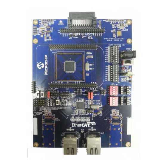
Page 25: Appendix A. Evb-Lan9252-3Port Evaluation Board
EVB-LAN9252-3PORT ® ETHERCAT ESC PHY CONNECTION MODE USER’S GUIDE Appendix A. EVB-LAN9252-3PORT Evaluation Board INTRODUCTION This appendix shows the EVB-LAN9252-3PORT Evaluation Board. FIGURE A-1: EVB-LAN9252-3PORT EVALUATION BOARD 2015 Microchip Technology Inc. DS50002403A-page 25... - Page 26 ® EVB-LAN9252-3PORT EtherCAT ESC PHY Connection Mode User’s Guide NOTES: 2015 Microchip Technology Inc. DS50002403A-page 26...
-
Page 27: Appendix B. Evb-Lan9252-3Port Evaluation Board Schematics
EVB-LAN9252-3PORT ® ETHERCAT ESC PHY CONNECTION MODE USER’S GUIDE Appendix B. EVB-LAN9252-3PORT Evaluation Board Schematics INTRODUCTION This appendix shows the EVB-LAN9252-3PORT Evaluation Board Schematics. 2015 Microchip Technology Inc. DS50002403A-page 27... - Page 28 FIGURE B-1: BLOCK DIAGRAM BLOCK DIAGRAM :...
- Page 29 FIGURE B-2: POWER SUPPLY & RST POWER SUPPLY 3 V REGULATOR, 3A ORANGE ORANGE ( 3V3 fixed when Rb=503e) BLACK BLACK BLACK BLACK 5V_EXT 5V_SW VOUT EN12_1 ENABLE TRIM 2A/0.05DCR 2A/0.05DCR Switch, SPDT, Slide Switch, SPDT, Slide 3_Amp 3_Amp 470E 470E 4.7uF 4.7uF...
- Page 30 FIGURE B-3: LAN9252 Power Supply Filtering VDD33TXRX1 2A/0.05DCR 2A/0.05DCR VDDCR VDD12TX1 VDD12TX2 1.0uF 1.0uF 0.1uF 0.1uF VDD33TXRX2 2A/0.05DCR 2A/0.05DCR VDDCR 2A/0.05DCR 2A/0.05DCR 1.0uF 1.0uF 0.1uF 0.1uF BLM18EG221SN1D BLM18EG221SN1D 2A/0.05DCR 2A/0.05DCR Note: OSCVSS need to connect to Chip gnd. R166 R166 100K 100K HEADER 3X2...
- Page 31 FIGURE B-4: COPPER MODE INTERFACE VDD33TXRX1 Pulse J0011D01BNL Pulse J0011D01BNL 49.9 49.9 49.9 49.9 49.9 49.9 49.9 49.9 1/10W 1/10W 1/10W 1/10W 1/10W 1/10W 1/10W 1/10W RJ45 RJ45 XMIT XMIT TXPA FX_SFP-TXPA COP-TXPA 4 & 5 4 & 5 TXCT TXNA FX_SFP-TXNA COP-TXNA...
- Page 32 FIGURE B-5: SFP INTERFACE Note:Place Note:Place capacitors, capacitors, Fiber Port 1 :SFP Interface Fiber Port 0 :SFP Interface and resistors and resistors close to FOT close to FOT 49.9 49.9 49.9 49.9 49.9 49.9 49.9 49.9 0.1uF 0.1uF 0.1uF 0.1uF FX_SFP-RXNA FX_SFP-RXNB 0.1uF...
- Page 33 FIGURE B-6: STRAP, GPIO, I C & FXLOS GPIO [0:2] & LED_POL_Strap I2C EEPROM GPIO0 GPIO2 GPIO1 MII_LINKPOL GPIO0 GPIO1 GPIO2 0.1uF 0.1uF LED0_ANODE LED1_ANODE LED2_ANODE LEDPOL6_ANODE R139 R139 10.0K 10.0K 10.0K 10.0K 10.0K 10.0K 10.0K 10.0K LED0_CATHODE LED1_CATHODE I2C2_1 I2C2_SDA LED2_CATHODE LEDPOL6_CATHODE...
- Page 34 FIGURE B-7: B2B INTERFACE Host SOC EEPROM 0.1uF 0.1uF I2C3_1 I2C1_SDA I2C3_2 I2C3_3 I2C3_7 I2C1_SCL SW DIP-4/SM SW DIP-4/SM I2C EEPROM 24FC512 24FC512 Only for Host SOC PME_LATCH1 FIFOSEL_LATCH0 TP10 TP10 HEADER 23x2 HEADER 23x2 ORANGE ORANGE VDD3V3EXP VDD3V3EXP VDD_5V VDD_5V 5V power to HOST SOC board...
- Page 35 FIGURE B-8: PIM+ON-BOARD-PIC32MX RST_GPIO STORM_SIO3 STORM_SIO2 0.1uF 0.1uF 10uF 10uF PIM1 PIM1 AERXERR VSS4 11pF 11pF SOSCO/T1CK/CN0/RC14 PMD5 SOSCI/CN1/RC13 32Khz 32Khz PMD6 INT0 PMD7 EMDC ID_SELECT_RC1 PMCS2 Aardvark / SPI Storm- Connector ID_SELECT_RC2 11pF 11pF SS1/IC2/RD9 ID_SELECT_RC3 EMDIO ID_SELECT_RC4 AETXEN I2C2_SCL PMA5 AETXCLK...
- Page 36 FIGURE B-9: EXPANSION MODE INTERFACE MII_RXD0 A4/DIGIO12/GPI12/GPO12/MII_RXD0 MII_RXDV A3/DIGIO11/GPI11/GPO11/MII_RXDV MII_LINKPOL A2/ALEHI/DIGIO10/GPI10/GPO10/LINKACTLED2/MII_LINKPOL/LEDPOL6 MII_CLK25 A1/ALELO/OE_EXT/MII_CLK25 MII_RXD3 RD/RD_WR/DIGIO15/GPI15/GPO15/MII_RXD3 MII_RXD2 WR/ENB/DIGIO14/GPI14/GPO14/MII_RXD2 MII_RXD1 CS/DIGIO13/GPI13/GPO13/MII_RXD1 MII_RXER A0/D15/AD15/DIGIO9/GPI9/GPO9/MII_RXER MII_TXD3 D14/AD14/DIGIO8/GPI8/GPO8/MII_TXD3/TX_SHIFT1 MII_TXD2 D13/AD13/DIGIO7/GPI7/GPO7/MII_TXD2/TX_SHIFT0 MII_TXD1 D12/AD12/DIGIO6/GPI6/GPO6/MII_TXD1 MII_TXD0 D11/AD11/DIGIO5/GPI5/GPO5/MII_TXD0 MII_TXEN D10/AD10/DIGIO4/GPI4/GPO4/MII_TXEN SPI_CLK D9/AD9/LATCH_IN/SCK MII_MDIO D8/AD8/DIGIO2/GPI2/GPO2/MII_MDIO MII_MDC PME_LATCH1 SYNC/LATCH1 D7/AD7/DIGIO1/GPI1/GPO1/MII_MDC MII_RXCLK D6/AD6/DIGIO0/GPI0/GPO0/MII_RXCLK FIFOSEL_LATCH0 SPI_CE#...
- Page 37 FIGURE B-10: ENHANCED LINK DETECTION Standard Link Detection Standard Link Detection 0.1uF 0.1uF 0.1uF 0.1uF R147 R147 R145 R145 R146 R146 10.0K 10.0K R148 R148 R150 R150 ZERO ZERO R149 R149 10.0K 10.0K ZERO ZERO 5V_Delay RESET R151 R151 RST_Delay SENSE ZERO ZERO...
- Page 38 ® EVB-LAN9252-3PORT EtherCAT ESC PHY Connection Mode User’s Guide NOTES: 2015 Microchip Technology Inc. DS50002403A-page 38...
-
Page 39: Appendix C. Bill Of Materials (Bom)
EVB-LAN9252-3PORT ® ETHERCAT ESC PHY CONNECTION MODE USER’S GUIDE Appendix C. Bill of Materials (BOM) INTRODUCTION This appendix includes the EVB-LAN9252-3PORT Evaluation Board Bill of Materials (BOM). 2015 Microchip Technology Inc. DS50002403A-page 39... - Page 40 TABLE C-1: EVB-LAN9252-3PORT EVALUATION BOARD BILL OF MATERIALS Manufacturer Part Item Reference Part PCB Footprint Manufacturer Number C2,C4 10uF CAP0805 Murata GRM21BR61E106KA73L C3,C5,C6,C8,C10,C11,C13,C14,C15, 0.1uF CAP0603 Murata GRM188R71E104KA01D C16,C17,C18,C21,C22,C24,C25,C58, C59,C61,C67,C68,C69,C70,C71,C72, C73,C74,C75,C84 CAP0603 Murata GRM188R61C105KA93D 470pF CAP0603 Murata GRM033R71E471KA01D C26,C27 18pF CAP0603...
- Page 41 TABLE C-1: EVB-LAN9252-3PORT EVALUATION BOARD BILL OF MATERIALS (CONTINUED) Manufacturer Part Item Reference Part PCB Footprint Manufacturer Number R4A,R160,R161 RES0603 BOURNS CR0603-FX-33R0ELF 4.75K RES0603 Panasonic ERJ-3EKF4751V R6,R69,R70,R71,R139 10.0K RES0603 Panasonic ERJ-3EKF1002V 100E RES0603 Panasonic ERJ-3EKF1000V 2.2K RES0603 Panasonic ERJ-3GEYJ222V 12.1K...
- Page 42 TABLE C-1: EVB-LAN9252-3PORT EVALUATION BOARD BILL OF MATERIALS (CONTINUED) Manufacturer Part Item Reference Part PCB Footprint Manufacturer Number PIC32MX795F512L-80I/PT IC_TQFP100_12x12x1-0p4mm No Microchip PIC32MX- 795F512L-80I/PT-ND Citizen America XTAL_HCM49 Cardinal Components CSM1Z-A5B2C5-40-25.0D Inc. 18-F 32Khz TH_XTAL_ECS-31X_32KHZ ECS INC XC1392-ND 8 Mhz th_hc49us_2p...
- Page 43 TABLE C-2: DNP COMPONENTS (CONTINUED) Manufacturer Part Item Reference Part PCB Footprint Manufacturer Number C38,C39,C40,C41,C42,C43,C44,C45, 0.1uF CAP0603 DNP Murata GRM188R71E104KA01D C47,C49,C51,C53,C55,C57 C46,C48,C50,C52,C54,C56 10uF CAP_B_3528 DNP Kemet B45190E3106K209 C80,C81 CAP0603 J2,J3 FTLF1217P2 CONN_FX_SFP_FTLF1217P2 DNP Finisar 775-1011-ND L1,L2,L3,L4 L0805 DNP Panasonic ERJ-3GEY0R00V R16,R18,R20,R22,R30,R32,R34,R36 RES0402 DNP Panasonic...
-
Page 44: Worldwide Sales And Service
Tel: 886-2-2508-8600 China - Xian Tel: 631-435-6000 Tel: 86-29-8833-7252 Fax: 886-2-2508-0102 San Jose, CA Fax: 86-29-8833-7256 Thailand - Bangkok Tel: 408-735-9110 Tel: 66-2-694-1351 Canada - Toronto Fax: 66-2-694-1350 Tel: 905-673-0699 Fax: 905-673-6509 07/14/15 2015 Microchip Technology Inc. DS50002403A-page 44...
Need help?
Do you have a question about the EVB-LAN9252-3PORT and is the answer not in the manual?
Questions and answers