Table of Contents
Advertisement
Advertisement
Table of Contents

Subscribe to Our Youtube Channel
Related Manuals for Shindaiwa DGK150D/EPA3


Summary of Contents for Shindaiwa DGK150D/EPA3
- Page 1 SERVICE MANUAL /EPA3 File№ DGO-292_DGK150D/EPA3...
- Page 2 This service manual is edited for authorized person to perform repair, maintenance, and trouble-shooting to Shindaiwa Diesel Engine Generator, Model DGK150D/EPA3. It is inevitably necessary to maintain and adjust Shindaiwa products periodically in order to use fully and safely for long time. Therefore, understand this service manual fully enough before use and proper maintenance.
-
Page 3: Table Of Contents
Table of Contents 1. Attention Statements ··············································································· 2. General Safety Instructions ···································································· 3. Specifications ····························································································· 4. General ········································································································ 4.1 Appearance ················································································5 4.2 Dimension ··················································································5 5. General Par ts Description ······························································ 7 5.1 Equipment ··················································································7 5.2 Main Parts and Feature ··································································10 5.3 Main Component ··········································································10 5.4 Component Layout ········································································15 5.5 Drain Plug and External Fuel ports ···················································22... - Page 4 9. Tightening Torque ······················································································ 9.1 Specific Tightening Torque ······························································66 9.2 General Tightening Torque ······························································67 10. Wiring Diagram ············································································· 68...
-
Page 5: Attention Statements
1. Attention Statements ・Technicians only who own enough knowledge and experience should work for maintenance and operational check after maintenance. ・Before maintenance, always read this service manual as well as owner’s manual and familiarize contents thoroughly before starting the service and maintenance of the equipment for understanding of the equipment, safety instructions and cautions. -
Page 6: General Safety Instructions
2. General Safety Instructions WARNING ELECTRIC SHOCK Entangled Injuries under Moving Componen NEVER touch the output terminals during operation NEVER touch the output terminal during NEVER reach and touch the moving operation even though the breaker on the component during operation! load is being set at “OFF”... - Page 7 CAUTION STOP the equipment immediately when Work Safely abnormal circumstances are noticed! Generators and welders operate at very high STSTOP the equipment immediately whenever speeds and can do serious damage or abnormal circumstances are noticed such injury if they are misused or abused. Never as unusual noise, smell vibration and etc.
-
Page 8: Specifications
3. Specifications Model Unit DGK150D/EPA3 Rotating Filed, Brushless 3-Phase Generating Type Synchronous Alternator Rated Output Voltage – Three Phase 208/480 Voltage – Single Phase 120/240/277 Three Phase – 480V Three Phase – 208V Amps Single Phase – 240V 361 (zigzag) Single Phase –... -
Page 9: General
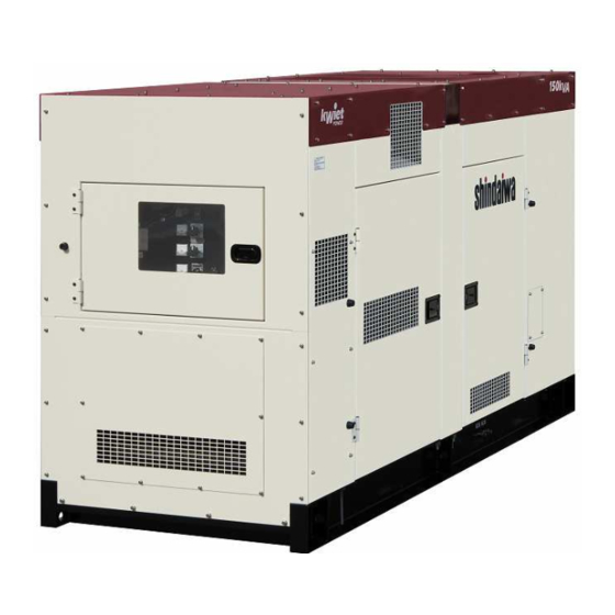
4. General 4.1 Appearance 4.2 Dimension Unit in the drawings below is shows by mm. -
Page 11: General Parts Description
5. General Parts Description 5.1 Equipment... -
Page 14: Main Parts And Feature
5.2 Main Parts and Feature (1) Unit Serial Number Provide both serial number of unit and engine to your local service shop for update parts and warranty information. (2) Engine Serial Number 5.3 Main Component Monitor Lamp Ampere Meter Selector Dial Volt Meter Selector Dial Feature: Light a monitor lamp Feature: Dial to select the... - Page 15 Control Panel (Internal View)
- Page 16 Engine Operation Switch Table (refer to No. 3 on page 11) Nomenclature Function Remarks This function is not available in this LOAD ADVANCE equipment. Decrease rpm in accordance with REGULATION the load to be put when the MODE switch turns to ON. Start: low idle mode THROTTLE Change idle mode.
- Page 17 Right Side Door Fuel Drain Plug Oil Drain Plug Feature: Drain the old fuel from the Feature: Drain the old oil from the oil fuel tank. tank. Left Side Door Terminal Rest Feature: Relay terminal block of the power output from the alternator.
- Page 18 3-Way Valve Feature: Valve to change fuel supply from a built-in or external tank. Note: Do not remove the plugs when fuel is supplied from a built-in tank. (when the 3-way valve positions at position A.) 3-Way Valve Position A Position A (to use a built-in fuel tank) Position the 3-way valve lever to UPWARD to use fuel from the external fuel tank.
-
Page 19: Component Layout
5.4 Component Layout... -
Page 26: Drain Plug And External Fuel Ports
5.5 Drain Plug and External Fuel Inlet Standard Accessory ① Owner’s Manual 1 copy ② Engine Instruction Manual 1 copy ③ Starter Key 1 set... - Page 27 WARNING DANGER OF ELECTRIC SHOCK DO NOT TOUCH OUTPUT TERMINALS DURING EQUIPMENT OPERATION! Do not touch the output terminal while the generator unit is operating since it can cause an electric shock. When it is necessary to touch the output terminals such as for load connections, make sure that the engine is not operating.
-
Page 28: Service Data
6. Service Data 6-1 Service Data Items Reference Value Note Armature DC500V Insulation winding 3MΩ or more Megger Tester Exciter field Approx. 20 sec. with coolant temperature Automatic Preheat time -15℃(5 °F) and approx. 1 sec. with coolant preheating system °F) temperature 30℃(86 Min. -
Page 29: Generator
6.2 Generator Main bearing Bolt Exciter armature Rotor Bolt Exciter field Thermo label Bearing cover Thermo label Rear bracket Bolt Exciter stator Bolt Armature Main stator Fan cover Stator Rotor... - Page 30 (1) Exciting Amperage Amperage fluctuates based upon the winding temperature. Following is for reference only. (Refer to page 39 in the service manual) Frequency/Rated Output Load Exciting Amperage (Measured) No load 0.57A 3-Phase 60Hz: 120 kW Full load( power factor=1.0) 1.04A (2) Resistance Value Nominal resistance of the winding is tolerated...
- Page 31 Article Method Condition to verify Criterion Connect “grounding terminal” - with output terminal “L1”. AC2400V (1 sec) - with output terminal “L2” Dielectric Voltage Tester Electric Current: 10mA - with output terminal “L3”. (Refer to page 36) - with initial excitation winding. (Coupler marked with “J”...
- Page 32 VOLT ADJ. Use screw locking glue (recommended ThreeBond 1401C) over the VRD and VRE after adjusted. Mode Output Voltage (V) Setting Time Frequency (Hz) Setting Time Loaded No Load below 288 below 2 sec. below 66 below 8 sec. (Transient Max.) No Load 240+/-3 60+/-0.2...
-
Page 33: Trouble Shooting Procedure
7. Trouble Shooting Procedures 7.1 Engine Generator Problem Suspected Cause Action Starter motor Battery output is weak Check battery for cracks or does not work Battery has deteriorated leaks/battery liquid/or Charge or speed is low. Battery terminal is OFF or loose Change battery Battery terminal is corroded Fix/Tighten terminal... - Page 34 Problem Suspected cause Action White smoke comes 1. Too much or too little oil to cylinder 1. Contact distributor to repair out from muffler (white smoke) 2. Drain water in water sediment, 2. Water is interfused in fuel line fuel filter or fuel tank 3.
-
Page 35: Avr Test Procedure
7.2 AVR Test Procedure ・ Do not adjust the volume while operating the generator unit. It may damage the AVR or affect result of the load. ・Before testing the resistance of the generator unit, remove the connectors from the AVR and Engine Control Module. - Page 36 1. Shut off engine. 2. Open the control panel and access the automatic voltage regulator (AVR). 3. Check the circuit breaker in AVR and push the circuit breaker button back to reset if it was tripped. Note: The circuit breaker in AVR trips due to overcurrent Circuit Breaker transmitted to the exciter.
- Page 37 4. Shut off engine and disconnect the CN1 connector. Caution: change voltage selector when engine run.
-
Page 38: Checking Output Voltage 480/277V
6. Close the terminal cover and turn main breaker ON, and measure voltage for “L1-L2”, “L2-L3” and “L1-L3” in the three phase terminals while engine run. Reading of the voltage should be 92V under no load. 1. Shut off engine. Set the voltage selector switch “480/277V”... -
Page 39: Checking Output Voltage 240/139V
1. Shut off engine. Set the voltage selector switch to “240/139V” position. Caution: DO NOT change the voltage selector switch when engine run. 2. Turn the main circuit breaker OFF. 3. Connect the leads to “L1-L2” terminals. 4. Close the terminal cover. 5. -
Page 40: Checking Output Voltage 240/120V
1. Shut off engine. Set the voltage selector switch to “240/120V” position. Caution: DO NOT change the voltage selector switch when engine run. 2. Turn the main circuit breaker OFF. Connect leads “L1-L2” terminals. 4. Close the terminal cover. 5. Turn the main breaker ON and check the output voltage. -
Page 41: Testing Main Circuit Breaker
1. Shut eff engine. Turn the main circuit breaker OFF. 2. Check the resistance by a ohmmeter between upper terminal and lower terminal Upper Terminal Lower Terminal The ohmmeter should display the symbol of infinity, ∞, or similar wording per an ohmmeter. 1. -
Page 42: Checking Generator Or Winding
7.7 Checking the Generator Winding 1. Shut off engine. Disconnect the lower wires from the terminal rest. 2. Check the resistance in the windings as per the table below. Note: Use a mill-ohmmeter with Kevin four wire probes. Terminal T1-T4 T7-N10 T2-T5 T8-N11... -
Page 43: Checking The Exciter Stator
7.8 Checking the Exciter Stator 1. Shut off engine. Disconnect the CN1 connector in the AVR. 2. Check the resistance between the terminals J and K. Note: Use an ohmmeter. Connector The ohmmeter should display 15.0 ohms ±10% at 70°in the Fahrenheit. -
Page 44: Checking The Adjusting Voltage Regulator
7.9 Check the Adjusting Voltage Regulator 1. Shut off engine. Disconnect the CN3 connector in the adjusting voltage regulator. 2. Turn the adjusting voltage regulator knob fully counter-clockwise. 3. Connect the lead to the terminal #1 and #2 (white/blue wire) in the CN3 connector as shown in the picture below. -
Page 45: Checking The Voltmeter
7.10 Checking the Voltmeter 1. Access the back of the control panel. 2. Start the engine. 3. Turn the main breaker ON. 4. Turn the voltmeter selector dial to “L1-L2”. 5. Check the output voltage of the “VS1” and “VS2” located the back of the voltmeter. -
Page 46: Checking The Voltmeter Selector Dial
7.11 Checking the Voltmeter Selector Dial 1. Set the voltmeter selector dial to “L1-L2”. 2. Check the output voltage of the “T1-T2” located in the volume of the voltmeter selector dial 3. Check the output voltage of “L1-L2” in the main terminal rest. -
Page 47: Checking The Current Transformer
7.12 Checking the Current Transformer (CT) 1. Shut engine. Connect the load (3-phase) to the unit. (cf. motor) 2. Start the engine. 3. Turn the main breaker ON. 4. Check the current of the wires “TT”, “TR” and “CTE” in the ammeter selector dial. Replace the CT1 if no amps were confirmed in “TR”... -
Page 48: Checking The Ammeter
7.13 Checking the Ammeter Note: Conduct the following checking after “Checking the Current Transformer (CT)” in the previous section, 7.12 with a satisfactory result confirmed. 1. Shut off engine. Connect the load (3-phase) to the unit. (cf. motor) 2. Start the engine. 3. -
Page 49: Resetting The Thermal Relay
7.14 Reset the Thermal Relay... -
Page 51: Testing Voltage Selector Switch
7.16 Checking the Voltage Selector Switch 1. Shut off engine. 2. Remove all leads from the voltage selector switch. 3. Check continuity of terminals in the voltage selector switch. Use ohmmeter. There should be continuity between the terminals as shown in the table below. -
Page 52: Abnormal Frequency Or Voltage Drop
7.17 Abnormal Frequency or Voltage Drop 1. Check engine rpm. Use the tachometer. RPM should be 1800±80 rpm. 2. Confirm all the switches in the engine control switch panel direct correct as shown in the picture below. RPM should significantly be higher or lower if all the toggle switches direct correctly. - Page 53 7.17 Abnormal Frequency or Voltage Drop (cont.) 3 Check the current in each phase. 4 Lower the load if current exceeds rated output shown in the specifications.
-
Page 54: Engine Won't Start
7.18 Engine Won’t Start 1. Check fuel level. 2. Check the fuel filter visually to see if it is dirty. 3. Check the air filter if it is plugged with dirt. 4. Disconnect the terminal from the battery and check voltage of each battery. Voltage should be 12 ~ 14 volts. - Page 55 7.18 Engine Won’t Start (cont.) 6. Access the starter relay located in the back of the control panel. 7. Disconnect “CN4” connector from the starter relay. 8. Turn the ignition switch to “START” and check the output voltage between the “red/white” and “blue/white” terminals in the “CN4”...
-
Page 56: Engine Stops Suddenly
Upper Limit Lower Limit 7.19 Engine Stops Suddenly Oil Gauge 1. Check engine oil and refill if the level is below the low level. Oil should be leveled between LOW and HIGH in the oil gauge. 2. Check coolant and refill if the level is below LOW in the sub tank. -
Page 57: Monitor Lamp Blinking
7-20 Monitor Lamp Blinking This unit is equipped with monitoring function and the monitoring lamp flashes when defect is detected. The EMPS III diagnostic equipment would be necessary if the engine control module and etc. in the electronic fuel injection system may be caused. Contact your local Isuzu dealer if the monitor lamp may flush and did not cure the problem. - Page 59 - Tier 3 Engine by Isuzu *ECM: Emission Control Module...
-
Page 60: Maintenance
8. Maintenance Daily Every Every Every Description check 250hrs 500hrs 1000hrs Engine Side ◯ Clean each parts / tightening ◯ Engine oil checks / add oil ◯ ◯ Engine oil and Oil Filter change time at 50 hrs) ◯ ◯ PCV Filter change time at 50 hrs) ◯... -
Page 61: Layout Of The Unit
8.1 Layout of the Unit Radiator Air Cleaner Generator Intercooler Electromagnetic Fuel Pump Main Fuel Filter Oil Filter Pre-Fuel Filter Fuel Drain Valve – Left Oil Drain Valve - Right... -
Page 62: Oil Change
8.2 Engine Oil Replacement... -
Page 63: Oil Filter Replacement
8.3 Oil Filter Replacement Oil Gauge Lower Limit Upper Limit... -
Page 67: Cleaning/Replacing The Fuel Filter
8.8 Cleaning/Replacing Fuel Filter... - Page 68 8.8 Cleaning/Replacing Fuel Filter (cont.) Wrench for Fuel Filter:...
-
Page 70: Tightening Torque
9. Tightening Torque 9.1 Specific Tightening Torque Torque Part to Allowance Nomenclature Size Reference tighten Nm(kgf/cm) Put a lubricant to Drain 68.7-88.2 Drain Plug~Socket O-ring and align Plug (fine pitch) (701-899) it into a groove. 49.1-58.8 Socket~Oil Pan Nipple ditto ditto (501-599) 1.0-1.4... -
Page 71: General Tightening Torque
Torque Part to Allowance Nomenclature Size Reference tighten Nm(kgf/cm) 54.2-63.9 Joint~Engine Joint G3/4 ditto (553-651) Attention to 107.9-127.4 Hose,14~Joint Hose, 14 G3/4 piping for inlet & (1101-1299) outlet. Attention to the Cleaner direction of the Air Cleaner Band air cleaner intake. -
Page 72: Wiring Diagram
10. Wiring Diagram... - Page 74 YAMABIKO CORPORATION 35 SHIN-UJIGAMI, KITA-HIROSHIMA-CHO, YAMAGATA-GUN, HIROSHIMA 731-1597 JAPAN Telephone: (81)826-72-5140 Fax: (81) 82-826-72-7004 www.yamabiko-corp.co.jp...
Need help?
Do you have a question about the DGK150D/EPA3 and is the answer not in the manual?
Questions and answers