Table of Contents
Advertisement
Quick Links
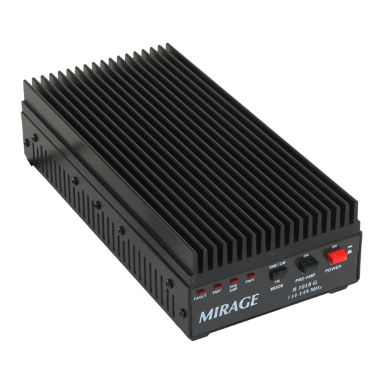
Mirage B 1018 G
This compact, rugged, VHF RF power amplifier greatly improves signal-quality and
range.
This unit contains a low-noise GAsFET receiving amplifier, a 160-watt power
amplifier, and associated control and protection circuitry.
This amplifier operates from any well-filtered direct-current 11-15 volt power source
capable of supplying 30 amperes under full-load. The power source must be either
negative grounded or totally ground independent.
Warning, never use this unit with:
1.) positive-ground supplies
2.) vehicles having positive-ground batteries
3.) power sources exceeding 16 volts
Always fuse power leads at the battery with 30-ampere fast-blow fuses.
This amplifier has the following important features:
1.) Automatic RF actuated transmit and receive switching or manual switching
2.) Active bias for greatly improved SSB linearity
3.) Low-noise GAsFET receive preamplifier
4.) True push-pull circuitry and clean RF layout for excellent stability
5.) Excess SWR and overdrive protection
6.) Remote control capabilities
1
Advertisement
Table of Contents

Related Manuals for Mirage Mirage B 1018 G


Summary of Contents for Mirage Mirage B 1018 G
- Page 1 Mirage B 1018 G This compact, rugged, VHF RF power amplifier greatly improves signal-quality and range. This unit contains a low-noise GAsFET receiving amplifier, a 160-watt power amplifier, and associated control and protection circuitry. This amplifier operates from any well-filtered direct-current 11-15 volt power source capable of supplying 30 amperes under full-load.
-
Page 2: Table Of Contents
Table of contents Quick Connect Important: Read this section first! Mounting Considerations Cooling and Temperature Power Wiring RF and Controls Cables Mobile Mounting Conderations Home or Fixed Installations Repeater Mounting Radio or Exciter Drive Level Duty Cycle T/R Control or “Keying” Wiring FM, CW and Non-Linear Modes Drive Power... -
Page 3: Quick Connect
0.0 QUICK CONNECT 1.) Mount or place the amplifier in a cool area. The best mounting position will place the long length of heatsink fins vertical. The amplifier must have sufficient cool air supply. Do not mount in confined or hot locations, or where exposed to moisture. -
Page 4: Mounting Considerations
Heatsink temperatures above 140°F indicate the need for additional cooling, such as re-mounting the amplifier in a cooler location or the addition of a small fan blowing on the heatsink. Mirage has a cooling kit, P/N FK-18. This kit includes a 12 Vdc fan and mounting bracket. -
Page 5: Rf And Controls Cables
To reduce fire hazards or the chance of equipment damage, the red lead must always be fused with a 30-ampere fuse at the battery. Some power supplies have internal current protection. Power supplies without current limiting must be protected by properly sized fuses located at the supply. -
Page 6: Mobile Mounting Conderations
The ANTENNA connector is a SO-239 (UHF Female). The design load impedance is 50-ohms, and any load with a VSWR under 2:1. The output cable must safely handle the full power of the amplifier, and must have good connections. Be sure connectors are installed and soldered properly, and the coaxial cables are of reasonably good quality. -
Page 7: Home Or Fixed Installations
The RF cables should not be excessively long, although they are not critical. 1.5 HOME OR FIXED INSTALLATIONS Mount the amplifier in any location that is cool, and has air circulation. It is best to mount this unit with the long length of the heatsink fins vertical. For extended duty, you may want to add a cooling fan. -
Page 8: Wiring
off when the RELAY line is pulled low (grounded). If the POWER switch is on, the internal transmitting relays will switch to the transmit mode. 2.4 WIRING The exciter can be connected to the amplifier with any type of good quality 50-ohm coaxial cable. Length and cable size is not important, except as it might add signal loss if the cable is extremely long. -
Page 9: Feedlines And Antennas
If possible, especially if cooling might be marginal and there is no external air blowing across the heatsink, mount the amplifier with heatsink fins vertical. This allows natural convection to circulate air. See section 1.0 for details. Warning, the safe maximum temperature of the heatsink is 140°F. If the heatsink feels too hot to hold, it is almost certainly too hot for safe operation. -
Page 10: Drive Power
At high power levels, three main problems limit linearity and cause splatter. All three problems are reduced or cured by turning the drive power down. 1.) Output-device current amplification (in this case transistors are used) is a problem. Transistors, unlike most vacuum tubes, show a gradual decrease in gain as drive level increases. -
Page 11: Duty Cycle
Maximum power output for good linearity is 110 watts PEP, as indicated on a properly working PEP-reading meter. In AM operation, carrier output power is normally 25% or more of the peak envelope power as indicated on a true peak-reading meter. Unmodulated carrier power should not exceed 25 watts; peak envelope power on AM should not exceed 100 watts or so. -
Page 12: Antennas And Feedlines
4.6 ANTENNAS AND FEEDLINES Any antenna and 50-ohm feedline can be used, providing it presents less than 2:1 SWR to this amplifier. Linearity and splatter will be better controlled if SWR is as low as possible, with a 1:1 SWR ratio (unity SWR) being ideal. Be sure to use proper lightning protection techniques when using this amplifier for home or fixed operation. -
Page 13: In Case Of Difficulties
receive system or internal to the receive system. Every effort was made to make the preamplifier in this unit immune to overload. The receiver may overload if signal levels from the preamplifier are stronger than the receiver can tolerate. In some cases, the preamplifier itself may be overloaded. If paging or other commercial transmitters suddenly appear in the receiver while using the preamplifier, try turning the preamplifier off. -
Page 14: Receives Ok, Does Not Amplify Transmit
Parts are available direct from Mirage, either by calling 662-323-8287; faxing 662-323-6551 or writing to Mirage, 300 Industrial Park Road, Starkville, MS 39759. When faxing or writing, be sure to include a phone number you can be reach at during Mirage business hours. -
Page 15: Schematic
8.0 SCHEMATIC...