Table of Contents
Advertisement
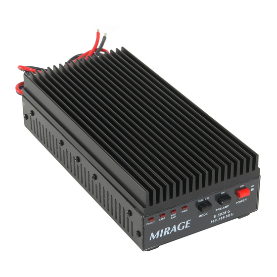
Mirage B 5018 G
This compact, rugged, VHF RF power amplifier greatly improves signal-quality and
range.
This unit contains a low-noise GAsFET receiving amplifier, a 160-watt power
amplifier, and associated control and protection circuitry.
This amplifier operates from any well-filtered direct-current 11-15 volt power source
capable of supplying 30 amperes under full-load. The power source must be either
negative grounded or totally ground independent.
Warning, never use this unit with:
1.) positive-ground supplies
2.) vehicles having positive-ground batteries
3.) power sources exceeding 16 volts
Always fuse power leads at the battery with 30-ampere fast-blow fuses.
This amplifier has the following important features:
1.) Automatic RF actuated transmit and receive switching or manual switching
2.) Active bias for greatly improved SSB linearity
3.) Low-noise GAsFET receive preamplifier
4.) True push-pull circuitry and clean RF layout for excellent stability
5.) Excess SWR and overdrive protection
6.) Remote control capabilities
1
Advertisement
Table of Contents

Related Manuals for Mirage B 5018 G


Summary of Contents for Mirage B 5018 G
- Page 1 Mirage B 5018 G This compact, rugged, VHF RF power amplifier greatly improves signal-quality and range. This unit contains a low-noise GAsFET receiving amplifier, a 160-watt power amplifier, and associated control and protection circuitry. This amplifier operates from any well-filtered direct-current 11-15 volt power source capable of supplying 30 amperes under full-load.
-
Page 2: Table Of Contents
Table of contents Quick Connect Important: Read this section first! Mounting Considerations Cooling and Temperature Power Wiring RF and Controls Cables Mobile Mounting Conderations Home or Fixed Installations Repeater Mounting Radio or Exciter Drive Level Duty Cycle T/R Control or “Keying” Wiring FM, CW and Non-Linear Modes Drive Power... -
Page 3: Quick Connect
0.0 QUICK CONNECT 1.) Mount or place the amplifier in a cool area. The best mounting position will place the long length of heatsink fins vertical. The amplifier must have sufficient cool air supply. Do not mount in confined or hot locations, or where exposed to moisture. -
Page 4: Mounting Considerations
Heatsink temperatures above 140°F indicate the need for additional cooling, such as re-mounting the amplifier in a cooler location or the addition of a small fan blowing on the heatsink. Mirage has a cooling kit, P/N FK-18. This kit includes a 12 Vdc fan and mounting bracket. -
Page 5: Rf And Controls Cables
To reduce fire hazards or the chance of equipment damage, the red lead must always be fused with a 30-ampere fuse at the battery. Some power supplies have internal current protection. Power supplies without current limiting must be protected by properly sized fuses located at the supply. -
Page 6: Mobile Mounting Conderations
The ANTENNA connector is a SO-239 (UHF Female). The design load impedance is 50-ohms, and any load with a VSWR under 2:1. The output cable must safely handle the full power of the amplifier, and must have good connections. Be sure connectors are installed and soldered properly, and the coaxial cables are of reasonably good quality. -
Page 7: Home Or Fixed Installations
During repeater operation, output power must be reduced to 50 watts (approximately 6 watts of drive power). The cooling system must be augmented with forced air using the Mirage FK-18 cooling kit or a similar product. -
Page 8: Duty Cycle
2.2 DUTY CYCLE The duty cycle of this unit is primarily limited by heatsink temperature. The more power output and hotter the ambient temperature, the more important cooling becomes. See section 1.1 2.3 T/R CONTROL OR “KEYING” This unit contains an internal RF sensing system. This system will automatically disconnect the receiving pre-amplifier (if being used). -
Page 9: Duty Cycle Cw And Fm
3.2 DUTY-CYCLE CW AND FM The duty-cycle is set by ambient temperature, mounting position, operating power, and airflow. Temperature and mounting concerns are detailed in section 1.0. Driving-power concerns are detailed in section 2.0 The maximum amplifier output power on CW, FM and FSK is 160 watts ICAS. At the maximum power output of 160 watts, this amplifier will normally provide a 33% long-term duty cycle without overheating. -
Page 10: Splatter And Distortion
Peak-envelope output power should not exceed 100 watts when measured on an accurate peak reading meter. 4.1 SPLATTER AND DISTORTION At low power levels, amplifier gain is affected by bias settings. If bias is set too low, turning drive power down can actually make the ratio of distortion-to-signal worse (not better)! This amplifier has an active-bias system, which forces the bias voltage to a fixed level. -
Page 11: Duty Cycle
Power should be measured on a true peak-reading meter. Many manufacturers market meters that are not actual peak-reading meters, even though they call the meters peak-reading. If you have a meter like that, you will find it impossible to properly determine drive settings on SSB using the meter. If you do not have a true peak-reading meter, either an oscilloscope or off-the-air reports can be used to determine if you are driving the amplifier too hard. -
Page 12: Power Output
4.5 POWER OUTPUT The maximum power output for clean linear SSB service is 110 watts PEP. Antenna SWR should be as low as possible. The 13.8-volt 30-ampere power source must not have hum or ripple. The voltage should have less than 0.2 volts sag under full-load for best linearity. 4.6 ANTENNAS AND FEEDLINES Any antenna and 50-ohm feedline can be used, providing it presents less than 2:1 SWR to this amplifier. -
Page 13: Intermodulation (Imd) Products
5.2 INTERMODULATION (IMD) PRODUCTS IMD is the result of signals mixing in amplifiers or other less-than-perfect devices. IMD results in signals appearing on entirely new frequencies. This problem can occur either external to the receive system or internal to the receive system. Every effort was made to make the preamplifier in this unit immune to overload. -
Page 14: Transmit Ok, Does Not Amplify Receive
Parts are available direct from Mirage, either by calling 662-323-8287; faxing 662-323-6551 or writing to Mirage, 300 Industrial Park Road, Starkville, MS 39759. When faxing or writing, be sure to include a phone number you can be reach at during Mirage business hours. -
Page 15: Notes
Please have a credit card number available over the phone (do NOT include credit card information in the mail), or prepay the order with a check after calling for prices. Part numbers are listed after the schematic. Be sure you have the full part description, the model and serial number (if used on this product), and the part number. -
Page 16: Schematic
8.0 SCHEMATIC...
Need help?
Do you have a question about the B 5018 G and is the answer not in the manual?
Questions and answers