Table of Contents
Advertisement
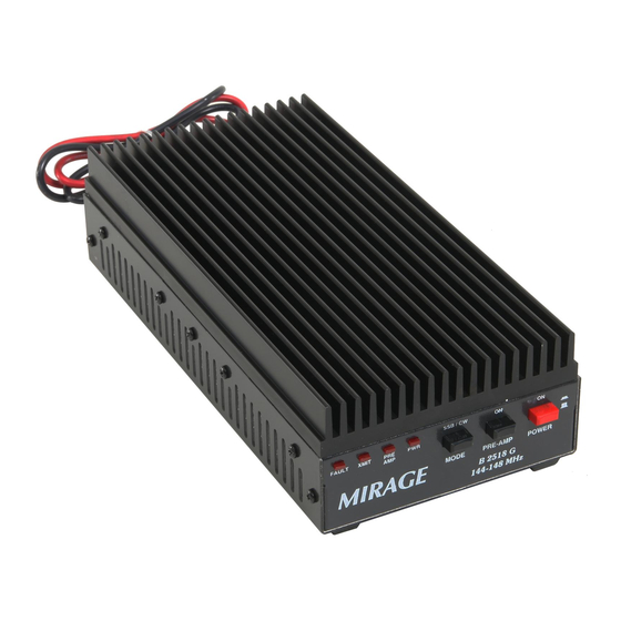
This compact, rugged, VHF RF power amplifier greatly improves signal-
quality and range. This unit contains a low-noise GAsFET receiving
amplifier, a 160-watt power amplifier, and associated control and
protection circuitry.
This amplifier operates from any well-filtered direct-current 11-15 volt
power source capable of supplying 30 amperes under full-load. The
power source must be either negative grounded or totally ground
independent.
Warning,
never use this unit with:
1.)
positive-ground supplies
2.)
vehicles having positive-ground batteries
3.)
power sources exceeding 16 volts
Always fuse power leads at the battery with 30-ampere fast-
blow fuses.
This amplifier has the following important features:
1.)
Automatic RF actuated transmit and receive switching or manual
switching
2.)
Active bias for greatly improved SSB linearity
3.)
Low-noise GAsFET receive preamplifier
4.)
True push-pull circuitry and clean RF layout for excellent stability
5.)
Excess SWR and overdrive protection
6.)
Remote control capabilities
Mirage B 2518 G
Advertisement
Table of Contents

Related Manuals for Mirage B 2518 G


Summary of Contents for Mirage B 2518 G
- Page 1 Mirage B 2518 G This compact, rugged, VHF RF power amplifier greatly improves signal- quality and range. This unit contains a low-noise GAsFET receiving amplifier, a 160-watt power amplifier, and associated control and protection circuitry. This amplifier operates from any well-filtered direct-current 11-15 volt power source capable of supplying 30 amperes under full-load.
-
Page 2: Table Of Contents
Table of contents QUICK CONNECT Read this section first no matter what! Mounting Considerations Cooling and Temperature (Mobile or Fixed Location) Mobile mounting Fixed or base mounting Repeater operation Radio or exciter Power level T/R control or “keying” interface RF wiring connections FM and other Non-linear Operation Drive power Duty cycle... -
Page 3: Quick Connect
0.0 Quick Connect 1.) Mount or place the amplifier in a cool area. The best mounting position will place the long length of heatsink fins vertical. The amplifier must have sufficient cool air supply. Do not mount in confined or hot locations, or where exposed to moisture. -
Page 4: Mounting Considerations
Mirage has a cooling kit, P/N FK- 18. This kit includes a 12 Vdc fan and mounting bracket. - Page 5 NOTE: As temperature in the mounting area increases, especially if air is not moving, cooling becomes less effective and the amplifier will “run hotter”. If cooling is a problem, the largest change will come from forcing air over the heatsink with a small fan. The heatsink in this amplifier is sized for ICAS operation at 160 watts carrier output with a 33% long-term duty cycle.
- Page 6 the battery and amplifier. NEVER omit this fuse, no matter how safe you think it Suitable fuses and holders are generally available from electronics, car stereo, and automotive parts stores. This device requires a 30-ampere fuse. The following chart gives the approximate peak voltage drop in volts per foot of a single supply wire with 30 amperes of current.
-
Page 7: Mobile Mounting
The current from this jack is less than 100 mA, and the open circuit voltage is less than 15 volts. There are no damaging back-pulses from this jack, it is fully buffered. Never apply voltage to this jack. 1.4 Mobile Mounting Considerations a.) Location Do not locate this amplifier in excessively warm locations, near heater vents, or in unventilated areas with ambient temperatures exceeding 120 degrees... -
Page 8: Radio Or Exciter
During repeater operation, output power must be reduced to 50 watts (approximately 3 watts of drive power). The cooling system must be augmented with forced air using the Mirage FK-18 cooling kit or a similar product. It is important to use good installation techniques. -
Page 9: Drive Power
2.3 T/R Control or “Keying” This unit contains an internal RF sensing system. This system will automatically disconnect the receiving pre-amplifier (if being used). It also places the unit in a transmit-mode when the POWER switch is ON. The rear-panel female phono (RCA) jack labeled RELAY can be used to manually force this unit to switch into a transmit mode. -
Page 10: Feedlines And Antennas
33% long-term duty cycle without overheating. Do not exceed 5 minutes total accumulated transmitting time without ten minutes of total accumulated resting time. This is a rough guideline; actual duty-cycle limitations depend on many factors. If possible, especially if cooling might be marginal and there is no external air blowing across the heatsink, mount the amplifier with heatsink fins vertical. -
Page 11: Drive Power
4.1 Splatter and Distortion At low power levels, amplifier gain is affected by bias settings. If bias is set too low, turning drive power down can actually make the ratio of distortion-to-signal worse (not better)! This amplifier has an active-bias system, which forces the bias voltage to a fixed level. -
Page 12: Duty Cycle
many factors, including the operator’s voice. Pushing up the drive power to “see” a certain output power on a meter that is NOT a true peak-reading meter is a mistake. Power should be measured on a true peak-reading meter. Many manufacturers market meters that are not actual peak-reading meters, even though they call the meters peak-reading. -
Page 13: T/R Control Or Switching
4.4 T/R Control or Switching This amplifier has an internal RF sensing system that turns off the pre-amplifier and places it in the transmit mode. A front-panel MODE switch activates an internal hang-delay timer for SSB (or CW) operation. This hang-time allows the relays to remain energized without input power for a few seconds. -
Page 14: Intermodulation Products
A lower noise-figure amplifier is seldom (if ever) necessary for terrestrial communications. Since this preamplifier will put almost any system well into ambient noise, no further improvement in sensitivity will result from more gain or lower noise figure. 5.2 Intermodulation (IMD) Products IMD is the result of signals mixing in amplifiers or other less-than-perfect devices. -
Page 15: Technical Assistance
6.2 Nothing lights or seems to work a.) Check the power wiring and fuses. The amplifier has an internal fuse also. b.) Read section 1.2 6.3 Transmits OK, does not amplify receive a.) If this unit fails transmits OK, but fails to make a difference on receiving weak signals, and the Preamp light illuminates, it may have a defective preamplifier. -
Page 16: Ordering Parts
6.8 Ordering Parts Parts are available direct from Mirage, either by calling xxxx or writing to xxxxx. Please have a credit card number available over the phone (do NOT include credit card information in the mail), or prepay the order with a check after calling for prices.
Need help?
Do you have a question about the B 2518 G and is the answer not in the manual?
Questions and answers