Lectrosonics WM Instruction Manual
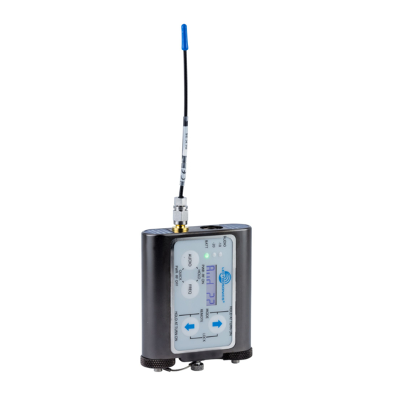
Watertight transmitter and remote controls
Hide thumbs
Also See for WM:
- Quick start manual (9 pages) ,
- Quick start manual (13 pages) ,
- Quick start manual (13 pages)
Table of Contents
Troubleshooting

Related Manuals for Lectrosonics WM


Summary of Contents for Lectrosonics WM
- Page 1 INSTRUCTION MANUAL Watertight Transmitter and Remote Controls With Digital Hybrid Wireless Technology ® US Patent 7,225,135 Fill in for your records: Serial Number: Purchase Date: Rio Rancho, NM, USA www.lectrosonics.com...
- Page 2 LECTROSONICS, INC.
-
Page 3: Table Of Contents
Watertight Transmitter Introduction Table of Contents The WM transmitter is designed to resist damage when Introduction..................3 General Technical Description............4 used in wet or dusty conditions and also offer a compre- Servo Bias Input................4 hensive feature set that makes it equally at home in film No Pre-Emphasis/De-Emphasis............4... -
Page 4: General Technical Description
The limiter recovers quickly from brief transients, with pandor and its artifacts. no audible side effects, and also recovers slowly from sustained high levels to keep audio distortion low while preserving short term dynamics. Regulator Variable 1.8 - 4v LECTROSONICS, INC. -
Page 5: Signal Encoding And Pilot Tone
Lectrosonics Output Isolator 200 Series, Lectrosonics 100 Series, IFB and certain The RF output circuit includes a magnetically polarized non-Lectrosonics receivers. Contact the Lectrosonics ferrite called an isolator that suppresses IM (inter- sales department for more information about non-Lec- modulation) that can take place in the final amplifier. -
Page 6: Controls And Functions
The PWR LED glows green when the battery is good. lent Lectrosonics Frequency Switch Setting. This but- The color changes to red when there is about 30 ton is also used with the AUDIO button to enter standby minutes of operation left with the recommended lithium mode and to power the transmitter on or off. -
Page 7: Battery Compartments
The recess in the opening retains the O-ring when the plug is tight- ened. The Lectrosonics M152WP lavaliere microphone is supplied with the WP plug already installed. Other micro- phones can also be terminated with this plug by following the instructions included with the WP connector kits. -
Page 8: Operating Instructions
Standby Mode In addition to its native Digital Hybrid mode, the trans- Quickly press both AUDIO mitter will operate with Lectrosonics 100 Series, 200 and FREQ buttons to enter Series and IFB receivers, as well as several analog the “standby” mode. In this receivers from other manufacturers. -
Page 9: Audio Lf Roll-Off And Gain
Normally, the receiver is used to find a clear operat- Use the UP and DOWN arrows to select the desired ing frequency. All Lectrosonics Digital Hybrid Wireless output power. receivers provide a scanning function to quickly and... -
Page 10: Frequency Selection
-20 LED -10 LED The hexadecimal numbering system is unique to Less than -20 dB Lectrosonics where two alphanumeric characters cor- -20 dB to -10 dB Green respond to the left and right switch settings on earlier analog transmitters that had mechanical rotary switch-... -
Page 11: Remote Control Enable/Disable And Configuring Power Restore
Watertight Transmitter unlock a locked transmitter are to remove the battery DIO and FREQ buttons after the batteries have been or unlock it via the RM remote control. replaced. When this function is turned off, the AUDIO and FREQ Remote Control Enable/Disable and buttons need to be held in for the completion of the Configuring Power Restore count to turn the unit back on for normal operation. -
Page 12: Optional Rm Remote Control
A single AA Lithium battery will operate the RM for up to several years. Unscrew the knurled knob for access to the battery compartment. LECTROSONICS, INC. -
Page 13: Operating Notes
RM Quick Reference A lower cost alternative to the RM, this model provides Power On/Off AUDIO+FREQ remote control of: Set WM audio level Aud page (via AUDIO) • Sleep/Unsleep Sleep or Wake SMV SLEEP/unSLP page (via AUDIO) •... -
Page 14: Lectrorm
Please be aware this app is not a Lectrosonics product. It is privately owned and operated by New Endian LLC, www.newendian.com. The iPhone version keeps each available setting on a separate page with the list of options for that setting. -
Page 15: Troubleshooting
Watertight Transmitter Troubleshooting Before going through the following chart, be sure that you have a good battery in the transmitter. It is important that you follow these steps in the sequence listed. SYMPTOM POSSIBLE CAUSE TRANSMITTER PWR LED OFF 1) Battery is inserted backwards or dead. 2) Transmitter not powered up. -
Page 16: Rm Troubleshooting
FREQUENCY CHANGES, BUT NOT TO DESIRED FREQUENCY 1) RM set on different block than transmitter in question. RM uses hex code to set frequency - set RM to proper frequency block, or use hex code method to change frequency. LECTROSONICS, INC. -
Page 17: Accessories And Replacement Parts
Model WMBCSL spring loaded belt clip. Includes hard- ware kit shown below. Replacement O-rings Model ORINGKIT/WM Includes replacement O-rings for battery caps and microphone plug with WM style connector, and petroleum jelly pouch. Wire Belt Clip Model WMBCWIRE includes hardware kit shown below. -
Page 18: Antenna Length By Block
614.400 - 639.900 Yellow 4.01” 101.9 mm 640.000 - 665.500 Green 3.82” 97.0 mm ACTUAL SIZE 665.600 - 691.100 Blue 3.62” 92.0 mm Check the scale of your print out. This rectangle should be 6 inches (152.4 mm) wide. LECTROSONICS, INC. -
Page 19: Desiccant Battery Caps
You must still be careful to keep mois- O-rings may need a tiny dab of petroleum jelly (Vase- ture out of the WM by opening it only in dry or shel- line) to replace the lubricant that may migrate in the tered areas and by making sure the battery surfaces heat. -
Page 20: Re-Conditioning (Drying Out) The Caps And Desiccant Beads
220 degrees (F) will dry the doors and desiccant, but it will not disturb any light lubricant (like the Vaseline petroleum provided with the WM) that is on the O-ring seals. While the cap assembly is apart and the beads re- moved, the parts can be cleaned to remove dust and corrosion. -
Page 21: Specifications
Watertight Transmitter Specifications Operating frequencies: Block 470 470.100 - 495.600 Block 23 588.800 - 607.900 614.100 - 614.300 Block 19 486.400 - 511.900 Block 24 614.400 - 639.900 Block 20 512.000 - 537.500 Block 25 640.000 - 665.500 Block 21 537.600 - 563.100 Block 26 665.600 - 691.100... - Page 22 The FCC requires that the following statements be The FCC requires that the following statement be included in this manual for the WM transmitter: included in this manual for the RM: For body worn operation, this transmitter models has This device complies with Part 15 of the FCC Rules.
-
Page 23: Service And Repair
There are no adjustments inside that will make a malfunctioning unit start working. LECTROSONICS’ Service Department is equipped and staffed to quickly repair your equipment. In warranty repairs are made at no charge in accordance with the terms of the warranty. Out-of-warranty repairs are charged at a mod- est flat rate plus parts and shipping. -
Page 24: Limited One Year Warranty
This warranty does not apply to used or demonstrator equipment. Should any defect develop, Lectrosonics, Inc. will, at our option, repair or replace any defective parts without charge for either parts or labor. If Lectrosonics, Inc. cannot correct the defect in your equipment, it will be replaced at no charge with a similar new item.
Need help?
Do you have a question about the WM and is the answer not in the manual?
Questions and answers