Table of Contents
Advertisement
Quick Links
Advertisement
Table of Contents

Related Manuals for Jet JTM-1254VS


Summary of Contents for Jet JTM-1254VS
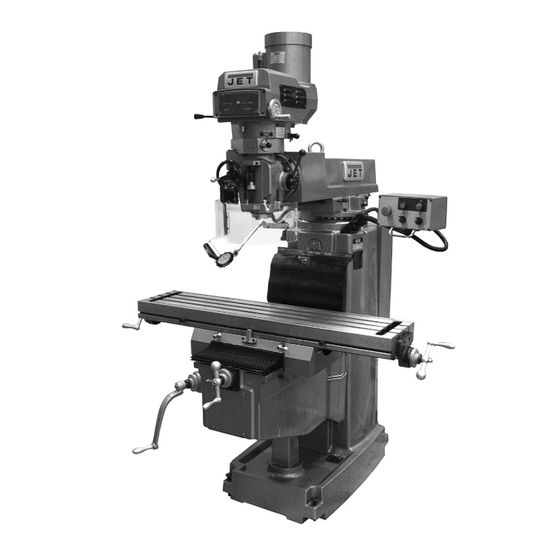
- Page 1 This .pdf document is bookmarked Operating Instructions and Parts Manual Variable Speed Turret Mill Models JTM-1254VS and JTM-1254RVS JTM-1254VS shown 427 New Sanford Road LaVergne, Tennessee 37086 Part No. M-690025 Ph.: 800-274-6848 Edition 2 11/2016 www.jettools.com Copyright © 2016 JET...
-
Page 2: Important Safety Instructions
Do not use this turret mill for other than its 17. Do not use power tools in damp/wet locations intended use. If used for other purposes, JET or other dangerous environments. Provide for disclaims any real or implied warranty and holds... -
Page 3: About This Manual
If there are questions or comments, please contact your local supplier or JET. JET can also be reached at our web site: www.jettools.com. -
Page 4: Table Of Contents
3.0 Table of contents ............................4 4.0 Specifications ..............................6 4.1 Machine dimensions – JTM-1254VS and JTM-1254RVS ................7 4.2 Overview and terminology – JTM-1254VS and JTM-1254RVS ..............8 5.0 Set-up and assembly ............................. 9 5.1 Contents of shipping container ........................9 5.2 Preparing the mill for service ........................ - Page 5 12.8.1 JTM-1254VS/RVS Control Box Assembly – Exploded View .............. 45 12.8.2 JTM-1254VS/RVS Control Box Assembly – Parts List ............... 45 12.9.1 JTM-1254VS/RVS Electrical Box – Exploded View ................46 12.9.2 JTM-1254VS/RVS Electrical Box – Parts List ..................46 12.10.1 JTM-1254VS/RVS Coolant Pump (Optional) – Exploded View ............47 12.11.1 JTM-1254VS/RVS Work Lamp –...
-
Page 6: Specifications
The specifications in this manual were current at time of publication, but because of our policy of continuous improvement, JET reserves the right to change specifications at any time and without prior notice, without incurring obligations. -
Page 7: Machine Dimensions - Jtm-1254Vs And Jtm-1254Rvs
4.1 Machine dimensions – JTM-1254VS and JTM-1254RVS Figure 4-1: Installation Diagram... -
Page 8: Overview And Terminology - Jtm-1254Vs And Jtm-1254Rvs
4.2 Overview and terminology – JTM-1254VS and JTM-1254RVS Figure 4-2: Overview... -
Page 9: Set-Up And Assembly
17/19mm Box Wrench * Read and understand the entire Cross Point Screw Driver #2 * contents of this manual before attempting set- Flat Blade Screw Driver #2 * up or operation. Failure to comply may cause Oil Can * serious injury. Elevating Crank Handle Handwheel Coarse Feed Handle... -
Page 10: Electrical Connections
6.3 Voltage conversion 15. Install table longitudinal and cross-feed cranks on their respective shafts using the nuts on the The JTM-1254VS and JTM-1254RVS have been shafts to secure the cranks. pre-wired for 230 volt operation. To change from 230 to 460 volt operation: 16. -
Page 11: Lubrication
Change incoming lead on transformer from Refer to section 10.0 for additional lubricating 230V to 460V terminal (Figure 6-2). instructions, before operating machine. Adjust overload relay setting to appropriate amperage (Figure 6-2). Figure 7-1 8.0 Operating instructions 8.1 Operating controls The position of mill head can be set up to accommodate the workpiece being machined. -
Page 12: Control Positions For Milling And Drilling Operations
B – Coolant switch: Turns on and off coolant pump. The spindle direction switch controls a three-phase motor. The motor can be switched from forward to C – Power on button: Turns on power to machine. reverse and back with the motor running, and will reverse direction when the switch setting is D –... -
Page 13: Spindle Brake
8.4 Spindle brake Do not move Quill Power Feed Lever unless motor is at complete The spindle brake lever (Figure 8-2) is used to stop stop (spindle off – D, Figure 8-1). When changing spindle immediately instead of allowing it to coast to a lever position, do it gently. -
Page 14: Feed Trip Cam Lever
8.8 Feed trip cam lever The Feed Trip Cam Lever (A, Figure 8-6) is located behind Manual Fine Feed Handwheel (B). It engages the overload clutch on pinion shaft when positioned to the left. The Feed Trip Cam Lever stays engaged until Quill Stop (G, Figure 8-8) contacts Micrometer Adjusting Nut (F, Figure 8-8) forcing it to drop out automatically, or until it is released manually by pushing lever to the right. -
Page 15: Fine Feed Handwheel
8.14 Fine feed handwheel When the controls are set for the Fine feed using handwheel position (see Table 2), the Fine Feed Handwheel (B, Figure 8-6) can be used for manual fine feed control in either upward or downward direction of quill. -
Page 16: Clamping Workpiece To Table
Tighten draw bar firmly using provided wrench. Turn draw bar. The tool is now ready for use. 8.17 Clamping workpiece to table The worktable has 5/8-inch T-slots for clamping workpiece to table. Set motor switch to neutral (stop) position. Place workpiece on table. Clamp workpiece using T-slot clamps, studs, and step blocks as required (Figure 8-11). -
Page 17: Positioning Ram
9.2.2 Positioning ram on turret Make sure machine base is secured to floor before repositioning ram. The center of gravity can shift enough to cause machine to tip over, resulting in serious injury to operator and damage to machine. Loosen four turret lock bolts (E, Figure 9-3) that clamp the ram to the top of the base. -
Page 18: Power Feed Trip Lever Mechanism
9.3.3 Table gib adjustment feed lever correctly engages and disengages when driven by drive motor. Table gib adjustment screws (C, Figure 9-4) are beneath table. Tighten screws until slight drag is felt when turning 9.5 Table lead screw backlash longitudinal table cranks. adjustment Refer to Figure 9-6. - Page 19 Figure 9-6...
-
Page 20: User-Maintenance
10.0 User-maintenance Before any intervention on the machine, disconnect it from electrical supply by pulling out plug or switching off main switch. Failure to comply may cause serious injury. 10.1 Lubrication The milling machine is equipped with an automatic lubrication system. The system lubricates lead screws and ways. Oil cups and grease fittings on mill head provide lubrication for spindle bearings and back gear mechanism. -
Page 21: Periodic Maintenance Requirements
Non-proprietary parts, such as fasteners, can be found at local hardware stores, or may be ordered from JET. Some parts are shown for reference only, and may not be available individually. -
Page 22: Jtm-1254Vs Upper Head Assembly - Exploded View
12.1.1 JTM-1254VS Upper Head Assembly – Exploded View... -
Page 23: Jtm-1254Vs Upper Head Assembly - Parts List
12.1.2 JTM-1254VS Upper Head Assembly – Parts List Index No Part No Description Size 1 ....JTM1254VS-A01 ..Upper Pulley Housing ..................1 2 ....JTM1254VS-A02 ..Motor Disc - Upper..................1 3 ....TS-1523011 ....Set Screw ..............M6x6L ......4 4 .... - Page 24 Index No Part No Description Size 62 ....JTM1254VS-A62 ..Timing Wheel ....................1 63 ....JTM1254VS-A63 ..Timing Belt ..................... 1 64 ....JTM1254VS-A64 ..Bearing Seat ....................1 65 ....BB-6203ZZ ....Ball Bearing ............. 6203ZZ ......2 66 ....
- Page 25 133 .... LM000005 ....Speed Range Label ..................1 134 .... JTM949EVS-A91 ..Push Plate ..................... 1 135 .... JTM949EVS-A92 ..Limit Switch....................1 136 .... LM000182 ....Motor Label ....................1 137 .... JET-165 ..... JET Logo ..............165x68 mm ....1...
-
Page 26: Jtm-1254Rvs (R8) Upper Head Assembly - Exploded View
12.2.1 JTM-1254RVS (R8) Upper Head Assembly – Exploded View... -
Page 27: Jtm-1254Rvs (R8) Upper Head Assembly - Parts List
12.2.2 JTM-1254RVS (R8) Upper Head Assembly – Parts List Index No Part No Description Size 1 ....JTM949EVS-A77 ..Upper Pulley Housing ..................1 2 ....JTM1254RVS-A02 ..Motor Disc - Upper..................1 3 ....TS-1523011 ....Set Screw ..............M6x6L ......4 4 .... - Page 28 Index No Part No Description Size 62 ....JTM949EVS-A34 ..Timing Pulley ....................1 63 ....JTM949EVS-A32 ..Timing Belt ............... 225L100 ......1 64 ....JTM949EVS-A19 ..Ball Bearing Bracket ..................1 65 ....BB-6203ZZ ....Ball Bearing ............. 6203ZZ ......2 66 ....
- Page 29 133 .... LM000005 ....Speed Range Label ..................1 134 .... JTM949EVS-A91 ..Push Plate ..................... 1 135 .... JTM949EVS-A92 ..Limit Switch....................1 136 .... LM000182 ....Motor Label ....................1 137 .... JET-165 ..... JET Logo ..............165x68 mm ....1...
-
Page 30: Jtm-1254Vs Lower Head Assembly - Exploded View
12.3.1 JTM-1254VS Lower Head Assembly – Exploded View... -
Page 31: Jtm-1254Vs Lower Head Assembly - Parts List
12.3.2 JTM-1254VS Lower Head Assembly – Parts List Index No Part No Description Size 1 ....TS-1502031 ....Hex Socket Cap Screw ..........M5x12L ......6 2 ....JTM949EVS-B02 ..Flat Washer ............. Ø5 ......... 1 3 ....JTM1254VS-B03 ..Feed Gear...................... 1 4 .... - Page 32 Index No Part No Description Size 49 ....JTM1254VS-B49 ..Overload Clutch Lockout ................1 49-1 ... TS-2276081 ....Set Screw ..............M6x8L ......1 49-2 ... JTM1254VS-B49-2 ..Lock Block ..................... 1 50 ....JTM1254VS-B50 ..Clutch Ring ....................1 51 ....
- Page 33 Index No Part No Description Size 98 ....JTM1254VS-B98 ..Quill Pinion Shaft ................... 1 ....JTM1254VS-B98A ..Quill Pinion Shaft Assembly (includes #98,98-2) ........... 1 98-1 ... KF2R5525 ....Key................5x5x25L ......1 98-2 ... JTM1254VS-B98-2 ..T type Pin....................... 1 99 ....
-
Page 34: Jtm-1254Rvs (R8) Lower Head Assembly - Exploded View
12.4.1 JTM-1254RVS (R8) Lower Head Assembly – Exploded View... -
Page 35: Jtm-1254Rvs (R8) Lower Head Assembly - Parts List
12.4.2 JTM-1254RVS (R8) Lower Head Assembly – Parts List Index No Part No Description Size 1 ....TS-1502031 ....Hex Socket Cap Screw ..........M5x12 ......6 2 ....JTM949EVS-B02 ..Flat Washer ............. Ø5 ......... 1 3 ....JTM949EVS-B03 ..Feed Gear...................... 1 4 .... - Page 36 Index No Part No Description Size 73 ....TS-1502081 ....Hex Socket Cap Screw ..........M5x35 ......2 74 ....JTM949EVS-B74 ..Clutch Ring Pin ....................2 75 ....JTM949EVS-B75 ..Clutch Ring ....................1 76 ....5302731 ....Socket Set Screw ............ M8x6 ......2 77 ....
- Page 37 Index No Part No Description Size 131 .... BB-6206ZZ ....Ball Bearing ............. 6206ZZ ......1 132 .... JTM949EVS-B132 ..Hub Sleeve ....................1 133 .... JTM949EVS-B133 ..Nose Piece ....................1 134 .... JTM949EVS-B134 ..Spindle Shield ....................1 135 ....
-
Page 38: Jtm-1254Vs Base Machine - Exploded View
12.5.1 JTM-1254VS Base Machine – Exploded View... -
Page 39: Jtm-1254Vs Base Machine - Parts List
12.5.2 JTM-1254VS Base Machine – Parts List Index No Part No Description Size 1 ....JTM1050EVS-C98 ..Lifting Ring ............... M30 ....... 1 2 ....JTM1254VS-C02 ..Ram ....................... 1 3 ....JTM949EVS-C02 ..Worm Gear ....................1 3-1 ..... - Page 40 107 .... TS-1504031 ....Hex Socket Cap Screw ..........M6x12L ......4 108 .... TS-1550041 ....Flat Washer ............. Ø6 ......... 4 109 .... LM000183 ....ID/Warning Label, JTM-1254VS ..............1 110 .... JET-254 ..... JET Logo ..............254x105 mm ....2...
-
Page 41: Jtm-1254Rvs (R8) Base Machine - Exploded View
12.6.1 JTM-1254RVS (R8) Base Machine – Exploded View... -
Page 42: Jtm-1254Rvs (R8) Base Machine - Parts List
12.6.2 JTM-1254RVS (R8) Base Machine – Parts List Index No Part No Description Size 1 ....JTM1050EVS2-C29A Lifting Ring ............... M20 ....... 1 2 ....JTM1050EVS2-30 ..Ram ....................... 1 3 ....JTM949EVS-C02 ..Worm Gear ....................1 3-1 ..... - Page 43 108 .... TS-1550041 ....Flat Washer ............. Ø6 ......... 4 109 .... LM000243 ....ID/Warning Label, JTM-1254RVS ..............1 110 .... JET-254 ..... JET Logo ..............254x105 mm ....2 ....JTM1254RVS-TB ..Tool Box Kit Complete (not shown) ............... 1...
-
Page 44: Jtm-1254Vs/Rvs Table Assembly - Exploded View
12.7.1 JTM-1254VS/RVS Table Assembly – Exploded View 12.7.2 JTM-1254VS/RVS Table Assembly – Parts List Index No Part No Description Size 1 ....TS-0561052 ....Nut ................1/2-20UNF ....3 2 ....JTM949EVS-D02 ..Handle ..............3/8" ........ 3 ....JTM949EVS-D03A ..Ball Crank Assembly (includes #2,3) ............. 1 3 .... -
Page 45: Jtm-1254Vs/Rvs Control Box Assembly - Exploded View
12.8.1 JTM-1254VS/RVS Control Box Assembly – Exploded View 12.8.2 JTM-1254VS/RVS Control Box Assembly – Parts List Index No Part No Description Size ....JTM1254VS-CBA ..Control Box Assembly (includes #1~8) ............1 1 ....JTM949EVS-E01 ..Control Box ....................1 2 .... -
Page 46: Jtm-1254Vs/Rvs Electrical Box - Exploded View
12.9.1 JTM-1254VS/RVS Electrical Box – Exploded View 12.9.2 JTM-1254VS/RVS Electrical Box – Parts List Index No Part No Description Size 1 ....JTM949EVS-F01 ..Electrical Cabinet (RE: JTM949EVS-F21) ............. 1 2 ....JTM949EVS-F02 ..Electrical Plate (RE: JTM949EVS-F21) ............1 3 .... -
Page 47: Jtm-1254Vs/Rvs Coolant Pump (Optional) - Exploded View
12.10.1 JTM-1254VS/RVS Coolant Pump (Optional) – Exploded View 12.11.1 JTM-1254VS/RVS Work Lamp – Exploded View 12.10.2 JTM-1254VS/RVS Coolant Pump (Optional) – Parts List Index No Part No Description Size ....JTM949EVS-G00 ..Coolant Pump Kit (includes #1 thru 12) ............ -
Page 48: Jtm-1254Vs/Rvs Spindle Guard Assembly - Exploded View
12.12.1 JTM-1254VS/RVS Spindle Guard Assembly – Exploded View 12.12.2 JTM-1254VS/RVS Spindle Guard Assembly – Parts List Index No Part No Description Size ....JTM949EVS-SGA ..Spindle Guard Assembly (#1 thru 10) ............. 1 ....TS-1502101 ....Hex Socket Cap Screw ..........M5x45 ......2 2 .... -
Page 49: Jtm-1254Vs/Rvs Lubrication System - Exploded View
12.13.1 JTM-1254VS/RVS Lubrication System – Exploded View 12.13.2 JTM-1254VS/RVS Lubrication System – Parts List Index No Part No Description Size 1 ....JTM949EVS-J01N ..Automatic Oiler ............2L, 0~180min ....1 2 ....TS-1503061 ....Hex Socket Cap Screw ..........M6x25L ......2 3 .... -
Page 50: Electrical Connections - Jtm-1254Vs/Rvs
13.0 Electrical Connections – JTM-1254VS/RVS 230V Wiring Diagram 460V Wiring Diagram... -
Page 51: Warranty And Service
JET sells through distributors only. The specifications listed in JET printed materials and on official JET website are given as general information and are not binding. JET reserves the right to effect at any time, without prior notice, those alterations to parts, fittings, and accessory equipment which they may deem necessary for any reason ®... - Page 52 427 New Sanford Road LaVergne, Tennessee 37086 Phone: 800-274-6848 www.jettools.com...
Need help?
Do you have a question about the JTM-1254VS and is the answer not in the manual?
Questions and answers