Table of Contents
Advertisement
Quick Links
Advertisement
Table of Contents

Subscribe to Our Youtube Channel
Related Manuals for Jet JTM-1050VS2


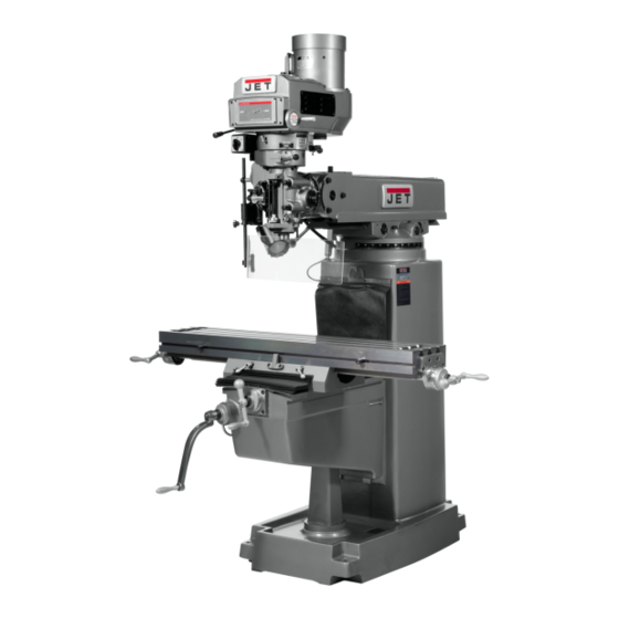
Summary of Contents for Jet JTM-1050VS2
- Page 1 This .pdf document is bookmarked Operating Instructions and Parts Manual Variable Speed Turret Mill Model JTM-1050VS2 427 New Sanford Road LaVergne, Tennessee 37086 M-691050 Ph.: 800-274-6848 Edition 2 11/2019 www.jettools.com Copyright © 2018 JET...
-
Page 2: Important Safety Instructions
If used for other purposes, coolant container protect yourself JET disclaims any real or implied warranty and accordingly. holds itself harmless from any injury that may result from that use. 20. Keep visitors a safe distance from the work area. - Page 3 28. Do not stand on the machine. Serious injury WARNING: Some dust, fumes and gases could occur if the machine tips over. created by power sanding, sawing, grinding, drilling, welding and other construction activities 29. Never leave the machine running unattended. contain chemicals known to the State of Turn the power off and do not leave the California to cause cancer and birth defects or...
-
Page 4: Table Of Contents
13.6.1 JTM-1050VS2 One-Shot Lubrication System – Exploded View ............34 13.6.2 JTM-1050VS2 One-Shot Lubrication System – Parts List ..............34 13.6.1 JTM-1050VS2 Work Lamp & Connector Box – Exploded View ............35 13.6.2 JTM-1050VS2 Work Lamp & Connector Box – Parts List ..............35 ... -
Page 5: About This Manual
Do not operate this machine until appropriate training and knowledge have been acquired. If there are questions or comments, please contact your local supplier or JET. JET can also be reached at our web site: www.jettools.com. - Page 6 2598 lbs. (1178 kg) The specifications in this manual were current at time of publication, but because of our policy of continuous improvement, JET reserves the right to change specifications at any time and without prior notice, without incurring obligations.
-
Page 7: Jtm-1050Vs2 Machine Dimensions
5.0 JTM-1050VS2 Machine dimensions Figure 5-1: machine dimensions... -
Page 8: Jtm-1050Vs2 Features
6.0 JTM-1050VS2 Features Figure 6-1: Features 5HP Motor 17. Pleated way cover Lifting ring 18. Table locking handle (x2) 19. Flat way cover Ram lock bolt (x2) 20. Column Turret scale 21. Spindle, R8 taper Ram pinion 22. Head assembly (see sect. 9.2 for explanation Machine I.D./Warning Label... -
Page 9: Set-Up And Assembly
Oil Can * Elevating Crank Handle Read and understand entire Handwheel contents of this manual before attempting set- Coarse Feed Handle up or operation. Failure to comply may cause Lifting ring serious injury. Operator’s Manual Product Registration Card 7.0 Set-up and assembly * parts with asterisk are also included in tool box service kit JTM1050VS2-TB. -
Page 10: Completing Assembly
When lifting using the ring, the machine may 7.4 Completing assembly tend to tip forward. If you wish, you can minimize this tipping by rigging a support sling over the front of the machine. Be careful when Before attempting to raise mill doing this, to prevent the sling from damaging head, familiarize yourself with instructions in any components on the front of the machine. -
Page 11: Lubrication
Do not attempt to change spindle RPM while motor is stopped. Only change spindle speeds The JTM-1050VS2 Mill is rated at 230/460V, 3- phase and comes from the factory prewired at while motor is running. 230V. Confirm power at the site matches power ... -
Page 12: Operating Controls
9.2 Operating controls Refer to Figure 9-1. A. Variable speed control (A, Figure 9-1) – Turn handwheel to adjust spindle speed. Change spindle speed only when motor is running. Failure to comply may result in damage to drive mechanism. B. Variable speed dial indicator (B) – Indicates selected speed in high or low range. -
Page 13: Control Positions For Milling And Drilling Operations
(Refer to Figure 10-3 and accompanying feed speeds (0.0015”, 0.003”, and 0.006”) text for further detail.) If control does not per spindle revolution. Allow pin to drop into engage easily, move handwheel (J) back detent. The selector engages more easily and forth to aid engagement. -
Page 14: Adjustments
10.3 Changing speed range 10.0 Adjustments To change from high to low speed range, push in lever (D, Figure 9-1) and rotate it almost 180 10.1 Drawbar operation - changing degrees. Lever will stay in position once pressure tooling is released. Apply spindle brake and loosen draw bar two Do not change gears while or three turns (counterclockwise) with the... -
Page 15: Automatic Feed
Use coarse or fine manual downfeed. Choose downfeed rate (M). Note: A test cut is recommended to verify that Engage feed reversing knob (K). See Table 4. depth of cut is correct before engaging actual Engage feed trip lever (I). workpiece. -
Page 16: Mill Head - Front/Back Tilt
Before applying final torque, check to make sure mill head is perpendicular to worktable. Set up a dial indicator in a collet and secure using draw bar (see Figure 10-5). Figure 10-6: Mill head movement – tilting Support mill head with your free hand. Press upward on spindle when tilting. -
Page 17: Feed Trip Adjustment
Figure 10-7: Ram positioning 10.8.2 Rotating ram on turret Figure 10-8: Table movement Refer to Figure 10-7. 10.10 Feed Trip Adjustment Make sure machine base is Refer to Figure 10-9. secured to floor before repositioning ram. Loosen lock nut (A, Figure 10-9). Center of gravity can shift enough to cause machine to tip over, resulting in serious injury Engage trip handle (C) by pulling it away from... -
Page 18: User-Maintenance
Always disconnect machine from power source before doing maintenance. If you do not have knowledge or training to complete the maintenance, have an authorized JET service center maintain your mill. Failure to comply may cause serious bodily injury. 11.1 General maintenance ... -
Page 19: Leadscrew Backlash Adjustment
11.3.3 Table gib Remove pleated way cover. Open chip guards (#51-53, sect. 13.3.1) Adjust gib between table and saddle by turning two enough to expose cross feed adjustment nut adjustment screws (C, Figure 11-3) at left and right (the nut toward rear of feed nut bracket is not of saddle. -
Page 20: Recommended Speed For Mill And Drill Operations
Number of your machine available when you call will allow us to serve you quickly and accurately. Non-proprietary parts, such as fasteners, can be found at local hardware stores, or may be ordered from JET. Some parts are shown for reference only, and may not be available individually. -
Page 21: Jtm-1050Vs2 Upper Head Assembly - Exploded View
13.1.1 JTM-1050VS2 Upper Head Assembly – Exploded View... -
Page 22: Jtm-1050Vs2 Upper Head Assembly - Parts List
13.1.2 JTM-1050VS2 Upper Head Assembly – Parts List Index No Part No Description Size 1 ....JTM949EVS-A77 ..Upper Guard ....................1 2 ....JTM1254RVS-A02 ..Motor Disc – Upper ..................1 3 ....TS-1523011 ....Socket Set Screw ............ M6x6L ......3 4 .... - Page 23 Index No Part No Description Size 63 ....JTM949EVS-A32 ..Timing Belt ............... 225L100 ......1 64 ....JTM949EVS-A19 ..Ball Bearing Bracket ..................1 65 ....BB-6203ZZ ....Ball Bearing ............. 6203ZZ ......2 66 ....JTM949EVS-A18 ..Gear ....................... 1 67 ....
- Page 24 134 .... JTM949EVS-A91 ..Push Plate ..................... 1 135 .... JTM949EVS-A92 ..Limit Switch ....................1 136 .... JTM1050VS2-A136 ... Motor Label ....................1 137 .... JET-165 ..... JET Logo ..............165 x 68 mm ....1...
-
Page 25: Jtm-1050Vs2 Lower Head Assembly - Exploded View
13.2.1 JTM-1050VS2 Lower Head Assembly – Exploded View... -
Page 26: Jtm-1050Vs2 Lower Head Assembly - Parts List
13.2.2 JTM-1050VS2 Lower Head Assembly – Parts List Index No Part No Description Size 1 ....TS-1503031 ....Hex Socket Cap Screw ..........M6x12L ......1 2 ....TS-1550041 ....Flat Washer ............. Ø6xØ16x2t ....1 3 ....JTM949EVS-B07 ..Worm Gear Spacer ..................1 3A .... - Page 27 Index No Part No Description Size 75 ....JTM949EVS-B75 ..Clutch Ring ....................1 76 ....5302731 ....Socket Set Screw ............ M8x6L ......2 77 ....JTM949EVS-B77 ..Handle ......................1 78 ....JTM949EVS-B78 ..Overload Clutch Lockout ................1 79 ....
- Page 28 Index No Part No Description Size 133 .... JTM949EVS-B133 ..Nose Piece ....................1 134 .... JTM949EVS-B134 ..Spindle Shield ....................1 135 .... BB-7207C ....Ball Bearing ............. 7207C ......2 136 .... JTM949EVS-B136 ..Bearing Spacer (large) .................. 1 136A ..
-
Page 29: Jtm-1050Vs2 Column And Base Assembly - Exploded View
13.3.1 JTM-1050VS2 Column and Base Assembly – Exploded View... -
Page 30: Jtm-1050Vs2 Column And Base Assembly - Parts List
13.3.2 JTM-1050VS2 Column and Base Assembly – Parts List Index No Part No Description Size 1 ....TS-2249252 ....Socket Head Button Screw .......... M10x25L ......4 2 ....JTM949EVS-C31 ..Bushing ........................ 2 3 ....JTM949EVS-C30 ..Nut ........................2 4 .... - Page 31 121 .... JTM1254VS-C91 ..Pointer ......................2 122 .... JTM949EVS-C84 ..Side Cover ..................... 1 123 .... JET-254 ..... JET Logo ..............254x105 mm ....2 124 .... LM000357 ....ID/Warning Label ................... 1 ....JTM1050VS2-TB ..Tool Box Kit Complete (not shown) ............... 1...
-
Page 32: Jtm-1050Vs2 Table Leadscrew Assembly - Exploded View
13.4.1 JTM-1050VS2 Table Leadscrew Assembly – Exploded View 13.4.2 JTM-1050VS2 Table Leadscrew Assembly – Parts List Index No Part No Description Size 1 ....TS-0561052 ....Hex Nut ..............1/2"-20UNF ....3 2 ....JTM949EVS-D02 ..Handle ..............3/8" ........ 3 3 .... -
Page 33: Jtm-1050Vs2 Spindle Guard Assembly - Exploded View
13.5.1 JTM-1050VS2 Spindle Guard Assembly – Exploded View 13.5.2 JTM-1050VS2 Spindle Guard Assembly – Parts List Index No Part No Description Size ....JTM949EVS-SGA ..Spindle Guard Assembly (#1 thru 10) ............1 1 ....TS-1502101 ....Hex Socket Cap Screw ..........M5x45L ......2 2 .... -
Page 34: Jtm-1050Vs2 One-Shot Lubrication System - Exploded View
13.6.1 JTM-1050VS2 One-Shot Lubrication System – Exploded View 13.6.2 JTM-1050VS2 One-Shot Lubrication System – Parts List Index No Part No Description Size 1 ....LT-8 ......Manual Oiler ....................1 2 ....TS-1503061 ....Hex Socket Cap Screw ..........M6x25L ......4 3 .... -
Page 35: Jtm-1050Vs2 Work Lamp & Connector Box - Exploded View
13.6.1 JTM-1050VS2 Work Lamp & Connector Box – Exploded View 13.6.2 JTM-1050VS2 Work Lamp & Connector Box – Parts List Index No Part No Description Size 1 ....JTM1050VS2-G01 ..Pan Head Screw ............M4x16L ......4 2 ....JTM1050VS2-G02 ..Plastic Connector Box Cover ................. 1 3 .... -
Page 36: Electrical Connections For Jtm-1050Vs2
14.0 Electrical connections for JTM-1050VS2... -
Page 37: Warranty And Service
JET sells through distributors only. The specifications listed in JET printed materials and on official JET website are given as general information and are not binding. JET reserves the right to effect at any time, without prior notice, those alterations to parts, fittings, and accessory equipment which they may deem necessary for any reason whatsoever. - Page 38 This page intentionally left blank.
- Page 39 This page intentionally left blank.
- Page 40 427 New Sanford Road LaVergne, Tennessee 37086 Phone: 800-274-6848 www.jettools.com...
Need help?
Do you have a question about the JTM-1050VS2 and is the answer not in the manual?
Questions and answers