Advertisement
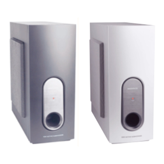
Active Subwoofer
Service
Service
Service
Service
Service
Service Manual
©
Copyright 2002 Philips Consumer Electronics B.V. Eindhoven, The Netherlands
All rights reserved. No part of this publication may be reproduced, stored in a retrieval system or
transmitted, in any form or by any means, electronic, mechanical, photocopying, or otherwise
without the prior permission of Philips.
Published by KC-ET0232 Service Audio Printed in The Netherlands
Version 1.1
TABLE OF CONTENTS
Location of PC Boards/Specifications ........................ 1-2
Specifications ..............................................................1-2
Measurement Setup ................................................... 1-3
ESD & Safety Instruction ............................................ 1-4
Disassembly Instructions & Service Positions .............. 2
Set Block & Wiring Diagram .......................................... 3
Power Board .................................................................. 4
Combi Board .................................................................. 5
Mechanical Exploded View & Parts List ........................ 6
History ............................................................................ 7
Subject to modification
SW200/
SW2000/
Page
GB
17/17S
00S/02S
3139 785 30093
Advertisement

Related Manuals for Philips SW200


Summary of Contents for Philips SW200
-
Page 1: Table Of Contents
History ................7 © Copyright 2002 Philips Consumer Electronics B.V. Eindhoven, The Netherlands All rights reserved. No part of this publication may be reproduced, stored in a retrieval system or transmitted, in any form or by any means, electronic, mechanical, photocopying, or otherwise without the prior permission of Philips. -
Page 2: Location Of Pc Boards/Specifications
Phase Switch..............................0 ,180 Input Sensitivity (Subwoofer In)........................200 mVrms AC Power (for SW200/17/17S) ......................120V / 60Hz AC Power (for SW2000/00S/02S/15S)....................220-240V / 50Hz Power Consumption......................53 W (at 1/8 Rated Power) Dimensions (w x h x d)....................135 mm x 337 mm x 375 mm... -
Page 3: Measurement Setup
MEASUREMENT SETUP... -
Page 4: Esd & Safety Instruction
ESD & SAFETY INSTRUCTION WAARSCHUWING WARNING Alle IC’s en vele andere halfgeleiders zijn All ICs and many other semi-conductors are gevoelig voor electrostatische ontladingen susceptible to electrostatic discharges (ESD). (ESD). Careless handling during repair can reduce life Onzorgvuldig behandelen tijdens reparatie kan drastically. - Page 5 DISASSEMBLY INSTRUCTIONS Dismantling the Grill Base & Speaker Driver 2. Place the Subwoofer Box as shown in the Picture 2 1. Place the Subwoofer Box as shown in the Picture 1 and loosen 4 screws A to remove the Speaker Driver. and use a screw driver to force open the Grill Base.
- Page 6 SERVICE POSITION...
-
Page 7: Set Block & Wiring Diagram
SET BLOCK DIAGRAM AMPLIFIER BOARD INPUT BOARD LED BOARD POWER BOARD... - Page 8 SET WIRING DIRGRAM INPUT PCB LVM0180C021 LVM0180C011 AMPLIFIER PCB LVM0180C031 LED PCB either fixed POWER PCB detachable...
-
Page 9: Power Board
PCB LAYOUT VIEW - POWER BOARD C358 C359 C361 C362 C363 C364 POWER BOARD C901 CN901 B2 CN902 B3 D353 D354 D355 D356 F901 Q354 Q355 Q357 TABLE OF CONTENTS Q377 R378 PCB Layout View ..............4-1 Circuit Diagram ..............4-2 R379 Electrical Parts List .............. - Page 10 CIRCUIT DIAGRAM - POWER BOARD C358 C359 C361 C362 C363 C364 C901 CN901 C5 CN902 B5 TO POWER AMP BOARD CN906 D353 D354 RB906 D354 IN4001 D355 Q357 20.1V D356 R382 2SC945 300 1/2 16.7V D355 IN4001 F901 Q354 T902 C361 Q355 C362...
- Page 11 ELECTRICAL PARTS LIST - POWER BOARD MISCELLANEOUS CN901 9965 000 12636 CONNECTOR 4 PIN P=3,96MM CN902 9965 000 12636 CONNECTOR 4 PIN P=3,96MM F901 4822 070 33152 FUSE T3,15A 250V SLOW /17/17S F901 9965 000 16184 FUSE T4A 250V SLOW /00S/02S/15S RL901 9965 000 09708 RELAY GJ-SH-112DM 320...
-
Page 12: Combi Board
INTERNAL IC DIAGRAM COMBI BOARD TABLE OF CONTENTS Internal IC Diagram............. 5-1 Circuit Diagram ..............5-2 PCB Layout View ..............5-3 Electrical Parts List .............. 5-4... - Page 13 CIRCUIT DIAGRAM - COMBI BOARD C301 JK301 D2 C302 LD401 D5 C303 Q351 C304 Q352 C305 Q353 C306 R301 C340 R302 C351 R303 C352 R304 C353 R340 C354 R350 C355 R351 C356 R352 C357 R353 C360 R354 C401 R355 C402 R356 C403 R357...
- Page 14 PCB LAYOUT VIEW - COMBI BOARD R359 C301 C918 C302 C919 R360 C303 CN301 B1 R361 C304 CN351 B8 R362 R363 C305 CN401 B8 R364 C306 CN503 B6 C340 CN906 C8 R365 C351 D351 R366 R367 C352 D352 R368 C353 D504 C354 DB901 C6...
- Page 15 ELECTRICAL PARTS LIST - COMBI BOARD (AMPLIFIER, INPUT, LED & EARPHONE PARTS) ELECTRICAL PARTS LIST - COMBI BOARD (AMPLIFIER, INPUT, LED & EARPHONE PARTS) MISCELLANEOUS CN906 9965 000 12617 CONNECTOR 3PIN PITCH=3,96MM C908 2038 554 00065 100NF +80/-20% 50V R514 4822 050 24703 47K 1% 0,6W C913...
- Page 16 MECHANICAL EXPLODED VIEW For SW2000/00S & /02S...
- Page 17 MECHANICAL & ACCESSORIES PARTS LIST - MAIN UINT SCREW LIST - MAIN UINT 9965 000 15982 FRONT PANEL ASSY /00S/02S/15S D3 x 10 9965 000 14650 FRONT PANEL ASSY D3 x 6 9965 000 14648 FRONT PANEL ASSY /17S M4 x 25 9965 000 14651 CLOTH FRAME ASSY /00S/02S/17...
-
Page 18: History
Version 1.0 Initial release Version 1.1 New type/version SW2000/00S/02S has been added Correction of Service Manual pages Page 1-2 : Correction Type version in the Specification SW200/17/17S (was SW3500/37S) Page 6-2 : Correction of part code for pos A1 and A2.
Need help?
Do you have a question about the SW200 and is the answer not in the manual?
Questions and answers