Advertisement
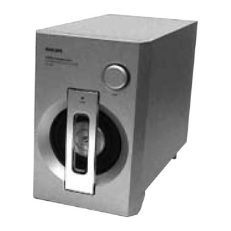
Powered Subwoofer
Service
Service
Service
Service
Service
Service Manual
©
Copyright 2002 Philips Consumer Electronics B.V. Eindhoven, The Netherlands
All rights reserved. No part of this publication may be reproduced, stored in a retrieval system or
transmitted, in any form or by any means, electronic, mechanical, photocopying, or otherwise
without the prior permission of Philips.
Published by BB 0205 Service Audio
Version 1.0
Technical Specifications
Mains Voltage
Mains Frequency
Output Power (55Hz, 10% THD)
Input Sensitivity (55Hz, 100W)
S/N Ratio (100Hz, 200mV)
Minimum Volume Hum & Noise
Frequency Response (-3dB)
Distortion (100Hz, 200mV)
* at Output level of 2V across 4 ohm load
Printed in The Netherlands
Subject to modification
: 230V
: 50Hz
: 100W at 4 ohm load
: < 220mV
: > 60dB*
: < 3mV
Low
: <40Hz
High
: 110Hz - 140Hz
: < 1%*
SW988/
00S
(3139 118 79380)
GB
3139 785 30048
Advertisement
Table of Contents

Related Manuals for Philips SW988/00S


Summary of Contents for Philips SW988/00S
- Page 1 * at Output level of 2V across 4 ohm load © Copyright 2002 Philips Consumer Electronics B.V. Eindhoven, The Netherlands All rights reserved. No part of this publication may be reproduced, stored in a retrieval system or transmitted, in any form or by any means, electronic, mechanical, photocopying, or otherwise without the prior permission of Philips.
-
Page 2: Dismantling Instructions
DISMANTLING INSTRUCTIONS Dismantling the Grille Base & Speaker Driver 1. Place the Subwoofer Box upside down and remove the 2. Unscrew 4 screws C (see Picture 3) to remove the 4 Rubber Foot A (see Picture 1). Then unscrew 4 screws Speaker Driver (pos. - Page 3 DISMANTLING INSTRUCTIONS Dismantling the Rear Assembly 1. Unscrew 10 screws E (see Picture 7) to pull out the pc board assembly. Caution: Do not break the bundle of wires to the front. Picture 7 Service Position...
-
Page 4: Wiring Diagram
WIRING DIAGRAM... -
Page 5: Component Layout
COMPONENT LAYOUT... -
Page 6: Electrical Parts List
ELECTRICAL PARTS LIST MISCELLANEOUS F901 4822 070 35002 Fuse T5A 250V C908 2038 554 00065 100nF +80/-20% 50V F902 4822 070 35002 Fuse T5A 250V C911 2038 554 00065 100nF +80/-20% 50V JK301 4822 267 41238 RCA Jack 1P C912 2038 554 00065 100nF +80/-20% 50V L501... -
Page 7: Circuit Diagram
CIRCUIT DIAGRAM : Provision. Note : All capacitors are in uF unless otherwise specified. All resistors are 1/6W 5% unless otherwise specified. Some values may varies, see respective parts list for correct value. ELECTRICAL PARTS LIST ELECTRICAL PARTS LIST RESISTORS R529 4822 050 24703 47k 1% 0,6W... -
Page 8: Exploded View
EXPLODED VIEW MECHANICAL PARTS LIST 9965 000 12141 Volume Knob 9965 000 12142 Bar Trim (Lens) 9965 000 12149 Front Cabinet 9965 000 12144 Woox Speaker 9965 000 09700 Foot 9965 000 09701 Foot D30X35mm 9965 000 09702 Rubber Pad 4822 532 13065 Speaker Sponge 9965 000 08277...
Need help?
Do you have a question about the SW988/00S and is the answer not in the manual?
Questions and answers