Advertisement
Quick Links
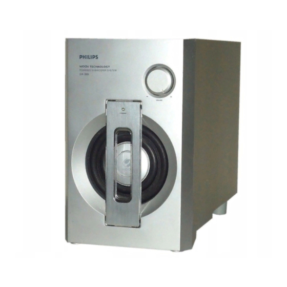
Active Subwoofer
Service
Service
Service
Service
Service
Service Manual
©
Copyright 2002 Philips Consumer Electronics B.V. Eindhoven, The Netherlands
All rights reserved. No part of this publication may be reproduced, stored in a retrieval system or
transmitted, in any form or by any means, electronic, mechanical, photocopying, or otherwise
without the prior permission of Philips.
Published by KC-ET0227 Service Audio Printed in The Netherlands
Version 1.0
TABLE OF CONTENTS
SW3700 Location of PC Boards/Specifications ......... 1-2
SW3800 Location of PC Boards/Specifications ......... 1-3
Measurement Setup ................................................... 1-4
ESD & Safety Instruction ............................................ 1-5
Disassembly Instructions & Service Positions .............. 2
Set Block & Wiring Diagram .......................................... 3
Amplifier / Jack / LED Board .......................................... 4
Power & VR Board ........................................................ 5
Mechanical Exploded View & Parts List ........................ 6
Subject to modification
SW3700/
SW3800/
Page
GB
17S
00S
3139 785 30068
Advertisement

Related Manuals for Philips SW3700/17S


Summary of Contents for Philips SW3700/17S
- Page 1 Mechanical Exploded View & Parts List ......6 © Copyright 2002 Philips Consumer Electronics B.V. Eindhoven, The Netherlands All rights reserved. No part of this publication may be reproduced, stored in a retrieval system or transmitted, in any form or by any means, electronic, mechanical, photocopying, or otherwise without the prior permission of Philips.
- Page 2 LOCATION OF SW3700 PC BOARDS AMPLIFIER PCB JACK PCB LED PCB POWER PCB VR PCB SPECIFICATIONS SUBWOOFER Subwoofer (not magnetically shielded design).......................6.5" Output Power............................50W (4Ω,DIN) THD (Total Harmonic Distortion) ......................10% at 55 Hz Reproduction Frequency Response.......................40 Hz-150 Hz Phase Switch..............................0 ,180 Input Sensitivity (Subwoofer In).........................500 mVrms AC Power ...............................120V / 60 Hz...
-
Page 3: Specifications
LOCATION OF SW3800 PC BOARDS AMPLIFIER PCB JACK PCB LED PCB POWER PCB SPECIFICATIONS SUBWOOFER Subwoofer (not magnetically shielded design).......................6.5" Output Power............................1000W (4Ω,DIN) THD (Total Harmonic Distortion) ......................10% at 55 Hz Reproduction Frequency Response.......................30 Hz-140 Hz Phase Switch..............................0 ,180 Input Sensitivity (Subwoofer In).........................200 mVrms AC Power ............................220 - 240V / 50 Hz power Consumption......................66 W (at 1/8 Rated Power) Dimensions (w x h x d)....................200 mm x 310mm x 350 mm... -
Page 4: Measurement Setup
MEASUREMENT SETUP... -
Page 5: Esd & Safety Instruction
ESD & SAFETY INSTRUCTION WAARSCHUWING WARNING Alle IC’s en vele andere halfgeleiders zijn All ICs and many other semi-conductors are gevoelig voor electrostatische ontladingen susceptible to electrostatic discharges (ESD). (ESD). Careless handling during repair can reduce life Onzorgvuldig behandelen tijdens reparatie kan drastically. - Page 6 DISASSEMBLY INSTRUCTIONS Dismantling the Front Assembly Dismantling the Grill Base & Speaker Driver 1. Place the Subwoofer Box as shown in the Picture 3 (Bottom view) and use a screw driver to force open the front assembly. 1. Place the Subwoofer Box as shown in the Picture 1 Caution: Do not break the bundle of wires to the front.
- Page 7 SERVICE POSITION FOR SW3700 SERVICE POSITION FOR SW3800...
- Page 8 BLOCK DIAGRAM...
- Page 9 WIRING DIAGRAM...
- Page 10 TDA7293 INTERNAL DIAGRAM BUFFER DRIVER +PWVs AMPLIFIER / JACK / LED BOARD BOOT LOADER SGND BOOTSTRAP CLIP DET MUTE THERMAL MUTE SHUTDOWN PROTECTION STBY STBY STBY-GND -PWVs TABLE OF CONTENTS Internal IC Diagram & Voltages..........4-1 VOLTAGES Circuit Diagram ..............4-2 PCB Layout View ..............
- Page 11 CIRCUIT DIAGRAM C301 D1 C401 A1 C413 B4 R382 C3 R512 A4 R522 A6 RB401 C2 C356 B2 C506 C515 A6 C914 D302 IC401-B A1 Q305 R352 B1 R362 B2 R372 C3 R411 C4 C302 C1 C358 D3 C402 A1 C414 B4 C507 C517 B3...
- Page 12 PCB LAYOUT VIEW C301 C4 CN401 R373 C302 B4 CN501 R374 C303 A1 CN511 R375 C304 A1 CN905 R376 C305 B1 D301 R377 C306 B1 D302 R378 C351 B1 D303 R379 C352 B1 D304 R380 C353 B1 D305 R381 C354 B1 D306 R382 C355 C1...
- Page 13 ELECTRICAL PARTS LIST - AMPLIFIER, JACK AND LED BOARD ELECTRICAL PARTS LIST - AMPLIFIER, JACK AND LED BOARD MISCELLANEOUS C509 4822 122 33293 100pF 5% 50V R376 4822 050 21003 10K 1% 0,6W D305 4822 130 30621 1N4148 F902 4822 070 34002 FUSE T4A 250V SLOW /00S C510...
- Page 14 POWER & VR BOARD TABLE OF CONTENTS Power PCB schematic and Layout View ........5-2 VR PCB schematic and Layout View ..........5-3 Electrical Parts List ................. 5-4...
-
Page 15: Power Schematic Diagram
POWER SCHEMATIC DIAGRAM C901 CN901 B2 D901 D902 D903 F901 RB902 A2 RB905 B1 RL901 T902 POWER PCB LAYOUT VIEW C901 CN901 A1 D901 D902 D903 F901 RB902 B1 RB905 B1 RL901 T902... - Page 16 VR SCHEMATIC DIAGRAM RB401 A1 VR401 A1 VR PCB LAYOUT VIEW RB401 A2 VR401 A1...
- Page 17 ELECTRICAL PARTS LIST - POWER & VR BOARD MISCELLANEOUS CN901 9965 000 12636 CONNECTOR 4 PIN P=3,96MM F901 9965 000 12638 FUSE T2A 250V SLOW /00S F901 9965 000 14309 FUSE T2A 250V SLOW /17S RB902 9965 000 12636 CONNECTOR 4 PIN P=3,96MM RL901 9965 000 09708 RELAY GJ-SH-112DM 320R T902...
- Page 18 SW3700 Exploded Drawing...
- Page 19 SW3800 Exploded Drawing...
- Page 20 FOR SW3700/17S ONLY FOR SW3800/00S ONLY MECHANICAL PARTS LIST MECHANICAL PARTS LIST 9965 000 14284 VOLUME KNOB 9965 000 12141 VOLUME KNOB 9965 000 14285 FRONT CAB 9965 000 12142 BAR TRIM (LENS) 9965 000 03360 FOOT 9965 000 14312...
Need help?
Do you have a question about the SW3700/17S and is the answer not in the manual?
Questions and answers